The Mighty Manfred/Manfrotto tripod
 A sturdy and
versatile tripod is one of the best tools a photographer can have. But
good tripods are expensive! After years of making do with a cheap video
tripod that almost wobbled more than when hand-shooting, I finally decided
to build my own quality tripod - in good old style, from wood! I bought
a ready-made ball head, a Manfrotto (Bogen in the USA) model
#352, and crafted everything else from wood, brass, PVC, aluminum and nylon.
That's why I called it the Manfred/Manfrotto tripod - the body built by
me, the head by Manfrotto.
A sturdy and
versatile tripod is one of the best tools a photographer can have. But
good tripods are expensive! After years of making do with a cheap video
tripod that almost wobbled more than when hand-shooting, I finally decided
to build my own quality tripod - in good old style, from wood! I bought
a ready-made ball head, a Manfrotto (Bogen in the USA) model
#352, and crafted everything else from wood, brass, PVC, aluminum and nylon.
That's why I called it the Manfred/Manfrotto tripod - the body built by
me, the head by Manfrotto.
This tripod was designed to be able to support any of my cameras and
lenses with enough stiffness to use any exposure time; to be tall enough
to place the camera at eye level; to be versatile enough to reach ground
level and any strange location; and to be light enough to be carried a
reasonable distance, but without expecting to take it on a long mountaineering
trip. It also had to be water-resistant, to set it up in a river.
The legs have only two sections each. They fold over rather than telescoping,
making the collapsed tripod about as small as a three-section telescoping
design of the same tallness. All joints are compressed during use, eliminating
any possibility of play.
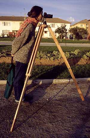
I forced my sister to volunteer as a model for making this small series
of photos, during sunset, in the park around my home. Since she is a little
smaller than I am, this photo shows the tripod set up with widely spread
legs. When I use it, I close the legs a little more, placing the camera
5cm higher.
 For photographing
lower objects, it's best to use the tripod with folded lower legs. The
knee junctions are rounded, just like the main feet, so they can perfectly
well serve as alternate feet. In this configuration, the camera ends up
slightly higher than typical table height, which tends to be ideal to shoot
macros of small technical objects placed on a desk.
For photographing
lower objects, it's best to use the tripod with folded lower legs. The
knee junctions are rounded, just like the main feet, so they can perfectly
well serve as alternate feet. In this configuration, the camera ends up
slightly higher than typical table height, which tends to be ideal to shoot
macros of small technical objects placed on a desk.
This configuration provides extreme stability. The tripod can hold a
heavy 1000mm mirror lens without noticeable shake, even in strong wind.
Regardless of whether the main feet or the knees are used, this tripod
always stands on wood. Commercial tripods tend to have a choice between
rubber feet or metal spikes. I never liked that! The rubber feet make a
tripod wobble, while spikes tend to slowly bury themselves in soft ground;
both things are bad for stability! In addition, the spikes can scratch
a floor. Rounded wooden feet instead provide an ample contact surface without
excessive elasticity. On smooth floors they tend to slip, but with the
stiffness of this tripod, and the combined weight of it with the camera,
this has proven to be no problem.
Up to here this tripod looks pretty normal. But now the fun starts!
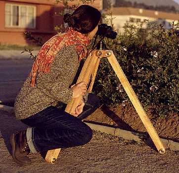
 When you want to
get close to some object, the ability to tilt the tripod forward is a great
asset. The complete movability of all joints of my tripod can achieve this
far better than most factory-made ones. Here it is holding a typical 35mm
reflex camera with an average-sized lens. The tripod's extended leg is
heavy enough to safely hold the camera in this configuration. If more tilt
is required, something can be used to weigh down the extended leg.
When you want to
get close to some object, the ability to tilt the tripod forward is a great
asset. The complete movability of all joints of my tripod can achieve this
far better than most factory-made ones. Here it is holding a typical 35mm
reflex camera with an average-sized lens. The tripod's extended leg is
heavy enough to safely hold the camera in this configuration. If more tilt
is required, something can be used to weigh down the extended leg.
The ball head is extremely convenient. It allows to grasp the set screw
with the left hand, the camera with the right, then aim the camera in any
desired way and lock the single set screw with a short motion. It is very
quick to set up. The Manfrotto #352 is not very large, but still stiff
enough to hold any of my photo equipment. For large cameras a larger ball
mount could be used, but I would not use any other kind of mount, which
would require loosening and setting several screws each time the camera
is moved!
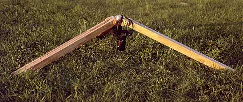 Upside down!
For objects at ground level, this configuration is great. The legs can
be adjusted to any required angle, extended, or folded like here, placing
the camera at any required height from zero to about 160 cm.
Upside down!
For objects at ground level, this configuration is great. The legs can
be adjusted to any required angle, extended, or folded like here, placing
the camera at any required height from zero to about 160 cm.
This picture gives a view of the aluminum back plate opposing the Manfrotto
ball head on the other side of the tripod's triangle. This piece is nothing
more than a very big and fancy washer! The ball head is mounted to the
triangle using a 3/8 inch Allen bolt. The washer was turned to properly
fit the bolt head, and apply pressure to the wood on the periphery only.
This aids stability.
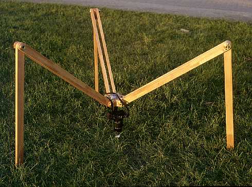 This is the spider
setup. It is less stiff than the one before, but would be the configuration
of choice when setting up in mud - it's easier to clean the straight feet
than the knee joints!
This is the spider
setup. It is less stiff than the one before, but would be the configuration
of choice when setting up in mud - it's easier to clean the straight feet
than the knee joints!
All wooden parts were thoroughly impregnated in polyurethane varnish
of the same kind used to seal wooden floors. It makes the wood completely
water resistant, and provides very hard surfaces which are next to impossible
to scratch. The finishing operation involves sanding the wood smooth, breaking
the edges, then soaking it in diluted varnish. Once it has dried, the pieces
are again lightly sanded using fine sandpaper (#180 or so) to remove the
little fibers that have stood up. The holes are treated with the drill
bit, for the same purpose. Then two more layers of varnish are brushed
on.
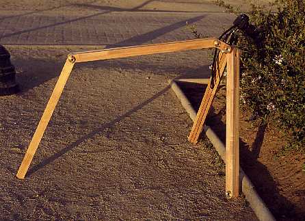
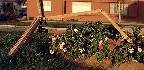 Now things start
getting fancy! This setup has proven to be very useful for photographing
all kinds of objects near ground level which need more distance than what
one could get in a more normal configuration. Of course, one must be careful
to get the tripod leg out of the picture!
Now things start
getting fancy! This setup has proven to be very useful for photographing
all kinds of objects near ground level which need more distance than what
one could get in a more normal configuration. Of course, one must be careful
to get the tripod leg out of the picture!
Sorry about the tree in the background, which seems to be growing out
of the tripod. That's a very common beginner's mistake! Even being seasoned
by 24 years of hobby photography doesn't always prevent this, when shooting
a few photos for a web page, in a hurry, just before the sun sets
for good!
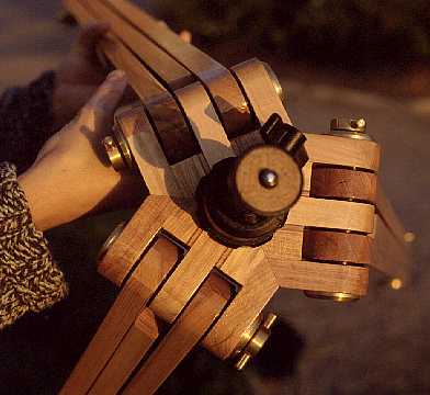
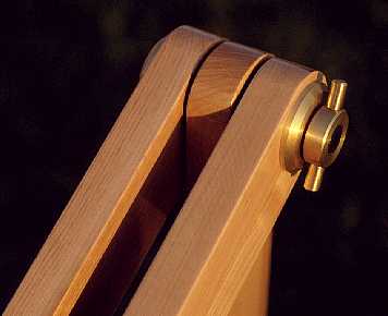 This closeup gives
an idea of the effort invested in my tripod. I tried to make it not just
useful, but also beautiful!
This closeup gives
an idea of the effort invested in my tripod. I tried to make it not just
useful, but also beautiful!
The wood I used is Lenga. This is a hardwood that's quite abundant in
the native forest of southern Chile. I can buy it in 18x45mm size, so I
designed the tripod around this standard size. Lenga wood is of high strength,
medium weight, and looks nice.
To make the rounded ends I used a very simple method: I first drilled
the holes, then clamped a wooden block to my belt sander, drilling this
block at the proper height, equal to the radius of the rounded ends (22.5mm).
I used a drill bit as axle, plugging in each of my wooden ends, and using
a coarse sanding belt (#40 grain) I sanded them round while rotating the
pieces around their axles. It's surprisingly fast to do - just a few seconds
for each piece!
Each junction uses several brass parts: A 10mm axle, drilled and tapped
on both ends; two (different) end cups; and a wing nut, assembled from
three individual pieces. The wooden parts are separated by black PVC clutch
disks, and a low friction nylon washer goes between the wing nut and its
end cup. All these pieces were custom made on my hobby lathe. In addition,
each joint uses two M6 Allen bolts with countersunk heads, which I did
buy, instead of making them too...
 Here's a nice view
of the tripod's triangle (that's how the head piece is called), which is
assembled from no less than 21 individual pieces of wood! Building this
piece was a challenge, but unexpectedly I succeeded on the first try! I
first drilled the holes into the over-length pieces, rounded the ends,
and then assembled each sandwich of 7 pieces (5 Lenga ones, and 2 plywood
pieces) while having a drill bit inserted as an aligning axle. The assembly
is done using just carpenter's white glue, and the stack is compressed
with a clamp while the glue sets.
Here's a nice view
of the tripod's triangle (that's how the head piece is called), which is
assembled from no less than 21 individual pieces of wood! Building this
piece was a challenge, but unexpectedly I succeeded on the first try! I
first drilled the holes into the over-length pieces, rounded the ends,
and then assembled each sandwich of 7 pieces (5 Lenga ones, and 2 plywood
pieces) while having a drill bit inserted as an aligning axle. The assembly
is done using just carpenter's white glue, and the stack is compressed
with a clamp while the glue sets.
When the three stacks are ready, the difficult part comes: Sanding them
down to precise, well-fitting 120-degree angles! I achieved this by making
a sanding guide from a 45mm wide wooden piece, enhanced by two layers of
paper, clamped between two 5x5cm ones, and clamping the whole guide to
the belt sander. I could then slightly loosen the clamps and trim the angle
of the guide, until achieving the required 30 degrees up of the sander's
surface. Then I sanded down all the pieces, using the #40 sanding belt,
which took about an hour, because of the larger surfaces that had to be
sanded. Even coarser belts than #40 would be good here, but I did not find
any.
Then the triangle was assembled, again using white glue and clamping
it until the glue was dry. Lastly, the surfaces were sanded flat on the
belt sander, to even out the unavoidable little imprecisions. The last
step is drilling the centered hole for the 3/8 inch bolt that will hold
the ball head.
Note that this ball head offers both a 1/4 inch and a 3/8 inch stud.
The 1/4 inch one is fixed, while the 3/8 inch one comes in the form of
a spring-loaded sleeve enclosing the 1/4 inch stud. It's a little out of
focus here, but can be seen. This system allows to directly mount any of
my cameras or large lenses, without needing adapters. This was yet another
reason to use this head!
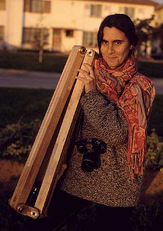 This is how the
tripod is folded for storage. The ball head ends up between the legs, saving
some packing length. Thanks to this, the entire tripod is just 88cm long
when collapsed. Certainly, it's no midget, but it's in the ballpark of
commercial tripods of the same sturdiness and maximum height, while being
more versatile!
This is how the
tripod is folded for storage. The ball head ends up between the legs, saving
some packing length. Thanks to this, the entire tripod is just 88cm long
when collapsed. Certainly, it's no midget, but it's in the ballpark of
commercial tripods of the same sturdiness and maximum height, while being
more versatile!
Never mind my sister's sour face. During set up of the tripod for all
these photos, I managed to bump my camera into her forehead three times
- and always at the same spot! It was almost as if it had been programmed!
I swear, it wasn't on purpose, but she may not have believed me!
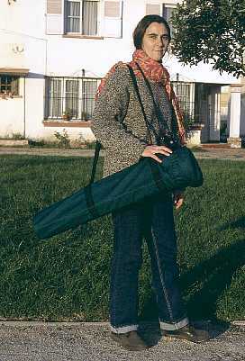 My sister with her
swollen forehead poses with the packaged tripod. This photo was shot in
the setting sun, just like the others, but I had to color-correct the scan.
Otherwise, the dark green carrying bag looked black!
My sister with her
swollen forehead poses with the packaged tripod. This photo was shot in
the setting sun, just like the others, but I had to color-correct the scan.
Otherwise, the dark green carrying bag looked black!
I made the bag too. Anyway two years ago I had to buy a heavy duty sewing
machine because of my flying hobby, for which I need to sew parachute bridles
every now and then. So it's no big task to make a bag like this. It's made
from dark green canvas, with nylon webbing reinforcements, and a shoulder
strap of that same webbing. The front side has an elastic-loaded cover
that can be easily popped off and on. It is sewn to the bag, so it can't
get lost.
The complete tripod, with its bag, weighs 5.6kg. This compares quite
well to commercially available tripods of similar sturdiness.
 If
you want to make a copy of my tripod, you are of course welcome. Here is
a drawing of the most complex part, the joint of the triangle with a leg.
The drawing is to exact scale, with two dimensions given (in millimeter)
so that you can plot it and get the other dimensions from the drawing.
Clicking on the picture will load a higher resolution version, which you
can download for printing.
If
you want to make a copy of my tripod, you are of course welcome. Here is
a drawing of the most complex part, the joint of the triangle with a leg.
The drawing is to exact scale, with two dimensions given (in millimeter)
so that you can plot it and get the other dimensions from the drawing.
Clicking on the picture will load a higher resolution version, which you
can download for printing.
The materials are color-coded: Wood is brownish, brass is red, PVC is
green, nylon is yellow, steel bolts are blue.
The shape of the brass end cups and the PVC clutch disks is such that
the compression force generated by tightening the wing nut is applied only
to the the area of greatest possible radius, maximizing the torque. At
first I made the clutch disks from nylon, but this material is so slippery
that it didn't allow to block the joints! So I had to remake all the disks,
using a different material. A fibrous plastic such as durocotton may have
been best, but not having any in my limited material stock, I settled for
black PVC, which works quite well. It slips easily when there is no compression,
and locks in well enough when the wing screw is tightened.
I made good use of the nylon's self-lubricating characteristics by making
small nylon washers that go between the wing bolt and its pressure plate.
If this washer is made larger, it will have a longer lifetime, while asking
for a little more force to block each junction.
Note that the triangle/leg junctions need to flex the wood a little
bit in order to lock or release the joint. I had my reservations with this
approach, but it turned out to work well. It requires, however, a precise
fit of the pieces. Since the wood is not very precisely sized at the lumber
yard, and I cannot do it better myself, I used the wood as it came, and
made each clutch disk to the exact size required by the tolerances of the
wood. So, the disks vary in thickness by up to 0.2mm, and are not freely
interchangeable, should I ever disassemble the tripod.
The knee joints don't have this quirk, of course, and can use any leftover
random-size clutch disks. By the way, the design of the knee joint parts
is basically the same, only that the axle is 40mm shorter.
Note the different shape of the clutch disks partially visible in the
upper corners of the drawing. It takes a little less effort to make, but
it didn't work very well, so I ended up making all disks with the shape
shown for the four lower ones.
The left Allen bolt is firmly and permanently fastened, using Loctite
high strength thread locker between all matching surfaces. So the axle
and the left end cup become effectively a single part. They could be turned
from a solid rod of brass, but this would waste a lot of material... Likewise,
the right bolt is permanently fastened in the wing nut body, again using
high strength Loctite. Its tip is lubricated with a good grease, in order
to move with little effort and wear in the brass axle. For longer lifetime,
the axle could be made from phosphor bronze instead of brass, but I don't
think this is necessary for my rather low use of this tripod.
The wings of the wing nut, which are simply small brass cylinders, were
installed in the holes of the wing nut body by a fancy and elegant method,
which looks nothing short of magic to people who watch one doing it: The
little cylinders are turned on the lathe to a diameter a few microns larger
than that of the holes. Then, the body is heated in a flame, while the
cylinders are cooled with cooling spray. The expansion of the body and
the contraction of the cylinders allow them to fit easily. One grasps them
with tweezers, assembles them quickly, and after waiting for a few seconds
for the temperatures to equalize, the two parts become as firmly locked
as if they were a single piece!
Of course, if you are less proficient with the lathe, you can make the
cylinders slightly undersize, and glue them in with Loctite. They could
also be soldered. I would not recommend to thread them and screw them in,
because this would weaken them at the most stressed location.
The drawing shows the triangle composed of 18mm Lenga pieces and 2mm
plywood fillers. But I did not find 2mm plywood, so I used 4mm one, using
half the amount of fillers. The photo of the triangle makes this clear.
It's not important and should be obvious, but I mention it just to prevent
readers from wondering about the difference between the drawing and reality.
With this information, people who have access to a lathe and a few simpler
tools should be able to duplicate my design. Those without a lathe may
still build an approximate copy, using long bolts and large washers instead
of my custom-made parts. This should be workable, but won't look as nice,
and will require more force to lock the junctions in place, since the compression
will be applied at a smaller radius and so the torque will be lower.
And even if you should never copy my design, you may at least have learned
an idea or two about tripods!
Back to homo ludens photographicus.