The Ugly Bird
Learning dronology and building a quadcopter
 After
many years of complete absence from the model aircraft hobby, in early
2020 I attended an air show given by the Chilean model aircraft
federation, and this piqued my interest in getting back into this
hobby, in one way or another. But in this stage of life I'm too lazy to
drive far away to an airfield to fly a model airplane, and on my
property, despite its generous size, I cannot start and land an
airplane, because it's densely wooded. So I decided to get back
into model aircraft by building a quadcopter.
After
many years of complete absence from the model aircraft hobby, in early
2020 I attended an air show given by the Chilean model aircraft
federation, and this piqued my interest in getting back into this
hobby, in one way or another. But in this stage of life I'm too lazy to
drive far away to an airfield to fly a model airplane, and on my
property, despite its generous size, I cannot start and land an
airplane, because it's densely wooded. So I decided to get back
into model aircraft by building a quadcopter.
Over the course of a few weeks of reading up and thinking, the
idea
matured. It would have to be a low cost quadcopter, because if anything
bad happens and the thing goes out of control, it will almost certainly
be lost, given my wild terrain. I don't want to fly anything that
would hurt my pocket too badly if lost.
The goals of building my quadcopter would be basically four:
- Do some non-professional aerial photography and filming;
- Install lines in trees, to hoist antennas;
- Learn about drone technology;
- Have fun.
While reading up about drones in general and quadcopters in particular,
I found that there is a huge fashion movement going on towards very
small and simple "racing" drones. Much of the current drone parts market in 2020
is devoted to these flea-size quads, but they are not suitable for my
purposes, because their ability to carry a stabilized camera is very
limited, and they definitely cannot carry a long line into a tall tree.
So I decided to follow a suggestion given to me during that airshow,
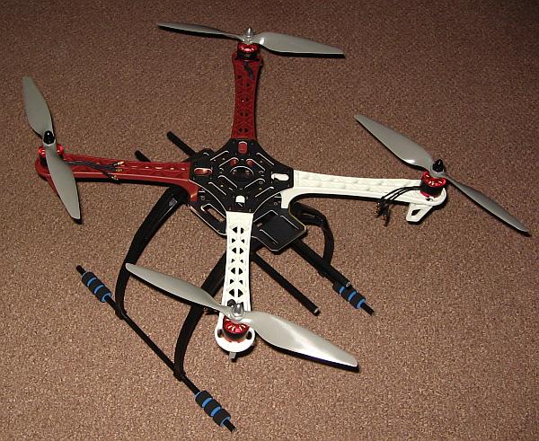
and build a drone in the line of what was a de-facto standard a
few years ago: A drone having a diagonal motor separation (called
"wheelbase" in drone jargon) of around 40 to 50cm and weighing about
1kg.
It's very easy to make the "best drone in the world", by reading
reviews and comparisons online and buying the items that get
the
top reviews. But these are also usually the most expensive items available, and one
could easily end up spending several thousand dollars on the parts for
a quadcopter! It might be really good, but far too expensive. So I
decided to see what I could achieve by using parts that have the best
performance to price ratio, rather than the best absolute performance at unlimited price.
Getting the parts
Living in Chile, with ever more limited local availability of
technical and hobby stuff, I went straight to the usual online sites
where one can shop in China. Almost everything related to drones is
made in China anyway, so it makes no sense to shop in other
countries, where mainly the same Chinese parts are sold at higher
prices.
I didn't find a really attractive, ready-made frame. The choice was
basically between various clones of the DJI F450 frame, which are cheap
but rather heavy and not very stiff, or some very expensive carbon
fiber frames, which are cobbled together from carbon fiber pipes,
flat sheets, and plastic blocks, and thus fail to make good use of the true
advantage of carbon fiber, which is the ability to make the whole frame
from one piece, with complex, flowing shapes that allow maximum
stiffness at very low weight. So I reluctantly bought an F450
clone frame, complete with landing gear, to build my first quad on it,
and later switch to something better, possibly homemade. This frame cost
just $17.39, landing gear and shipping included.
The situation with motors is much better. There are several choices of
good motors, at reasonable prices. Comparing specs and looks, and
reading all reviews I could find, I opted for a set of four Readytosky
2212 motors, having a velocity constant of 920. These cost
$23.85
total, including shipping.
The propellers are a bit of a problem. There are several kinds
available, with conflicting information about their performance. I
needed the 1045 size (10" diameter, 4.5" pitch). I ended up buying two
different types: 3 sets of Gemfan glass-filled nylon props (according to
the seller) for $13.11 total, and a single set of HJ carbon
fiber
props, for $12.55. The idea was to use the nylon props for learning,
and test whether the carbon fiber props really work so much better as to
make good for their higher price.
ESCs (electronic speed controllers) are available in many brands,
ratings, qualities, with various
capabilities, and run various firmwares. After doing my homework, I decided to buy Favourite
LittleBee Spring 2-6S 30A ones, which are small, lightweight,
efficient, have BLHeli_S firmware and support the DShot protocol. These
have a lot of headroom in my application. I also considered the smaller
20A version, to save some weight, but not knowing how much peak current
my motors would draw, I finally opted for the 30A ones. I also thought
that the few additional grams of weight could be offset by the lower
conduction losses in the bigger ESCs. They set me back $24.47 total,
including shipping.
Now it starts getting interesting. The flight controller, and the
software running on it, plays a huge role in defining the capabilities
and performance of a quadcopter. I had to read and learn a lot before
deciding, and it wasn't an easy decision. But I finally decided to use
a Pixhawk clone, and run Arducopter software on it. This seemed to be
the combination best suited to my task and intentions.
I learned that the original Pixhawk was made by a company called 3D
Robotics, the last version being 2.4.6, then they discontinued it and
moved to a new series of Pixhawk, which is much more expensive, while several companies in China make
clones of the Pixhawk 2.4.6, calling them version 2.4.8. These
are
not all equal! Some use better sensors than others, and it seems that
some use the complex supply power selection and switching of
the original Pixhawk, while others simply combine the various power
sources through diodes. It's quite involved to sort out all the many
options, most of which are poorly described on the sale pages, and this is made worse by the fact that Pixhawk clones are
often sold in kits, including various essential and non-essential
peripherals. It takes some time to sort through all this.
I finally bought a kit containing a clone Pixhawk 2.4.8, anti-vibration
mount, APM power module, SD card, pushbutton, buzzer,
uBlox M8N GPS/magnetometer module, GPS mount, PPM encoder,
USB
extension with RGB LED, and I2C splitter, with each module housed in a
plastic box. I made sure that my Pixhawk had an MS5611 barometer instead
of the less accurate MS5607 used in some other clones. The whole
Pixhawk kit cost $61, including shipping.
Larger Pixhawk kits would include telemetry radios, which link the
drone to a computer running groundstation software, but I
opted
out of this because I didn't want to drive up the complexity of my
quadcopter to that level. Every radio link one adds increases weight,
power consumption, and above all the likelihood of interference! For
those who want telemetry radios, they are available for various
frequency bands, and with various power levels, resulting in vastly different ranges.
The kit I ordered includes some modules I don't need. Most kits include
them, and kits that leave them out aren't much cheaper. So I didn't
worry about getting these useless parts, and the plus is that they come
with various additional interconnection cables, which can be repurposed
for other uses when adding payloads to the drone. The surplus modules
in my kit are the PPM encoder, which is only useful when using
an antique radio control receiver that only has independent channel
outputs; Also the I2C splitter, which is only needed
when adding
additional I2C sensors; Then the external LED and USB extension. which
I didn't use because I mounted the Pixhawk in such a position that its
built-in USB connector remains accessible; and a second buzzer. One is
enough, I would say, but the kit comes with two buzzers, a large and a
small one.
The Pixhawk kit came with a fake SD card!
It is labelled "16GB", and its controller indeed identifies
as a 16GB card, but the actual amount of memory it has is 256MB, of
which 232.8MB actually can be used for files. I discovered this when
the Pixhawk's log files started to come out blank. This fake SD card
writes the first 232.8MB just fine, and whatever follows is written
into thin air, not into memory, going straight to data nirvana. So it's
best to destroy it and throw it away, to prevent loss of log data, and
put a decent SD card into the Pixhawk.
Every web page I saw about the Pixhawk says that the pushbutton is an
essential part of the system, so I did install it on my drone. Later I
learned that it's not essential, and is actually quite unnecessary! I
configured the software so that I don't need the pushbutton, and I will
leave it out of my next build, to save some weight.
The next big decision is the radio control set. I still had
my
old Futaba Conquest "digital proportional" 4-channel radio from the
early 1990s, running on the 72MHz band, but radio control technology
has advanced so much over these many years that I decided to buy a new
set. Doing my homework I found that the Taranis models from the brand
FrSky are highly recommended, but relatively expensive, while some
other radios from the competing brand FlySky are considered to be the
best value for money. The price difference is really big, and by
comparing specs I didn't see a significant advantage for the more
expensive radios, in my application. So it was clear that I needed a
FlySky radio. The web pages most warmly
recommended the i6X
model, but the reasons were things like backward compatibility with
existing older receivers, and the presence of trim levers, which are
not needed for quadcopter flying. Since I didn't have any such older
FlySky
receivers, I opted for the i6S transmitter, which is newer and has a
totally different look, a very smooth, aesthetically pleasing one. I
have to confess that the aesthetics of this transmitter played a role
in my buying decision, but technically it's a very good radio, and
perfectly
suited to my application. It provides 10 channels, is fully
configurable through a touch screen, runs on 4 AA cells with very low
power consumption, and there are several compatible receivers. These
can output individual channels or a serial data stream, and they
support the S.BUS standard, which is also supported by the Pixhawk and
Arducopter.
When buying the transmitter one has the choice of which receiver to
order along with it. I opted for the iA6B receiver, which
offers 6
individual channel outputs, plus serial output, and diversity reception
with high sensitivity and thus a long range. I really don't need the
individual channel outputs, and there are several smaller, much lighter
receivers that don't have them, but those have much worse sensitivity!
I didn't see a receiver offering good sensitivity and diversity
reception without having the bulk and weight of the iA6B, so I bought
that one.
The complete set containing the FlySky i6S transmitter and iA6B
receiver cost $58.43, shipping included. That's really inexpensive
compared to the FrSky alternative!
A big problem is ordering batteries. Since they can start a fire if
mechanically damaged, shipping them by airmail is forbidden. I didn't
find any seller in China who could ship them to Chile at a reasonable
shipping charge, and with online tracking. It was either courier
shipping at extremely high cost, or shipping by "seller's method"
without tracking, and experience has shown that items sent by "sellers
method" never arrive.
Someone gave me a hint about a guy in Chile who sells LiPO batteries,
so I contacted him, and it worked fine. I got two Turnigy 3S 5Ah
batteries, of a relatively low discharge rate, but plenty enough for my
drone, for roughly $85 total. The batteries are the only parts I didn't order directly from China.
As a LiPO charger I selected the HTRC C150. It cost $46.02 including
shipping.
I also added an order for a selection of XT60 connectors: Flying male,
flying female, and chassis-mounted males, 5 each. The kind that has a
cover on the rear side. These were $11.54 total with shipping, and I
have found them very practical also for other low voltage, high current
applications in ham radio.
This is everything needed to build the basic drone, and get it flying.
But I also bought "optional extras" to load up the drone with
payloads. First of this was a set of servos. I really only need one
servo, to build a grabber device intended to install lines in trees.
But servos are so cheap these days that I bought a set of four, to be
able to add more stuff as needed. I selected
MG90S micro servos,
the four of which cost me $10.49 including shipping. I chose
these metal gear servos because a friend told me that the plastic gear
ones fail easily. In hindsight I think it was a bad choice, because my
gripper really puts a very low load on the servo, and no risk of
overloads, so it would have been better to save a few grams and some
dollars and buy plastic gear micro servos.
The Pixhawk doesn't provide power to servos, so it is necessary to add
a 5V switching voltage regulator to power the servo rail. These things
are called BECs in modern model aircraft lingo, standing for "battery
eliminator circuit", because non-electronicians would see no other
option to power the servo rail than either a separate battery (!), or
this thing! I got a 3A BEC, which cost $2.45, but the shipping
charge was much more than the BEC's cost, bringing the total to $6.83.
The video system added a lot of cost to the Ugly Bird. But since it's
the main payload, I had to shell out those dollars...
I spent a lot of time comparing specs of cameras. I wanted to have full-HD
video recording, and also a realtime video downlink (known as FPV in
drone lingo, which stands for "first-person view". This can be done
with two separate, specialized cameras, or with one camera that does
both jobs. Many people will mount a GoPro or similar action camera on
their drones, or even a serious professional camera, and use a separate cheap FPV camera that only produces
analog video. But that's a costly and heavy approach. Also most cameras
come with fisheye lenses, that produce enormous image distortion. I
absolutely hate the fisheye view, and so I had to get a camera that
either had a distortion-free lens, or for which I could buy one. Here
the problem of lack of specifications comes in! Unfortunately most
Chinese items have very incomplete specs published. It's often
impossible to find out what lens mount a camera has, what exact size
its sensor is, and this makes it hard to find out which lens might fit
which camera.
After much reading, comparing demo videos on Youtube, and thinking, I
finally purchased a Runcam Split 3 micro, for $68.58, shipping
included. This camera has a 2MP CMOS sensor, records 1080p video at a claimed 60 fps
rate, at the same time produces analog video output for FPV in NTSC or
PAL format, and it is really very small and lightweight. It's a split camera,
meaning that the camera head and processing electronics are separate. I
had the intention to install just the head on a gimbal, and the
electronics further away, but the very short special cable joining the parts prevented this.
Clearly this camera is fully intended for small racing drones.
Since the Runcam comes with a fisheye lens, but at least in its specs
it's said that it has a standard 12mm lens mount, I purchased
a Yumiki 2.4mm f/2.0 M12 distortion-free wide angle lens, for
another $8.05. As it later turned out, this lens indeed fits,
indeed is distortion-free, but has causes strong vignetting in the
corners when used with the Runcam. So it's not a perfect match for the camera, but usable. That comes from not knowing the
Runcam's sensor size nor the Yumiki lens's image field.
To transmit the FPV video to the ground, I bought an Eachine TX805 video
transmitter, for $13.73 (shipping included, as with all the prices I'm
giving here). This is a 5.8GHz transmitter that nominally puts out
800mW maximum power, for which a lot of user reviews are available online.
The transmitter comes only with a very basic sleeve dipole antenna, so
I added a Foxeer Pagoda antenna with the fitting
connector, for
$9.31. It would be rather easy to build one for far less cost, but I'm
getting lazy...
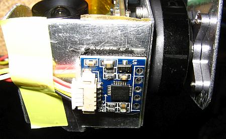
Between the camera and the transmitter I inserted an OSD module
(on-screen display), to superimpose telemetry information on the
downlinked video signal. I ordered a MinimOSD for this, the
version in a plastic box, which cost $10.
A quadcopter needs to tilt at various angles all the time, to control
its position and speed. So to get stable video it's essential to use a
gimbal. But I couldn't find any ready-made gimbal small enough to use
with the Runcam 3 Split. Using a standard gimbal intended for action
cameras is of course possible, but is much heavier than necessary, and
weight is the enemy of everything that needs to fly. So I decided to
build my gimbal from parts. Shopping for gimbal controllers, I found
that the Alexmos controllers are the most popular, and that the world
is divided basically in two big camps: The modern, high performance,
high $$$ camp, using the 32 bit Alexmos controller for 3-axis gimbals,
and the low cost camp, using various clones of the older 8-bit Alexmos
controller, which by default controls 2 axes only, but can be upgraded
to 3-axis operation. The price difference is large, so I bought an
8-bit Alexmos controller with sensor for $10.23, and
considering
that I don't need to yaw the camera, I did not add the 3rd axis module.
And I also bought two very nice gimbal motors, the Yuneec 2715, for
$14.97 total. These motors are smaller and much lighter than most
gimbal motors, and work and look really great! I haven't seen better
made motors anywhere so far.
To receive the FPV video on the ground, the most recommended approach
was to use "virtual reality" goggles with a suitable diversity
receiver. Again the world is split between a high performance, high $$$
camp mostly promoting FatShark products, and the cheapskate camp using
products that cost only a small fraction of a FatShark item. Although
the goggles are not at risk if my drone flies away or crashes, I didn't
want to pay more money for the goggles than for the entire drone plus
everything else on the ground, and this had me looking closely at the
cheapskate camp's offers.
For a primer, I wear glasses. I have strong astigmatism, very different
in both eyes, so I don't see a thing without my glasses, and for
this reason
any
goggles that cannot be worn over my glasses are out. Some
goggles
accept prescription lenses, stupidly called "diopters" (really a
measurement unit for lens strength) by many people, but these are
usually expensive
and
hard to get. So I looked only at FPV goggles that were advertised as
being compatible with normal spectacles.
Of these, the Eachine EV-800D were most highly recommended on various
websites, so I bought those, for $100.43, the most expensive
part
of my whole setup! These goggles are of the box type, have a resolution
of 800×480 pixels, support NTSC and PAL, in 4:3 or in 16:9 aspect
ratio, have a built-in diversity receiver for 5.8GHz, come with two
antennas that are said to be good, they can record the received video
on an SD card, can play back video, can accept external video, and come
with a built-in battery and a charger. The ads stress that they fit
easily over the user's spectacles. And that's the lie of the century,
my dear readers! They do not! Absolutely not! No way!!! More about that
later. Much more, in fact!
Anyway, that completes my purchases, not counting some general items
such as screws, double-sided adhesive tape, cable ties, which I also
ordered at this time, but which are not exclusive for my drone project.
 All
the above sums slightly over $600. Not cheap, but way cheaper than
buying a comparable drone setup ready-made! And much more fun, highly
modifiable, and very versatile.
All
the above sums slightly over $600. Not cheap, but way cheaper than
buying a comparable drone setup ready-made! And much more fun, highly
modifiable, and very versatile.
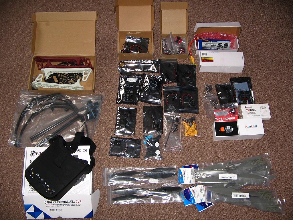
I placed the orders in early February 2020, in the midst of the
COVID-19 lockdowns in China. This delayed the shipping of several
items, since the sellers were in lockdown, or the factories couldn't
deliver due to logistic problems. And when the items started coming
in, COVID-19 had reached Chile. The city where I have my P.O.Box went into
lockdown, and all this meant that I got the last parts only by October!
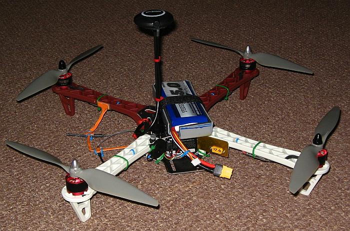
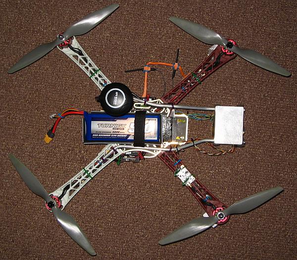
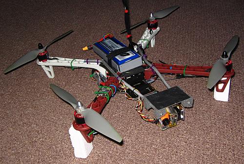
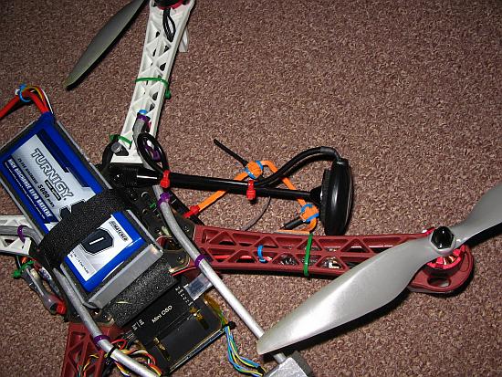
This photo shows what had arrived by mid March, the last time I could
go
to the post office before the lockdown. Most parts actually had arrived by
that time! There is the frame, the
goggles, the Pixhawk kit, the ESCs, motors, batteries, XT60 connectors, the
gimbal controller, gimbal motors, MinimOSD, video TX, antenna, the camera,
and the propellers. But a few essential items, such as the remote
control
set, didn't arrive before the lockdown.
So I went to play with the new toys, doing what I could, enjoying the
trip, because the
goal of First Flight was still far away.
I didn't like the frame at all! It proved much heavier than the ads
said. The ads claimed a total weight of 280g, but it turned out that
the weight is 312g without the landing gear, and an additional
226g for the landing gear! This has such a serious impact on the total
weight budget, that something had to be done.
The landing gear is extremely large, far too tall for this drone. It
would be easy for the drone to flip over and crash the props into the
ground when landing with even a small horizontal speed. It also
doesn't fit the frame very well. So I decided quite soon to not use the
landing gear at all.
The frame isn't very stiff. Particularly the torsional stiffness of
the arms is poor. This becomes important if there is any dynamic
imbalance in the propellers - and there always is some!
Also the frame isn't very well suited for attaching all the stuff I
need to mount. There is really no good place for the battery. Some
people mount the battery inside and the controller on top, but my
battery doesn't fit inside, in a proper way. It would end up jammed
between the arms, without any cushioning, putting it at great risk.
Placing the battery
under the drone puts the center of gravity too low, drastically
limiting the maneuvering capabilities of the drone. Putting it on top
is still
the best option, but that means mounting the controller inside the
frame, where it is hard to access, and close to the motor power wiring,
causing strong interference to its internal magnetometer. And since the
GPS mount needs to go
on the top too, there is some conflict between it and the battery.
The arms are massively made from relatively soft plastic. They are
heavy, too flexible, at the same time more break-resistant than
necessary, given that they mount with tiny 2.5mm screws, which
concentrate the forces. In a crash, breakage will probably occur around
the screw locations, and the heavy weight in plastic along the arms is
a waste.
Everything taken together, I strongly dislike this frame. For several
weeks I wondered whether I should use it at all, or put it aside and build a wooden frame.
Finally I decided to use it, without the landing gear, to assemble an
Ugly Bird and learn the basics about quadcopters, find out which parts
work and which need to be replaced, and later build my own
frame
for a version #2 of my quadcopter, using an optimized set of parts.
 So
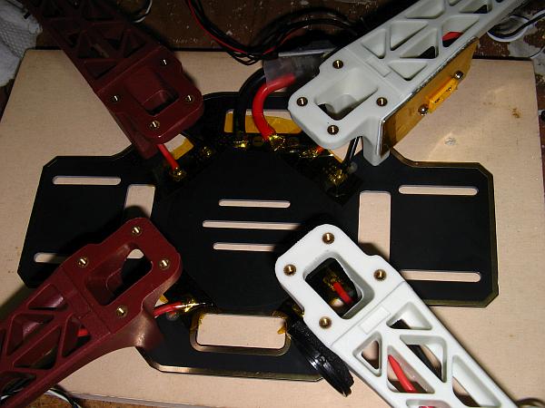
I started building. The lower center plate of the F450 frame is a
printed circuit board used for power distribution. Here you can see the
power wires of the four ESCs soldered to that board, and also the power
unit, installed between the board and a chassis-mount XT60 connector
which I installed on a small aluminium plate mounted with double-sided
foam tape to the rear right arm.
So
I started building. The lower center plate of the F450 frame is a
printed circuit board used for power distribution. Here you can see the
power wires of the four ESCs soldered to that board, and also the power
unit, installed between the board and a chassis-mount XT60 connector
which I installed on a small aluminium plate mounted with double-sided
foam tape to the rear right arm.
What on earth motivates the fashion of making so many things black?
Many parts
of my drone are black. The two boards of the F450 frame, all plastic
boxes of the Pixhawk kit, and several other parts. Black makes it hard
to see properly what one is doing, and also makes it hard to shoot
decent photos! I often find myself shining my most powerful desk lamp
directly into some corner of black stuff with black background in this
drone, and still
having trouble seeing!
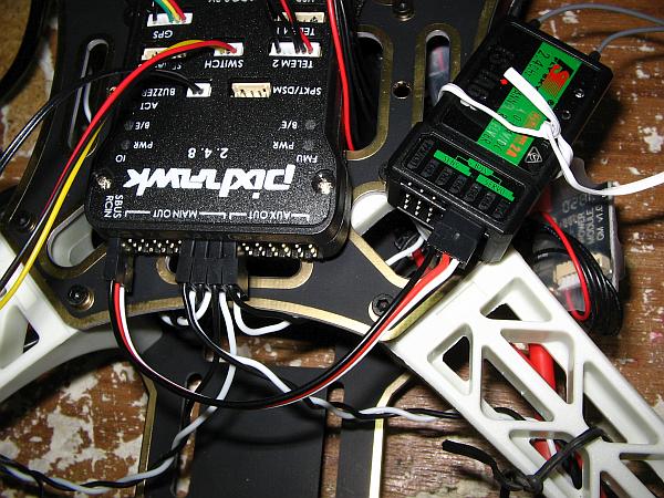 At first I installed the Pixhawk and the RC receiver on the top of the
frame, in a very temporary way, just to check their basic
functionality. The receiver is connected to the Pixhawk by a
3-conductor cable: Ground, power and data. The individual channel
outputs aren't used. The data format in use is S.Bus.
At first I installed the Pixhawk and the RC receiver on the top of the
frame, in a very temporary way, just to check their basic
functionality. The receiver is connected to the Pixhawk by a
3-conductor cable: Ground, power and data. The individual channel
outputs aren't used. The data format in use is S.Bus.
The receiver is configured from the transmitter, through its
touch-screen. It is even possible to update the receiver's firmware
through the transmitter. All these things were a total novelty to me,
after having been away from the model aircraft world for a quarter of a
century! When I stopped flying model aircraft, the RC systems didn't
use any firmware, and the airplanes had no flight controller...
As much as I like this radio control set, it does have one big fault:
There is no way to see the received signal strength! The receiver
doesn't send an RSSI (received signal strength indicator) signal on the
serial data stream, and despite the communication between the RC
transmitter and receiver being bidirectional (both are in fact
transceivers!), RSSI isn't transmitted down to the transmitter! So
while
flying one never knows how good or how bad the RC signal is getting to
the drone.
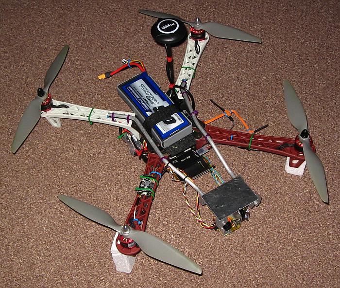
 After
initial checkout, I assembled the basic drone in a way better suited for flying: The
Pixhawk inside the frame, the receiver on the side opposite to where
the power module is, and the battery on top, in a specially made
battery holder.
After
initial checkout, I assembled the basic drone in a way better suited for flying: The
Pixhawk inside the frame, the receiver on the side opposite to where
the power module is, and the battery on top, in a specially made
battery holder.
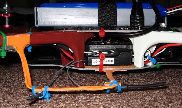
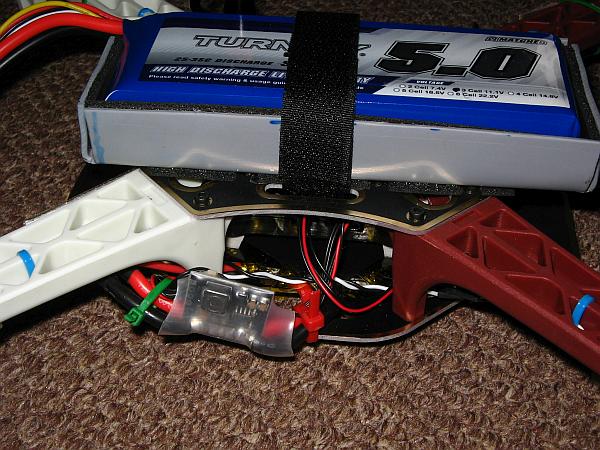
Making stuff from PVC pipe is easy! I took a piece of PVC
sanitary
pipe, slitted it, softened it with a hot air gun, flattened
it between two flat plywood pieces,
then used the PVC sheet to make the battery holder, by cutting out
a suitable shape and bending it with the hot air gun. This
battery holder was stuck to a surface of double-sided adhesive foam
which I put on the top of the frame. A velcro strap secures both the
battery and the holder to the frame, while the adhesive foam keeps the
holder from shifting around. And to balance the drone, the battery
holder can easily be lifted off, and put back down in the proper
location.
A question was how to install and orient the two RC receiver antennas.
They should always have a free line of sight to the transmitter, so
they obviously should go on the bottom side of the drone. To make good
use of receiver diversity, they should be oriented at 90° to each
other, and have some physical separation. And of course they should be
as far away as possible from parts and wiring that radiate
interference! This precluded tying the antennas to
the frame
arms, a mistake many drone builders do. The arms also carry the
ESCs and their wiring, which generates a lot of radio noise. The further away the antennas are placed, the better. So I took a
piece of orange PVC electrical conduit pipe, slitted and flattened it,
and crafted it into the fancy antenna holder you can see in this photo!
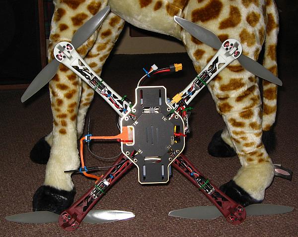
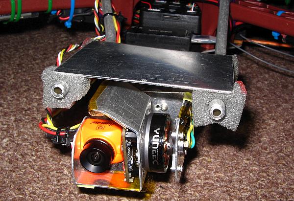
 Seen
at this angle, both the battery holder and the RC antenna holder can be
seen a little better. You can also see the GPS+magnetometer module mounted on
its very high
pedestal. This is really higher than necessary for the GPS, but the tall pedestal
is useful to put the magnetometer well away from motor wiring interference, and
that's an important point.
Seen
at this angle, both the battery holder and the RC antenna holder can be
seen a little better. You can also see the GPS+magnetometer module mounted on
its very high
pedestal. This is really higher than necessary for the GPS, but the tall pedestal
is useful to put the magnetometer well away from motor wiring interference, and
that's an important point.
For storage and transport the GPS mast can be flipped over, and then
rests at the side of one arm.
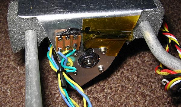
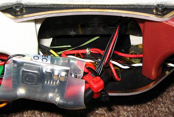
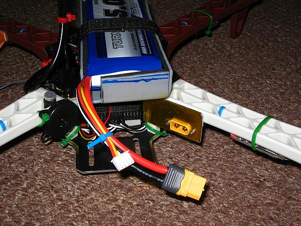 Here
is a close-up of the rear side, showing the power connector on its
kapton-covered aluminium plate. At the left you can see the pushbutton
and the buzzer. You can also see the Pixhawk's rear end, where the
connections for the radio, the ESCs and any auxiliary outputs are.
Here
is a close-up of the rear side, showing the power connector on its
kapton-covered aluminium plate. At the left you can see the pushbutton
and the buzzer. You can also see the Pixhawk's rear end, where the
connections for the radio, the ESCs and any auxiliary outputs are.
I didn't use the anti-vibration mount that came with the Pixhawk. I
found it too heavy and much too stiff. Instead I mounted the Pixhawk
using four little closed-cell PVC foam blocks, which I cut from 3M
Exterior Foam Tape Weather Strip. This seems to work better and is much lighter.
While installing the wires to the Pixhawk I made sure to use wide
enough loops, so that the wires transmit as little vibration as
possible.
 The
right side of my drone's center area is for power distribution. In this
photo there is just the power module, but later I added the BEC for the
servo rail there, and the connections for the video system's power
supply.
The
right side of my drone's center area is for power distribution. In this
photo there is just the power module, but later I added the BEC for the
servo rail there, and the connections for the video system's power
supply.
The USB connector of the Pixhawk is on this side too, which
requires leaving a clear area large enough to plug in the USB connector
for parameter setup.
 This
is how the basic quadcopter looked from the bottom side at this stage. Not much
there yet! Later I
installed all the gripper and the gimbal, using up that space.
This
is how the basic quadcopter looked from the bottom side at this stage. Not much
there yet! Later I
installed all the gripper and the gimbal, using up that space.
My thanks go to Euridiiice the giraffe for holding up the copter for
this photo. Her name is spelled with those three letters "i", to do
justice
to her long neck, which I had to cut off to make the photo fit on this
page.
In this condition the drone was ready to fly. I first did the whole
setup of the flight controller, very carefully. Arducopter is a
complex, quite advanced software that has a lot of features, many
configuration parameters, and it really needs to be set up correctly to
work. So it's not for the kind of people who like to take something out
of a box and fly it. It's not for those who abhor reading and following
instructions. There is very good documentation online, and one
really has to read it, digest it, understand it, read it again - and follow it! At least most of the time...
I went through it step by step, trying to test as many things as I
could with the drone inside my workshop, properly tied down whenever
the propellers were installed. Despite being pretty confident that I had done
everything right, I did the first flight with a 10m long leash tied to
the drone, its other end tied to a brick! I had a very bad experience
previously with a toy drone, a Syma X25-Pro, which had a huge
predilection for flying away. It would suddenly just shoot up
and
away, not reacting to any control input, only to be
caught by a helpful tree! And I had read that this also
happens
with Arducopter-controlled drones, when they are incorrectly set up, or
if they suffer from excessive vibration. So, better safe than sorry! I made
sure that my brick was heavy enough so that the drone absolutely
couldn't fly away with it!
But my caution proved unnecessary. The Ugly Bird flew quite nicely on the
first try, very stably, without any tendency to do unexpected tricks.
So for the next flights I released it from the leash, and stored my
brick for future uses.
Multicopter control software contains several servo loops, which use
adjustable PID (proportional+integral+derivative) gain. The
Arducopter software comes with default parameters that usually result
in a
stable and safe, although somewhat sluggish response. My Ugly Bird flew
just as intended by the software developers: Very stably, although
having the reactions of an old man rather than those of the young kid
it is. To correct this, the parameters can be tuned manually or
automatically. The latter option is highly attractive, because it's
easier to do and will result in optimized parameters that make the drone
follow control input in a snappy and precise way. So I tried
autotuning, but it failed. There can be many reasons for failure. Since
my drone was flying well enough for first tries with the default
parameters, I decided to leave the parameters alone for the moment, and start
adding payload to the drone. PID tuning could be optimized later, to improve the response.
Camera installation
At first I installed the camera without a gimbal, in a soft foam mount
at the front of the drone, suspended from two plastic tubes protruding
forward. I forgot to shoot photos of this setup, so I can't
show you any! Sorry about that. This provisional installation served to
find out that the absolutely softest mount works best. It has to be so
soft that it barely holds the camera in the rough direction intended.
Otherwise vibration from the propellers will cause a really terrible
"jello effect", the name droners give to the shaking-jelly-like
deformation of the video image caused by the rolling shutter of a CMOS
image sensor that's vibrating. I ended up mounting the camera with blocks of very soft foam.
The testing also showed that the transmitter and the OSD work fine,
and that the camera's image quality is nothing to write home about...
And also it made clear that a gimbal is really necessary, to avoid
getting seasick while watching the video. So I won't dwell any longer
on this provisional installation, and move right on to the gimbal-based
installation that I'm using at the time of writing
this page.
 The first problem to be
handled is that the Runcam Split 3 is, well, a split camera. The camera
head is very small, and it's connected to a somewhat larger printed
circuit board through multiple, flexible, very thin wires, with their
connectors glued to the board. The cable is much too short to bring it
out of the gimbal, forcing me to install the board in the gimbal along
with the camera head.
The first problem to be
handled is that the Runcam Split 3 is, well, a split camera. The camera
head is very small, and it's connected to a somewhat larger printed
circuit board through multiple, flexible, very thin wires, with their
connectors glued to the board. The cable is much too short to bring it
out of the gimbal, forcing me to install the board in the gimbal along
with the camera head.
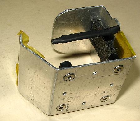
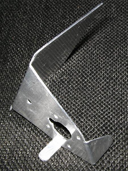
To do this, I found some scrap of 1mm thick aluminium sheet,
and
crafted the
bracket shown here. It's designed to take up the complete
Runcam Split 3 Micro, protecting it somewhat, while allowing
easy
access to its
SD card slot and to its buttons.
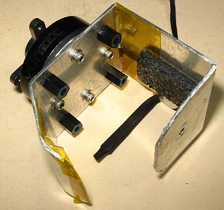 On the rear side the
bracket attaches directly to the tilt motor. That's why the screws
holding the camera board's standoffs need to be flat headed.
On the rear side the
bracket attaches directly to the tilt motor. That's why the screws
holding the camera board's standoffs need to be flat headed.
To assemble this, first the standoffs are installed, then the bracket
is attached to the motor, then the camera board is installed in the
bracket, and finally the camera head. It's all very compact, because
compactness leads to stiffness and lower weight.
The center line of the motor runs exactly through the mass center of
the bracket with the camera installed, the SD card inserted, and the gimbal sensor attached to the bottom. This has
to me measured before drilling the holes for the motor! The motor ends
up a little bit shifted from the physical center of the bracket.
These motors use very small screws! They are M1.6, that is,
their nominal outer diameter is a little less than 1.6mm. They are 4mm
long.
The standoffs are M2, the screw holding the camera head too. Most other
screws on the drone are M2.5. Since I normally worked with
screws sized M3 and larger, and local stores also offer only M3 and
larger, I had to buy kits of M1.6, M2 and M2.5 screws from China, and a
kit of M2 standoffs.
Note that all areas where the board edge or any wire can touch, are
insulated with kapton tape or heatshrink tube. A piece of damping foam
goes between the camera head and the bracket, to attenuate any resonances.
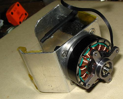 Since it's so nice, here
is a view of the bracket from the motor side. These Yuneec
motors are really beautiful!
Since it's so nice, here
is a view of the bracket from the motor side. These Yuneec
motors are really beautiful!
In the background is the camera, waiting to be installed.
By the way, Yuneec seems to measure motors differently from most
manufacturers. While my flight motors are size 2212, meaning that their
stator (inside the rotor) has a diameter of 22mm and a height of 12mm,
these Yuneec 2715 motors are measured externally. Their total external
diameter is 27mm, and their total length between the two mounting
surfaces is 15mm. So the Yuneec 2715 motors are significantly smaller
than the Readytosky 2212 motors. Their diameter is only slightly smaller,
but they are much shorter and thus lighter than the flight motors.
Also it's important to know that gimbal motors have a very low KV
rating. This "KV" has absolutely nothing to do with "kilovolt"! It
means a constant of theoretical revolutions per minute per volt, when
free-running. So my flight motors, rated at KV=920, when free-running (without
propellers) at full throttle with a 12V battery, should rotate at 11040
RPM. Loaded with propellers it's significantly less.
The Yuneec gimbal motors have KV=180. For a given stator
lamination stack and rotor, the KV value is determined by the amount of
wire turns wound on the stator. More turns produces a lower KV rating,
also requires thinner wire, making a motor that runs slower at a given
voltage but needs less current to develop a given torque. This
lower current requirement is why low KV motors are used in gimbals. A
gimbal motor needs to rotate only as fast as the maximum rolling or
tilting rate of the drone, and that's very slow compared to the speed propellers run at.
To make such aluminium sheet pieces without having to do too much
precision measuring and marking, I design the pieces in AutoCAD, print
them on paper, stick the paper to my piece of aluminium sheet using
double-sided adhesive tape, and then I mark, cut and drill through the
paper and the aluminium. Then I make the bends, and after that I remove
the paper, countersink any holes that need it, and deburr
the piece.
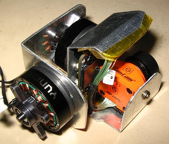 This photo brings news!
The camera has been temporarily installed, and the second
bracket is in place,
along with the roll motor.
This photo brings news!
The camera has been temporarily installed, and the second
bracket is in place,
along with the roll motor.
The second bracket is very simple, but I got the mass
center measurement wrong, and
the roll motor ended up a few millimeters shifted relative to its
correct position. So I had to drill new holes
for it. You can see one of the surplus holes here... No big
deal.
When building a gimbal its important to keep everything well balanced,
because any imbalance will transform linear vibration into torsional
one. While linear vibration doesn't cause any blurring or jello effect
with distant objects, torsional vibration does. While the gimbal
controller will tend to cancel torsional vibration, it cannot do
this perfectly, so it's always best to start with a precise mass
balance.
 I installed the gimbal controller's inertial motion sensor under the
camera bracket, using double sided foam tape. This exposes the sensor
to possible contact with conducting objects, which I don't like, but I
have been getting used to the fact that the electronics of drones built
on open frames live dangerous lives!
I installed the gimbal controller's inertial motion sensor under the
camera bracket, using double sided foam tape. This exposes the sensor
to possible contact with conducting objects, which I don't like, but I
have been getting used to the fact that the electronics of drones built
on open frames live dangerous lives!
The sensor board can be mounted in any position, as long as it is
exactly perpendicular to the motor axes. Later, during setup of the
gimbal software, the sensor orientation is declared.
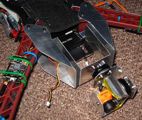 I tried to
install the gimbal on the drone using the aluminium bracket system
shown here, with foam blocks to attenuate vibration. This supports the
gimbal very much behind its mass center, causing a lot of
linear-to-torsional vibration transformation. I hoped to get away with
this thanks to the very soft foam mounting, but it didn't work! The
first flight test with the gimbal installed in this way produced a
disastrous video quality! It had the worst jello effect I
have ever seen.
So, despite my beautifully crafted, computer-designed scrap aluminium
mounting brackets, each of
which attaches to 4 screws of the drone frame, giving a very
solid mount and two well aligned, vertical, parallel mounting surfaces,
I had to discard this approach and find one that mounts the gimbal in
its
mass center, at least for the yaw axis. The roll and tilt axes are less
critical in this regard, because the gimbal can compensate for vibrations
in those axes to some degree. A three axis gimbal would be better in
this regard, but also heavier.
I tried to
install the gimbal on the drone using the aluminium bracket system
shown here, with foam blocks to attenuate vibration. This supports the
gimbal very much behind its mass center, causing a lot of
linear-to-torsional vibration transformation. I hoped to get away with
this thanks to the very soft foam mounting, but it didn't work! The
first flight test with the gimbal installed in this way produced a
disastrous video quality! It had the worst jello effect I
have ever seen.
So, despite my beautifully crafted, computer-designed scrap aluminium
mounting brackets, each of
which attaches to 4 screws of the drone frame, giving a very
solid mount and two well aligned, vertical, parallel mounting surfaces,
I had to discard this approach and find one that mounts the gimbal in
its
mass center, at least for the yaw axis. The roll and tilt axes are less
critical in this regard, because the gimbal can compensate for vibrations
in those axes to some degree. A three axis gimbal would be better in
this regard, but also heavier.
 So, back to cutting and
bending aluminium sheet...
So, back to cutting and
bending aluminium sheet...
It would have been best to mount the gimbal at two spots, such
that the average mounting force is exactly at its mass center in all
three axes. Since I can't put a mount on the front, because the camera
needs to look in that direction, and neither can I put a mount under
the gimbal, because the camera needs to look straight down too, the
most obvious option would be to place one mount on each side of the
gimbal. But
that would have made my gimbal too wide, putting too much of it
directly under the front propellers, which would have reduced propeller
efficiency
and put lots of turbulence on the gimbal. So I decided to hang the
gimbal from the top, with a mount that at least is in the mass center
for the yaw axis, although not for roll and tilt.
This bracket attaches to the roll motor, and has a top "roof"
mounting plate that is centered above the gimbal's mass center. It
allows hanging the gimbal from the top, while also providing some shielding of the
gimbal's movable parts from the propeller turbulence.
A future incarnation of my drone will have a wider separation between
the front propellers, and a body that fully shields the gimbal from
turbulence.
That would allow supporting the gimbal from both sides, so that the
average support force ends up in the mass center for all three axes.
 Since aluminium sheet
mounting brackets long enough to attach to the new gimbal rear bracket
would have been too large, putting too much surface in the propeller's
airstreams, I opted for a quick and dirty solution: I took some 6mm
thick soft aluminium tubing, and bent it into the shapes needed to
allow attaching it to the frame by means of cable ties and double sided
foam tape, while providing support for the gimbal at the proper
location.
Since aluminium sheet
mounting brackets long enough to attach to the new gimbal rear bracket
would have been too large, putting too much surface in the propeller's
airstreams, I opted for a quick and dirty solution: I took some 6mm
thick soft aluminium tubing, and bent it into the shapes needed to
allow attaching it to the frame by means of cable ties and double sided
foam tape, while providing support for the gimbal at the proper
location.
The two aluminium pipes are asymmetrical, in order to locate the gimbal
assembly somewhat left from the drone's center line. This serves two
purposes: It places the camera head closer to the center line, so that
there is less tendency for one propeller to intrude into the
image during high tilt maneuvers; and it places the gimbal's weight a
little left, allowing me to move the battery holder a little to the
right to counterbalance the gimbal. This was desirable because the
battery mount was in direct contact with the GPS pedestal fixing
sleeve, difficulting its use.
I had to move the battery holder pretty far back to counterbalance the
gimbal. The right rear propeller passes just a few mm from the battery
corner. Thanks to the battery holder being firmly held in place by
the sticky foam tape, there is no risk of collision.
And the battery cable of course is plugged into its socket
during flight, eliminating any risk of propeller contact. The gimbal
and camera cables are safely below the propellers. They aren't
long enough to get into harm's way.
 I mounted the gimbal's top plate to the aluminium tubing using soft
foam blocks. They are simply perforated and pushed over the
tubing, then
stuck to the aluminium sheet using double-sided tape.
I mounted the gimbal's top plate to the aluminium tubing using soft
foam blocks. They are simply perforated and pushed over the
tubing, then
stuck to the aluminium sheet using double-sided tape.
Unfortunately my tape doesn't stick very firmly to this foam. If subjected to a
pulling force,
it will slowly come off! So if I place the drone upside down
for too long, suddenly the gimbal will fall off... but in the
drone's normal
position, bottom down, the tape holds the gimbal in place well
enough! And it
can't come completely off the drone, of course, because several wires
tie them together.
I might improve this by drilling holes into the corners of the roof
sheet,
and using larger foam blocks with slits in them, pulled through these
holes.
As you can see, the clearances between all parts are pretty tight. I
did this to minimize weight and levering. The price is that the roll
compensation range is only about ±25°, but this is enough for normal
flying. The gimbal hits the end stops only during unusually brisk
maneuvers. The tilt axis has a range from about 15° up from horizontal
to 40° behind straight down. It's not useful to have more than 15°
upward tilt with the camera mounted in this place, because that would serve
just to film the propellers... With the camera in horizontal orientation,
the right propeller does intrude a little into the image during a
strong forward tilt plus right roll maneuver, but that can be avoided
in most flying conditions by being gentle on the control stick. When tilting the camera a little down, so as
to place the horizon line in the upper third of the image, the
propellers never intrude.
Most older multicopters have their cameras installed under them, rather
than in front. I guess that this is done mainly to allow carrying heavy
cameras, that can't be balanced when installed in front. But with a
lightweight camera, like this Runcam, a frontal location seems better
to me. It allows looking forward and down, and doesn't require adding a
large landing gear, which is somewhat heavy and tends to make the drone
unstable on the ground. Also placing the camera under the drone, plus
adding that landing gear, shifts the mass center far below the thrust
center, forcing a battery placement well above the propeller plane to
keep balance. Many drone builders don't do the latter, maybe don't even
understand the problem of vertical mass balance! A drone that has its
mass center much below its thrust center will be fine while hovering
with no wind, but will have very little ability to fly fast or to
compensate for strong wind, because any tilting or rolling of such a drone
requires two motors to work much harder than the other two, easily
running out of power reserve. So it's always better to keep a drone
well balanced, even in the vertical plane. Fixed-wing airplanes get
more stable and safer when the mass center is lower and forward
relative to the lift center. Multicopters don't.
The Ugly Bird anyway couldn't carry a camera under it, because that area is reserved for the gripper!
 The
Yuneec motors come with very thin wires terminated in small connectors.
To avoid the risk of ripping these wires out of the motors, and since I
couldn't use those connectors anyway, I cut the connectors off and
soldered the wires to little pieces of printed circuit board stuck to
the brackets. There I attached somewhat more robust ultra flexible
silicone-insulated wires.
The
Yuneec motors come with very thin wires terminated in small connectors.
To avoid the risk of ripping these wires out of the motors, and since I
couldn't use those connectors anyway, I cut the connectors off and
soldered the wires to little pieces of printed circuit board stuck to
the brackets. There I attached somewhat more robust ultra flexible
silicone-insulated wires.
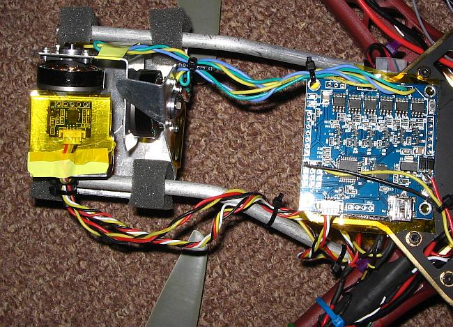 The
gimbal controller was installed under the front of the frame's bottom plate, using double-sided foam tape. In this photo the
controller is still exposed to the elements, such as wet grass, but
later I applied kapton tape insulation over it, like this photo already
shows in place for the sensor board. I also covered the frame's base
plate with kapton tape before installing the board, so that I can
repeatedly unsolder and resolder the wires without any risk of causing
a short to the board. Kapton is heat-resistant and acts as a good solder
barrier.
The
gimbal controller was installed under the front of the frame's bottom plate, using double-sided foam tape. In this photo the
controller is still exposed to the elements, such as wet grass, but
later I applied kapton tape insulation over it, like this photo already
shows in place for the sensor board. I also covered the frame's base
plate with kapton tape before installing the board, so that I can
repeatedly unsolder and resolder the wires without any risk of causing
a short to the board. Kapton is heat-resistant and acts as a good solder
barrier.
The gimbal controller connects to the gimbal motors, the sensor board,
the drone's battery, and there is also a single control signal coming
from an auxiliary channel of the Pixhawk. This brings in a feed-through
signal from one channel of my radio, which I use to tilt the camera to
any orientation between
horizontal and vertically down. I use a spring-centered
auxiliary potentiometer of my transmitter to control the tilt angle
through the gimbal controller's velocity mode. This allows smooth
vertical panning. The yaw control stick allows equally smooth
horizontal panning, of course.
I configured the radio to use channel 9 for the left thumbwheel, and
set up Arducopter so that the Pixhawk will pass the
radio channel 9 through to the output. Since there are 8 primary
(motor)
outputs on the Pixhawk, radio channel 9 appears at auxiliary
output 1 of the
Pixhawk. This is a case of RC opportunism! :-) Assigning
radio
channels and transmitter control elements to various functions, using
the options given by Arducopter software running on a Pixhawk, is a bit
like a strategic game, making use of the various possibilities and
flexibility each
part of the system has, and working around any limitations.
Arducopter can also be set up to control the gimbal more actively, but
so far I haven't found this necessary. It's one of the things left to
play with, after finishing this web page - if I ever finish it! It seems to be getting long...
 The
camera ends up hanging pretty low, which forced me to raise the
front of the drone by installing styrofoam blocks to extend its front
feet. The blocks may not be elegant, but they are cheap, lightweight,
easy to install (double-sided tape and a cable tie), and their bright white
color improves orientation visibility of the drone in the air.
The
camera ends up hanging pretty low, which forced me to raise the
front of the drone by installing styrofoam blocks to extend its front
feet. The blocks may not be elegant, but they are cheap, lightweight,
easy to install (double-sided tape and a cable tie), and their bright white
color improves orientation visibility of the drone in the air.
With longer front feet than rear feet, the drone sits tilted on a flat
surface. But this doesn't matter at all, because the accelerometers are
calibrated only in the workshop, not before taking off. The gyroscopes
are calibrated after power-on, which requires keeping the drone
motion-free
during that moment, but its attitude doesn't matter. So the drone can
take off from inclined surfaces without any problem. That's an
important point in my hilly, densely overgrown wilderness flying
location.
If a drone needs to be turned on and flown from a moving vehicle, the
gyro calibration at turn-on should be disabled in the software.
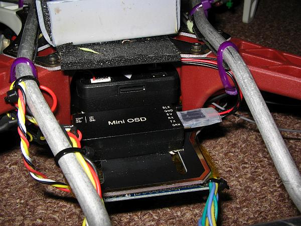 The
OSD unit is installed in front of the Pixhawk, low enough to leave free access to
the Pixhawk's SD card slot. The SD card is the "black box" of the
drone, storing detailed data of every flight. It can also store terrain
information downloaded from the internet, for flight modes that require
terrain following, but I don't use that feature.
The
OSD unit is installed in front of the Pixhawk, low enough to leave free access to
the Pixhawk's SD card slot. The SD card is the "black box" of the
drone, storing detailed data of every flight. It can also store terrain
information downloaded from the internet, for flight modes that require
terrain following, but I don't use that feature.
The MinimOSD, mislabeled "Mini OSD" on the box, is an Arduino in
disguise, connected to an OSD chip. It can be configured by unplugging
the data connector on the right, and connecting that port to a computer
via an USB to serial converter. So the OSD unit has to be placed such that
there is access to this port!
Some people run into trouble with powering the MinimOSD, because this
matter is poorly documented, and there is some wrong or
misleading
information online. The MinimOSD has two "sides". One is
the Arduino in it, the other is the OSD chip proper. Each needs a 5V
power supply. In order to try avoiding interference to the video from the
digital-side power supply, the original designer provided a method to power both
sides separately, when using a second battery to power
the whole video system independently from the rest of the drone. To do
so, the MinimOSD includes an internal 5V regulator, which gets its
unregulated input from a pin on the video side of the
module,
intended to be connected to the video battery. This regulator powers
the OSD side, while the Arduino side gets powered from the flight
controller, through a 5V input pin on the data side.
But most modern drones don't use a separate battery for the video
system! They power everything from a single battery, and so it doesn't make much
sense to separate the power supplies in the MinimOSD. To be used in this
situation, the MinimOSD board includes jumpers, cuttable traces or
solder bridge locations that
allow joining or separating the 5V lines of both sides as required. If
joined, the entire
MinimOSD can be powered either from its 5V input or from its 12V input
- but not both at the same time!
Most MinimOSD boards are delivered with these bridges already in place,
and without correct, clear documentation telling people to use either
one or the other power input, but not both. The result is that some
people end up connecting both power inputs, which makes the internal
small 5V regulator work in parallel with the drone's power module's
regulator. How much of the flight controller's supply current will then
be
delivered by the MinimOSD's little internal regulator depends
solely on their exact relative voltage outputs and the wiring
resistances in the setup, and the result is often that the MinimOSD's
regulator works far too hard with this heavy unintended load, and burns
out, or overheats the OSD chip which is located very close to it!
There are some web pages written by people who didn't really understand
this, and thought that the OSD chip proper is at fault.
In the Ugly Bird the MinimOSD has the internal 5V interconnections in place, and I'm powering it only through the 5V
input, from the
Pixhawk. The 12V input remains disconnected, and thus the internal 5V
regulator isn't used at all. It works fine, and I don't get any
interference.
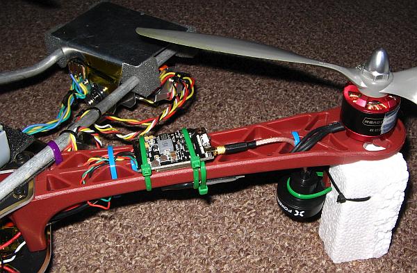 The
video signal flows from the camera to the OSD unit, and from there
continues to the video transmitter. This little unit gets so extremely
hot that I mounted it on the top of the front right arm, directly under
the propeller, creating some more drag and turbulence but getting very
good
cooling.
The
video signal flows from the camera to the OSD unit, and from there
continues to the video transmitter. This little unit gets so extremely
hot that I mounted it on the top of the front right arm, directly under
the propeller, creating some more drag and turbulence but getting very
good
cooling.
When flying in high humidity the propeller can cause condensation of
tiny water droplets, and throw some of these on the video transmitter. It
reacts by causing many brief video dropouts! So it's not a very good
idea to fly my drone in such weather. I didn't dare put any protection
on top of this board, because it gets so terribly hot! It needs all the
cooling it can get.
This transmitter is rated at 800mW. I use the high power setting only when
I will
fly at some distance, and then I take off as soon as
possible after connecting the battery. I fear that if I leave the
transmitter running at full power
without the propeller cooling it, it might melt the plastic of the frame's
arm! Whenever I'm not flying at distance, I keep the transmitter set to
25mW output power. At that level it just gets hot, but not extremely
hot... And this power level works well enough when flying at modest
distances.
Power setting, and also channel selection, are done by a single tiny
pushbutton, which looks sheepishly at the motor in this picture, beside
the antenna connector.
The Foxeer antenna was mounted on the right front foot, pointing
downwards. This puts it in direct view of the ground, in any direction,
and places it as far away as possible from the RC receiver antennas, to
minimize the risk of any interference. The two systems operate on
totally different bands, but these small cheap radio units are
typically not very well filtered and might have strong spurious
responses.
Like the camera, the transmitter can run directly from the
flight battery's voltage,
but the manual warns that this should be filtered. So I made a power
line filter and installed it under the arm, between the
transmitter and the power distribution point. Such filters can also be bought from China, at a very low price.
 The
Ugly Bird's second payload is a gripper. This is a simple
device
involving a servo that operates a sort of padlock. A load can be safely
engaged here, and released by making the servo open the lock.
The
Ugly Bird's second payload is a gripper. This is a simple
device
involving a servo that operates a sort of padlock. A load can be safely
engaged here, and released by making the servo open the lock.
I used a piece of profiled wood, carved to shape, and a piece of steel
wire, to fashion this padlock. I mounted it - how else - by using
double sided tape and cable ties...
The load ends up hanging precisely under the drone's center of lift,
and is released when the servo pulls the wire back.
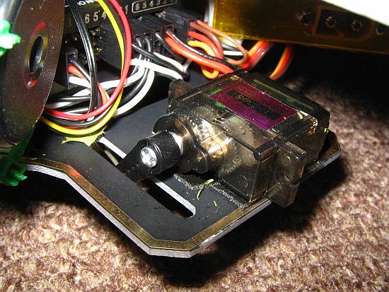 The
servo rests on the top side of the frame's bottom plate, at rear, its
arm
extending through a cutout that happened to be very conveniently
placed, despite being intended for some totally different use.
The
servo rests on the top side of the frame's bottom plate, at rear, its
arm
extending through a cutout that happened to be very conveniently
placed, despite being intended for some totally different use.
The servo is mounted - you guessed it - with double-sided tape.
Implementing a variation of this theme, I used no cable tie this
time! :-)
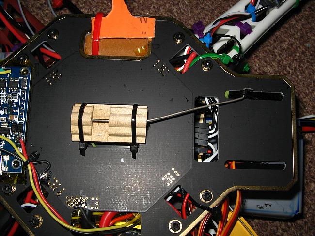
 Here
is a new view of the power distribution side of the drone's center
area. The BEC that powers the servo rail has been added, directly
behind the power module. This BEC not only powers the gripper servo,
but it also acts as redundant 5V source for the Pixhawk.
Here
is a new view of the power distribution side of the drone's center
area. The BEC that powers the servo rail has been added, directly
behind the power module. This BEC not only powers the gripper servo,
but it also acts as redundant 5V source for the Pixhawk.
Deep inside you can see two of the light gray colored foam pads that
support the Pixhawk. And if you look very carefully into this murky
black mess, you can even see the Pixhawk's micro USB connector. That's
where I have to plug in the computer every time I need to change any of
the Pixhawk's configuration parameters, and that's why some people
prefer to use the USB extension unit that comes with the Pixhawk kit,
and mount it in some easily accessible place, despite its
additional weight.
 Here
is a photo showing how the GPS support mast folds down for storage.
It's also convenient when placing the drone upside-down to work on its
bottom side. It will then rest on the propeller nuts.
Here
is a photo showing how the GPS support mast folds down for storage.
It's also convenient when placing the drone upside-down to work on its
bottom side. It will then rest on the propeller nuts.
Interconnections
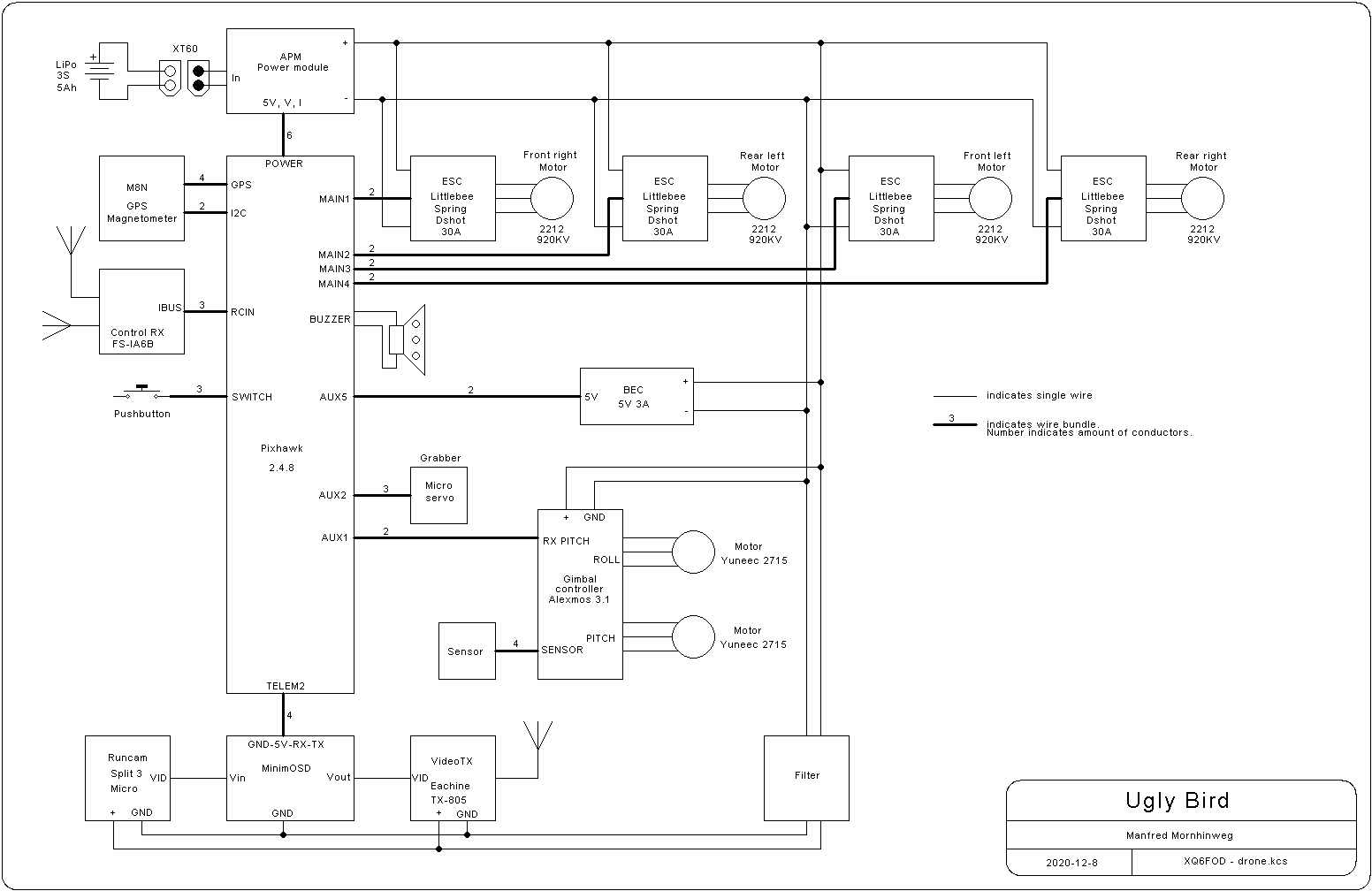
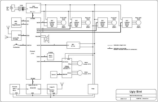 A
newcomer to drones will surely wonder how all these parts and
modules interconnect. The best way to show it is with a block diagram.
Click it to get a legible version!
A
newcomer to drones will surely wonder how all these parts and
modules interconnect. The best way to show it is with a block diagram.
Click it to get a legible version!
As you can see, it's not really complex. The battery, Pixhawk, ESCs,
flight motors, and either the power module or the BEC are absolutely
essential. Everything else is optional to some extent! A drone can fly
without a GPS and using the Pixhawk's internal magnetometer. If it has
a GPS, it can fly without an RC receiver, performing pre-programmed
autonomous missions. The beeper and pushbutton are there just for
convenience, and
while I find the beeper useful, I definitely don't need the pushbutton,
and would remove it if that wouldn't require tearing down half of the
drone. Everything else is payload: Gripper servo, camera, video
transmitter, OSD, the filter powering them, and the gimbal.
While the Ugly Bird is a simple animal, there is no limit to how much
complexity could be added. A copter can have 6 or 8 or even more flight
motors and ESCs. It could use two or more batteries,
additional
power modules, additional inertial motion sensors, an ultrasonic altimeter,
collision avoidance cameras, a ground-lock camera for precise position
control, a recovery parachute, retractable landing gear, more
sophisticated gimbal control, the camera and video transmitter could be
controlled from the Pixhawk, there could be a backup RC receiver, of
course one could add a telemetry radio that links the drone to the
groundstation software during flight, and the possibilities for fancy
payloads are unlimited.
I have no idea yet what I will be adding to the drone over time. But
due to the high risk of complete loss involved in flying over my
densely wooded area, I don't want to put very expensive stuff on the
drone, nor do I want to make the drone proper much larger - and
carrying much more stuff does require a larger drone!
Some people have asked me why I used a 3S (3 cells in series) battery.
Apparently they tend to think that more is always better. I did this
for two main reasons. One is that the accessories, like the gimbal,
camera and video transmitter, can work fine from a 3S battery, while 4S
might already be too much, requiring transient limiters or even an
additional voltage regulator. So a 3S system is simpler
and more efficient. And the other reason is that a 3S
battery
produces
just the right amount of peak thrust for a drone of this size, when
using widely available 2212 KV920 motors and 1045 propellers. Using a
4S battery would require motors rated at lower KV, which are less
common, or smaller propellers, which are less efficient, or it would
result in a drone that can consume such high peak current in an extreme
maneuver that it might overtax the the battery or the motors.
Bigger isn't always better. Sometimes a specific size is just
right.
Propeller grief
The intense jello effect I got at first was a clear indication that my
drone suffered from extreme vibration. I used my homemade accelerometer to
measure the vibrations, and found that each individual propeller caused
vastly different amounts of it. This set me on a course of trying to
balance my propellers, and also my motors.
Motor balancing was easy: Using a method described on the web, I
empirically did a decent dynamic balancing of each motor by sticking
little pieces of tape to one or two spots of each runner. This
brought the motor-induced vibrations down to almost zero,
but they were never very big to start with.
Propeller
imbalance is a much more serious problem. Unfortunately many websites
describe methods for static propeller balancing only, and stores sell
propeller balancing devices that also are good only to do static
balancing. But propellers are three-dimensional parts, and absolutely
need to be in good dynamic balance to run without causing too much
vibration! The idea promoted by some people, that propellers are flat
enough to only need static balancing, is totally incorrect. Even if a
propeller was perfectly flat and straight and was in perfect static
balance, all it takes to cause strong dynamic imbalance is a
very small tilt of the propeller relative to
the motor axis! Such tilt can
be caused by an imprecisely formed hub contact surface, a slightly
crooked hole, a grain of dust between the prop and the motor, by the
propeller bending slightly after being made.
Most quadcopter propellers are injection-molded, and it's hard to make
parts by this process that come out really straight, and stay straight.
Despite this need for dynamic balance, there don't seem to be tools for
true dynamic balancing of drone propellers. Homebuilt balancing setups
are described on some web pages, but shockingly they don't perform
dynamic balance! The authors seem to think that two-dimensional
balancing in a spinning setup is the same as dynamic balancing!
Maybe someday I will build a true small-scale dynamic balancer. For
now, all I can do is accurate static balancing, and empirical dynamic
balancing, based on guessing the locations where to add mass and then
measuring the total vibration that results, as a scalar value.
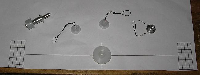 Being the proud owner of a lathe, I made several simple tools to check
the static balance and straightness of my propellers. Top left is a
traditional roll balancer, which also can be bought ready-made in
various types. Then come three hang balancers, two made from technyl
and one from aluminium, having various sensitivities. And the printed
paper with the technyl hub glued
on is a straightness checker tool.
Being the proud owner of a lathe, I made several simple tools to check
the static balance and straightness of my propellers. Top left is a
traditional roll balancer, which also can be bought ready-made in
various types. Then come three hang balancers, two made from technyl
and one from aluminium, having various sensitivities. And the printed
paper with the technyl hub glued
on is a straightness checker tool.
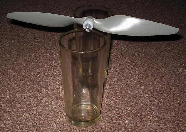 This
is a way to use the roll balancer. It needs to be placed on two very
smooth, completely flat and leveled, hard surfaces. I used two drinking
glasses
for
this photo, but two very straight, polished round bars are better. It
is critically important that the rolling supports are perfectly
leveled, or the balancer will always tend to roll to one side. My
glasses placed on a carpet definitely don't meet that requirement!
This
is a way to use the roll balancer. It needs to be placed on two very
smooth, completely flat and leveled, hard surfaces. I used two drinking
glasses
for
this photo, but two very straight, polished round bars are better. It
is critically important that the rolling supports are perfectly
leveled, or the balancer will always tend to roll to one side. My
glasses placed on a carpet definitely don't meet that requirement!
The nice thing about such a roll balancer is that it always has neutral
stability, so it will be very sensitive to even slight static
imbalance. The propeller should always stop at any random position,
after having been disturbed. In this case, the propeller doesn't do
that, but tends to level
itself almost horizontally every time, always on the same side, which
means that its static blade balance is
reasonably good, but the blades aren't at 180° to each other! In
simple words, the propeller is crooked. Some people call this
a
"bad hub balance", but what's bad here is not the hub! It's the
propeller's straightness.
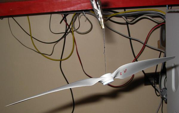 The
hang balancer has the big advantage that it doesn't
require a
straight and leveled surface to work. It's simply hung from its
string.
The
hang balancer has the big advantage that it doesn't
require a
straight and leveled surface to work. It's simply hung from its
string.
The critical points when making such a hang balancer are that the
string
should be thin and flexible, and the center hole must be very small,
just barely larger than the string, and very well centered. On the top
side the hole has a
conical enlargement, and this cone goes as deep into the hole as you
want the balancer to be sensitive! If the tip of the conical opening
ends in the exact mass center of the propeller plus balancer, then
there will be neutral stability, and the balancer will be extremely
sensitive. If the cone ends a little higher up, the sensitivity will be
reduced, and the propeller will hang at various degrees of inclination
depending on the amount of static imbalance it has. And if the cone
ends too deep in the balancer, it will be unstable, and will
always tip over to any side even if the static balance is good, making
such a balancer hard to use.
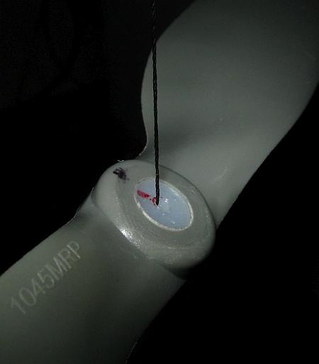 This is a close-up
of the balancer's top, with the conical enlargement of the hole visible.
This is a close-up
of the balancer's top, with the conical enlargement of the hole visible.
It's obvious that a propeller hanging at this angle is seriously
crooked, being much lighter on the side where I drew the black dot!
Counterweights can be added as needed to bring a propeller into static
balance, and this will help reduce the vibration it causes. But as long
as the dynamic balance isn't good too, a propeller will always vibrate.
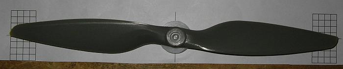 To
check the straightness of a propeller I use this tool. The drawing was
made in AutoCAD, printed on paper, and the precisely made plastic
technyl hub is glued to the paper exactly at the center of the
drawing. Then simple straight-down looking can be used to coarsely
assess propeller straightness. If a propeller is very strongly crooked,
this can be seen at
once, and those propellers thrown away or used for
decoration.
To
check the straightness of a propeller I use this tool. The drawing was
made in AutoCAD, printed on paper, and the precisely made plastic
technyl hub is glued to the paper exactly at the center of the
drawing. Then simple straight-down looking can be used to coarsely
assess propeller straightness. If a propeller is very strongly crooked,
this can be seen at
once, and those propellers thrown away or used for
decoration.
For more precise measurement of the survivors I place the whole affair
on a flat glass plate, use a precisely made cube to align one propeller tip
with a mark on the paper, and then use the cube to see where the other
tip lands on the drawing. The measurement is repeated after rotating
the propeller a half turn, and the two results averaged, to
cancel out
any imprecision of the technyl hub and the print.
And I'm sorry about having to tell my dear readers that of the 12
highly recommended
Gemfan propellers I bought, only one is straight within the limits of
my measurement capability! The other 11 ones are crooked, the worst
ones by nearly 2°! And the much more expensive HJ carbon fiber
propellers were only somewhat better in average. None of them
was perfectly straight.
I took the worst of the Gemfan propellers and attempted to
bend it
straight, by softening it with a hot-air gun, warming it up very slowly
and gently and trying to find a temperature setting at which it would
soften enough, without completely melting. It was a failure. The material of
these propellers doesn't soften. It resists quite a high temperature
while staying hard, and beyond that temperature it discolors and
blisters at the surface, without softening. According to the
seller these are nylon propellers, but that doesn't seem to be correct.
It's a good material in terms of strength, hardness and heat
resistance, but it doesn't seem to be a thermoplastic - and
obviously it's not good at holding straight shape!
And of course it doesn't make sense to even try heat-bending
the carbon fiber epoxy propellers!
So I'm stuck with crooked propellers. Since then I bought some more
propellers from other brands, but still have to check whether any of
them are better.
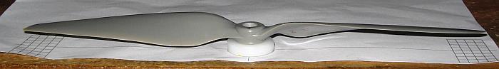 The
precision-machined hub, placed on a very flat surface (not on the old
workbench shown here!) is also used to measure the height of each tip
over the surface. To rule out any imprecision of my hub, this is also
done
by measuring twice, rotating the propeller a half turn between
measurements. Most propellers are crooked in this sense too, but
fortunately that's easy to correct by carefully sanding down the
propeller's seating surface, until both tips end up at identical
heights.
The
precision-machined hub, placed on a very flat surface (not on the old
workbench shown here!) is also used to measure the height of each tip
over the surface. To rule out any imprecision of my hub, this is also
done
by measuring twice, rotating the propeller a half turn between
measurements. Most propellers are crooked in this sense too, but
fortunately that's easy to correct by carefully sanding down the
propeller's seating surface, until both tips end up at identical
heights.
For this to work, it's necessary that the upper area of the propeller's
hub hole has some clearance around the motor shaft, so that its bottom
seating surface determines its alignment. The lower part of
the hole instead must be a snug fit to the motor shaft, for precise
centering. For this purpose propellers usually come with a kit of
slightly conical adapter rings, made from soft plastic. Some propellers
don't have these, and sit loosely on the shaft, with some play. These
should not be used! The HJ carbon fiber props are like that. Of my 4
units, one fit reasonably snugly, two are loose, and one fits
so tightly that it's hard to install and even harder to get off!
Getting both propeller tips to pass at exactly the same height is
absolutely essential to have any hope of decent dynamic balance! Tip
height should always be final-checked after the propeller is
mounted on its motor. And if it's removed and reinstalled, it has to be
checked again. And after each serious ground contact or other traumatic
experience it may suffer, it also needs to be checked again!
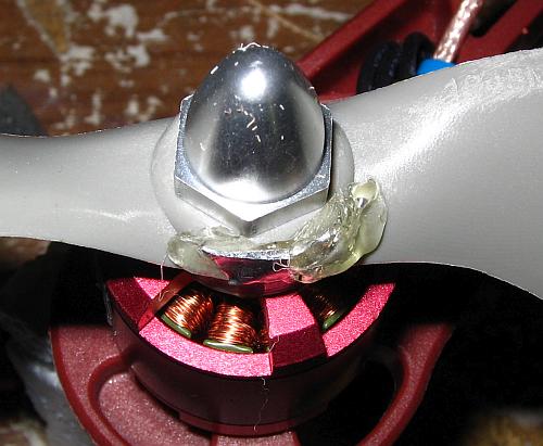 After
picking the straightest propellers, and sanding down their
mounting surfaces to level the tips, I used my balancers to do at
least static balancing. To cancel the mass imbalance caused by
the
crooking, a lot of weight needs to be added to one side of the
propeller hub. I used thick solder splashes (tin/lead alloy, quite
dense and soft), cut empirically to the required size,
installing
them with hot glue. These weights need to be attached near the top of
the hub, because the hub of these props is lower in average than the blades, so that
attaching weights at mid height of the hub or lower will improve static balance
only, while worsening the dynamic balance!
After
picking the straightest propellers, and sanding down their
mounting surfaces to level the tips, I used my balancers to do at
least static balancing. To cancel the mass imbalance caused by
the
crooking, a lot of weight needs to be added to one side of the
propeller hub. I used thick solder splashes (tin/lead alloy, quite
dense and soft), cut empirically to the required size,
installing
them with hot glue. These weights need to be attached near the top of
the hub, because the hub of these props is lower in average than the blades, so that
attaching weights at mid height of the hub or lower will improve static balance
only, while worsening the dynamic balance!
Then I fine-tuned the transverse balance by adding some more hot glue
where needed. If there was any significant longitudinal imbalance, I
sprayed fast-drying lacquer onto the underside of the lighter blade
tip, let
it dry, then measured again.
After balancing each prop, I mounted it on its motor, checked the tip
heights, then test-ran the motor, measuring vibrations over the whole
speed range. If still high,
I rotated the prop a little, and repeated this, until getting the
lowest possible vibrations.
Since the prop nuts have very loosely fitting threads, they end up in a
different position each time I install them. So sometimes all it takes
to improve or destroy the balance is to loosen and re-tighten
the nut!
It would be best to dynamically balance the complete assembled
motor+propeller+nut combination, and then never touch it again. But I
haven't
come up yet with a method to do this comfortably. If you have a
suggestion, let me
know. At this time the only thing I can do is adding two little weights
(tape) at different places of the motor runners, one at top and one at
the bottom, and measuring the vibration each time, trying to optimize
the size and the angular location of each weight, step by step. That's
a slow procedure. If there is a significant dynamic imbalance in the
prop, it takes a relative large amount of weight at both places of
the motor runner to compensate this.
And even perfect dynamic balance would leave some aerodynamic imbalance caused by
the crooked propellers! I don't know how much effect that has. Clearly
it
would be best to have really straight, precise propellers. One can
dream, right?
In any case, after all this effort the Ugly Bird experienced a great
improvement in its Parkinson disease. There was far less jello effect,
almost none when using the soft foam camera mounting, and the PID
autotuning also worked flawlessly! It hadn't worked before simply
because of excessive vibration, even while the vibration reported
by the Arducopter software was well within the range considered
acceptable. I suspect that the vibration reported by the
software in the log files is only the components falling below the digital filter's
cutoff frequency. The vibration at propeller rotation frequencies is
well above that cutoff, but apparently still has a large impact on
proper operation of the autotuning procedure.
After correct autotuning to optimal PID parameters, the Ugly Bird
became a snappy responder, and very obedient to any orders
from
its elders, just like it fits properly brought-up young people and
drones!
On the ground
The copter is only part of the story. The part that flies. The other
part stays on the ground, but is important too.
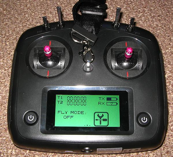 First,
we have the RC transmitter. It has 10 channels, touch screen,
is
fully programmable, and has a simplistic, aesthetically pleasing look
which appeals
to me much more than the more usual RC transmitters that look like
taken out of an old arcade game or sci-fi movie. But of course it's black... and gets almost
glowing hot in the sun for that reason!
First,
we have the RC transmitter. It has 10 channels, touch screen,
is
fully programmable, and has a simplistic, aesthetically pleasing look
which appeals
to me much more than the more usual RC transmitters that look like
taken out of an old arcade game or sci-fi movie. But of course it's black... and gets almost
glowing hot in the sun for that reason!
It has the usual two gimbal sticks, which are fully self-centering,
although the throttle function can be changed to non-centering if so
desired. I have noticed that in the Arducopter community many people
prefer a non-centering throttle stick. But my flying style, and I
suppose that most other multicopter flier's too, involves almost permanent use
of fully stabilized, highly automatic flight modes, in which this stick
does not control any throttle nor power, but instead controls vertical
displacement, just as the right stick controls horizontal displacement.
So it makes a lot of sense to me to have the self-centering function,
and so I left it like it came.
The sticks don't have front-panel trim adjustments. Drones do not use
such trimming, since the drone proper is trimmed rather than the
transmitter. But if anybody wants to use this radio for other
applications, trim can be set both via the touch screen and via
rear-side buttons.
The two power buttons need to be pressed together. This prevents
accidental activation. Also the transmitter refuses to be be switched
off while the drone is still on. So it's not possible to accidentally
switch off the transmitter while flying. If any special weird
situation
requires switching off the transmitter while the receiver still is on,
this can be done by popping open the battery door and briefly
disconnecting one of the batteries.
Of the four switches on top, two have 2 positions each, while the other
two have 3 positions each.
Not visible in this photo are two thumbwheel potentiometers,
located on each side. These are also self-centering.
Any switch or potentiometer can be assigned to any channel. Channels
can be inverted, exponential curves can be programmed for individual
channels, it's possible to link and mix channels, and so on.
My current setup, as I write this, is the following: The two sticks of
course control the basic four functions of a quadcopter: Up/down,
front/rear displacement, left/right displacement, left/right yawing.
The right 3 position switch controls the flight modes: "Loiter" in the
default position, "altitude hold" in the middle one, and "stabilized"
in the last position. The first and last of these names are highly
misleading, but are the lingo used in the Arducopter world. "Stabilized" is
actually the least stabilized of all modes the software provides! It
means that the autopilot does just basic inertial stabilization, while
everything else is left to the human pilot. It's the mode least
dependent on proper functioning of all sensors aboard the drone, and
most dependent on the operator. For this reason it's considered an
emergency fallback mode for when things go wrong, and it was strongly
suggested to me to always have this mode available. But in normal
flying practice I don't use it. Only for very basic testing. I think one would
need to have masochist inclinations to fly a long time in stabilized
mode...
In altitude hold mode the autopilot controls the motor power, so the
operator only needs to control the vertical displacement and the 3D attitude. In this mode the
drone still only uses inertial navigation plus the barometer
(altimeter), while GPS vertical information is optional. So this is a
fallback mode for situations in which the GPS is acting up - but that
hasn't yet happened to me. The M8N GPS receiver works very
well,
using not just GPS satellites but also those of other constellations. I
do use this mode for testing, though, because it's good to be able to
switch off automatic position correction and let the Ugly Bird float
freely while doing certain tests.
In loiter mode all systems are active and engaged, the autopilot
controls all motions, holds altitude and position, and the operator
just inputs orders of where to go and where to point. Loiter mode
elevates the operator from the position of a helmsman to that of a
captain.
I set up the right side 2-position switch for automatic return to base.
If
anything bad happens, like me losing orientation, the FPV link failing,
a bird dropping something in my eyes, or the sun suddenly being turned
off, I can simply throw that switch, and the Ugly Bird will
return home on its own. I had to do this one time already, when I lost
the video link while flying behind a thick stand of trees. This
return-to-base function is fully configurable too, of course. I set up
mine with enough altitude to get over any obstacles in my area, to
autonomously land the drone, to allow me to fine-correct the automatic
approach,
and to allow me to interrupt automatic return and re-take control
whenever I want.
You may be starting to get an idea of how configurable the Ardupilot
software is!
Back to the radio: I set up the left 2-position switch to control the
grabber, and the left 3-position switch is my wildcard at this time: I
use it as emergency stop when I'm doing any dangerous testing, as
autotune invocation control when I need to autotune the PIDs after
any significant change to the drone, and else I simply use it to
activate the beeper, so I can
tell the Ugly Bird to scream for help in case it gets lost in the
forest, giving me a greater chance of finding and recovering it.
The left thumbwheel control is used to tilt the camera down and up, and
the right thumbwheel is only used like a pushbutton to switch
between various OSD overlay formats, including a blank one that allows
enjoying the FPV landscape without any data cluttering except warning
messages.
I don't use any channel to control the camera nor the video
transmitter. As soon as the drone is powered up, the transmitter starts
transmitting, and if there is an SD card in the camera, it starts
recording. The configuration of both units is done on the ground, via
their pushbuttons. When the drone battery is disconnected, the camera
closes the video
file.
During flight the display shows transmitter and receiver battery
status, and there are two timers which can be used as needed. I often
use one as flight timer, to make sure I land before running out of
juice, in case the FPV stops working and thus I lose the telemetry.
Unfortunately the back link from the RC receiver isn't used to send
down
signal strength information, nor anything else relevant. It's only used
to send the receiver supply voltage data, and that always stays
constant in my setup, being a regulated voltage. This lack of RSSI is
my
main complaint about this radio.
The whole thing is very practical and ergonomic. I like it a lot. It's
an excellent radio, specially for the price! My only little complaint
regarding ergonomics is that the carrying strap is attached in the
middle of the front panel, and that makes the radio dangle around
rather uncomfortably in a roughly horizontal orientation when hanging
from this strap, and also the strap
tends to get in the way of the display. I would prefer a strap
attachment at the top, intended just to carry the radio around. During
flight I hold the radio in my hands anyway. The controls are all well
placed, and the transmitter is easy and comfortable to use.
I should add that so far I haven't had any RC link dropouts, or at
least none that I would have noticed, despite flying at significant
distances and hidden behind dense rain forest.
Another plus point is that
the 4 AA batteries last very long. I use rechargeables, and since I got
the radio I had to charge them just two times. With only about 6 hours of actual flight time, but many hours
of use in the workshop during setup and testing.
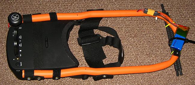 The
goggles instead are a completely different story. As much as I like the
FlySky radio, I dislike these Eachine goggles! The ugly PVC conduit
support-and-balancing structure I had to build already illustrates one
of their big problems: Horrible ergonomics, totally unbalanced, a real
torture to use as they come! Almost all of the weight of these goggles
is in the very front, and they come with a strap that supports them
from the rear and from the top near the rear. So the strap has to be tightened very much in order to
keep the goggles from dropping off your face, and then they exert a
heavy force on your face and nose. In addition the stressed strap tends
to slide up over the back of the head, and again the goggles fall off
your
face. If you ask me, that's totally unusable and unacceptable, except
if you enjoy wearing the goggles while angling your neck forward and pointing
your face straight down at the ground. In that position, with the
goggles hanging freely from their strap under your face, they don't
hurt and
don't fall off. But that's an uncomfortable position.
The
goggles instead are a completely different story. As much as I like the
FlySky radio, I dislike these Eachine goggles! The ugly PVC conduit
support-and-balancing structure I had to build already illustrates one
of their big problems: Horrible ergonomics, totally unbalanced, a real
torture to use as they come! Almost all of the weight of these goggles
is in the very front, and they come with a strap that supports them
from the rear and from the top near the rear. So the strap has to be tightened very much in order to
keep the goggles from dropping off your face, and then they exert a
heavy force on your face and nose. In addition the stressed strap tends
to slide up over the back of the head, and again the goggles fall off
your
face. If you ask me, that's totally unusable and unacceptable, except
if you enjoy wearing the goggles while angling your neck forward and pointing
your face straight down at the ground. In that position, with the
goggles hanging freely from their strap under your face, they don't
hurt and
don't fall off. But that's an uncomfortable position.
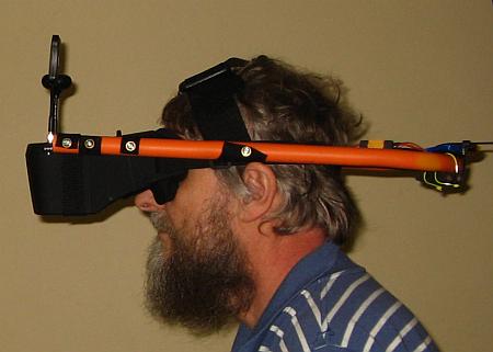 So
I crafted this funny/ugly frame, counterweighted by the battery and
two pieces of steel rebar coated in shrink wrap tubing. With this
contraption it's actually
possible to wear the goggles without torturing my face and nose, but,
well, it's still not really comfortable to wear, nor very practical to
carry around.
So
I crafted this funny/ugly frame, counterweighted by the battery and
two pieces of steel rebar coated in shrink wrap tubing. With this
contraption it's actually
possible to wear the goggles without torturing my face and nose, but,
well, it's still not really comfortable to wear, nor very practical to
carry around.
And I guess I had better not going to any beauty contest while wearing
this thing. But since I won't win any beauty contest even while not wearing this
thing, it doesn't matter! ;-)
Now let me tell you the sad story of these goggles, step by step, from
the beginning:
I decided to buy this model because it was recommended on several
websites as the best low-budget FPV goggles, and compatible with
spectacle users. Its video recording feature is attractive, it
has diversity reception, it comes with decent antennas, it has a
built-in
battery - all these features set it apart against much more expensive
units.
When the goggles arrived, my first nasty surprise was that there was
absolutely no way to wear them over my glasses! My glasses are
140mm wide, and 41mm tall. Not big, really, but way to big to
fit
in
the 108×35mm opening of these goggles!
I checked the websites of spectacle frame manufacturers. Even frames
for children are bigger than what fits through the opening of
these
goggles!
Then came the second nasty surprise: Looking into the goggles while
pressing my glasses as much against the cushioning as I could, I
couldn't focus on the image. I'm at that glorious (???) age when people
need
three separate spectacles for far vision, reading, and in between.
None of
them allowed me to focus on the screen of these goggles.
The rear part of these goggles easily detaches from the front. The
rear
contains nothing else than a single Fresnel lens, while the front
contains all the electronics, the battery and the display. The
front part can be
used alone as a small monitor, and that worked well, I could see it
fine while wearing my reading glasses. Of course, with my reading glasses I can't see a drone in the sky... And with multifocal
glasses I can see neither. Such are the glories of old age. My recommendation to all kids out there: Stay young!
It quickly became clear that I needed to have special glasses made, to
be mounted inside the goggles. These had to be child-size, and
precisely positioned to give me enough field of view to cover the
screen. But what prescription do I need? Fortunately I own a test lens
set, so I could try out what short-distance addition I need, on top of
my normal prescription, to be able to focus on the goggles' screen. The
shocking result: 6.5 diopters!!!! The optical system of these
goggles (consisting of that single Fresnel lens) is so blatantly
misdesigned that the virtual image is placed just 15cm away from the
wearer's eyes! Children can usually focus that close without any
trouble. Young adults often still can, with some effort. But people
like me, already packing their suitcases to travel into Oldie Land,
definitely
cannot!
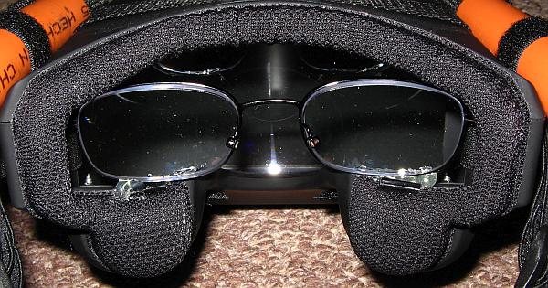 But
that's not all. The single Fresnel lens results in requiring an
unnatural convergence of the eyes. This is tiring too. I calculated how
much prism correction my special glasses would need to correct for
this, and it was so much that the optical company couldn't make it. The
lenses would have ended up too thick. So I finally made my prescription
for highly special oldie reading glasses with my normal distance
prescription
plus a 6.5 diopter addition, plus the highest possible prism
correction, and having a strategically calculated, very
narrow distance between optical centers (aka pupil distance),
which would add the missing convergence. I had these very special
glasses made in China, in a kid-size frame.
The workers at the optical company in China must have wondered
very hard what these strange glasses are for, but they did deliver
exactly what I wanted!
But
that's not all. The single Fresnel lens results in requiring an
unnatural convergence of the eyes. This is tiring too. I calculated how
much prism correction my special glasses would need to correct for
this, and it was so much that the optical company couldn't make it. The
lenses would have ended up too thick. So I finally made my prescription
for highly special oldie reading glasses with my normal distance
prescription
plus a 6.5 diopter addition, plus the highest possible prism
correction, and having a strategically calculated, very
narrow distance between optical centers (aka pupil distance),
which would add the missing convergence. I had these very special
glasses made in China, in a kid-size frame.
The workers at the optical company in China must have wondered
very hard what these strange glasses are for, but they did deliver
exactly what I wanted!
I removed the spectacle's legs and nose pads, installed what was left
inside my Eachine goggles in the exact right position, using some hot
glue, and voilá, now I could see the screen clearly and comfortably!
But anybody who doesn't have enough knowledge about optics
will have a hard
time trying to see sharply while using these goggles. Unless he
is young
and still has a very wide accommodation range.
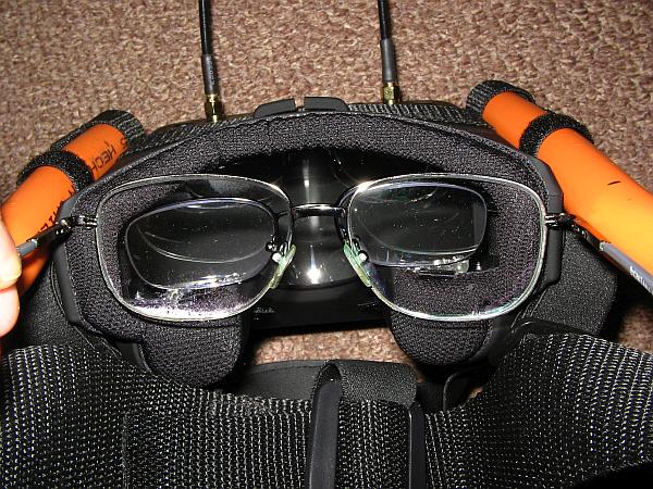 Here you can see my
normal spectacles placed in front of the goggles' opening, and you can
compare sizes.
Here you can see my
normal spectacles placed in front of the goggles' opening, and you can
compare sizes.
Note that even the child size spectacles wouldn't fit through the
opening! I had to remove their legs and diagonally coax
them through the opening. Once inside, they had enough
clearance
to move around a little, before I glued them in place.
If you think that very bad ergonomics and totally wrong optical design
was bad enough, then please hold your breath, because the electronics in
these goggles also have trouble! The worst of these is battery
management. These goggles continue drawing a small but significant
current when switched off. So the internal battery will discharge when
they are stored for more than about a month or so without being charged. Lithium
ion batteries normally come with a protection circuit, that will
disconnect the battery if overly discharged or overcharged, to avoid
battery damage. In the event that this disconnection fails to work, the battery protection circuit has a last resort: A
fuse that can be blown on purpose. The battery protection circuit will
blow the fuse, as a last ditch effort to avoid the risk of the battery
bursting into fire. The battery becomes dead and unusable when it does
that.
And that's exactly what happens in these goggles! The battery
protection circuit is misdesigned. When the battery is discharged too
deeply, the circuit opens the charging switch, not the discharging switch!
So the slow discharging continues, until the circuit blows the fuse. At
that point the battery is dead, to any normal user.
After I did all the initial tests with my goggles, and ordered the
correction glasses, I had to wait for three months for the glasses to
arrive from China. COVID-19 slowed down everything, there and specially here. And
when the glasses arrived, the battery of my goggles was as dead as a
doornail. It would not charge. At that point I took apart the front of
the goggles, and discovered the mess.
I'm not alone in this. There are many reports on the web from people
who saw the battery in their Eachine goggles die very soon, and some other
people actually got the goggles with an already dead battery in them!
I removed the battery, hacked it open, removed the protection circuit
with the blown
fuse in it, carefully charged the battery in my programmable charger,
tested it. It measured 1100mAh. The rating printed on it is 1400mAh.
Good enough, I guess... I installed an XT60 connector on it for
standardization, plus a balancing connector, and I'm using the battery
outside the goggles, tied to the rear of my fancy conduit frame. But
1100mAh is just too little. The runtime is barely enough for three
flights or so. While the goggles have an input for 12V, and come
with a cable to connect this to a 3S battery, I think that a better
solution is
installing a 2S battery of about 4000mAh capacity, connected to the
internal battery connection point. This would preserve
the functionality of the battery level indicator, which is useless if a
3S battery is used on the 12V input.
Not that the battery level indicator isn't very good! It shows just
three bars. All three bars on means a fully charged battery, but the
first bar goes out as soon as you start using the battery. The last one
goes out when the battery is still at roughly half charge. For the
entire second half of its discharge cycle, there is no indication. So you can use
these goggles for a considerable time after the battery indicator tells
you the battery is empty, but you don't know how much charge is left.
That's not good.
The receivers work quite well, and the antennas too. But I do get video
dropouts when the drone is straight overhead. This must be a hole in
the 3D directional pattern of the Foxeer antenna on the drone, because
it's quite independent of the receiving antennas' orientation.
The video recorder function works well as long as the received signal is
perfect. But as soon as there is any dropout, it stops recording, and
won't resume on its own! This is very bad. My main use of the recording function
is for safety. If the drone ever crashes in my jungle, it will be very
hard to find. It would be extremely useful to record the FPV video,
complete with GPS-derived location of the drone, until the last moment!
But if the video recorder shuts itself down every time there is a brief
dropout, the chances are high that in the event of such a crash I won't have the needed location data on the SD card!
This is aggravated by the fact that the 5.8GHz doesn't get through
foliage very well. Even a relatively thin stand of trees will block the
signal - and I have thick forest! That's not a fault of the goggles, of
course, being a characteristic of those microwave frequencies, but it's one more reason to look for a different FPV system,
one that works on a much lower frequency.
In the last two days before writing this, my goggles started
developing additional problems: Sometimes they become
unresponsive
to the buttons. ALL buttons, even the power button. Reception
continues, but I can't start the video recording, nor can I switch the
goggles off. Reset by unplugging the battery is the only workaround.
And then, during a nice flight yesterday, suddenly the goggles turned
itself off. I tried to turn them back on. No reaction. So off my face
they
went. On went my long-distance glasses. The drone was in sight, so I
landed it visually, without needing to use the automatic return feature.
After landing, and checking the goggles, they turned on and worked
normally. Are they overheating, perhaps? They do get quite hot. The
battery was
still 70% charged, so it can hardly have been the cause of the turn-off.
To say that I'm dissatisfied with these goggles would be the
understatement of the year. They were the most expensive part of my
whole setup - and they turned out to be the worst!
Firmware updating, and configuration
The Ugly Bird has 12 microcontrollers onboard, unless I'm missing a
few. The radio, goggles, and the battery charger have their own. All of
them run some firmware, and most of it is upgradeable and
configurable by the user. This is an enormous playground, and has kept
me busy and entertained throughout the COVID-19 lockdowns!
The biggest, most important thing here is the Pixhawk flight
controller, which runs Arducopter firmware, one branch of Ardupilot.
The Pixhawk can also be used with other firmware, and Arducopter can
run on many different controllers, but the combination of Arducopter on the
Pixhawk seems to be the most common and best supported one.
My Pixhawk clone came with Arducopter pre-installed. The
version
that came in it was 3.6.8. By the time I got it, version 3.6.11 or so
was the current one, and before long the hardcore users had all
upgraded to the freshly released 4.0.0 version, and then the following
bugfix releases. At the time I write this, 4.0.5 is current.
When I asked for help on the Arducopter
forum about some issues and doubts, several people urged me to upgrade. I really had intended to try
the pre-installed version first. Specially when I saw that some drones
were crashing due to bugs introduced in the new versions. Being new to
drones, I prefer using an older, well tested version, rather than
acting as beta tester of new releases. Anyway I tried to follow the
suggestions and upgrade, but I couldn't. The problem is
that Ardupilot upgrading and configuration is done from a PC
program called Mission Planner, this program works in Windows 7 or
higher, but I still use Windows XP (yes, in 2020! Call me old
fashioned. Compatibility requirements with old software and external
hardware prevent me from upgrading). So I run MissionPlanner in a
virtual machine that has Windows 7 Ultimate in it, and it runs, although
slowly... Good enough to set up the parameters, but not good enough to
update the firmware. I tried several times, and it always failed. So
I'm stuck to Arducopter 3.6.8, at least for now, and I'm not unhappy
about that, because this version is working well for me, and
has
all the features I need.
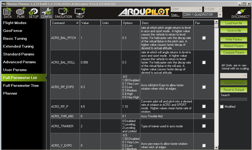 Mission
Planner has many functions, ranging from firmware loading
and configuration of the flight controller, all the way to what
its name
suggests, planning fully automated missions.
Mission
Planner has many functions, ranging from firmware loading
and configuration of the flight controller, all the way to what
its name
suggests, planning fully automated missions.
Here is one of the windows that I use a lot, and which is also one of
its most basic ones. It gives access to all parameters of the flight
software, in alphabetical order, allowing the user to change
them, send them to the Pixhawk, read out parameters, compare them to
older or newer ones, and so on. Here it's showing just the first few of
a very long list.
Many of these parameters can also be changed through higher level
windows, but this very basic window gives direct access to all of them,
which I often find to be the quickest way to make a configuration
change.
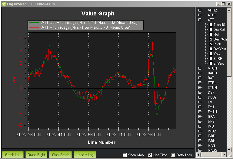 This
screenshot shows another very powerful and useful feature of Mission
Planner: Its flight log browser. It accesses the drone's "black box",
and allows to see and plot any parameters recorded there.
This
screenshot shows another very powerful and useful feature of Mission
Planner: Its flight log browser. It accesses the drone's "black box",
and allows to see and plot any parameters recorded there.
In this example I made it show the desired pitch angle, in green, along
with the actual pitch angle, in red. One can immediately seen that the
flight software's attitude control module was basically putting the
drone in whatever pitch angle was requested, but with quite a lot of
spikes and noise, and one large deviation near the end of this time frame. This means that the drone
was shaking with
a magnitude of roughly half a degree, probably caused by turbulence, and
when one sees such behavior one can try improving the PID gain
settings to try getting the drone to more precisely correct the angle,
and then check the flight data from a new test flight and see if the
actual angle now more closely follows the desired one.
Many parameters can be plotted like this, and the firmware is configurable to select which parameters are recorded.
And of course, should the drone go out of control and crash, analysis
of the flight data is extremely useful to see what went wrong, and fix
it!
I could write a web page at least as long as this one about all the
many configuration details of Arducopter. Each drone is special.
Probably no two drones use the same configuration. Maybe some day I
will write a page about it. But Arducopter is really well documented,
so if you are interested, better go straight to the Arducopter
documentation and read up there!
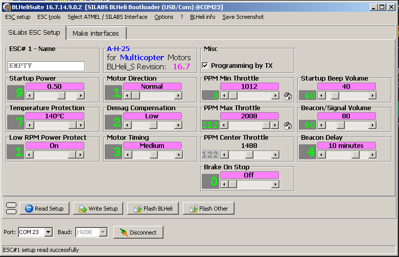 The
ESCs can be configured through a program called BLHeli Suite. The
version I have is 16.7.14.9.0.2, and it works fine on Windows XP. The
ESCs are connected to the PC through an USB to serial adapter, one at a
time. I used the software o check their setup, but it was fine for
copter use. I didn't have to change anything. Nor did I need to upgrade
the firmware.
The
ESCs can be configured through a program called BLHeli Suite. The
version I have is 16.7.14.9.0.2, and it works fine on Windows XP. The
ESCs are connected to the PC through an USB to serial adapter, one at a
time. I used the software o check their setup, but it was fine for
copter use. I didn't have to change anything. Nor did I need to upgrade
the firmware.
ESCs can usually also be configured through the flight controller,
which is more convenient, but I didn't see any reason to try getting
that to work, because I don't foresee having to make frequent changes
to the ESCs' setup.
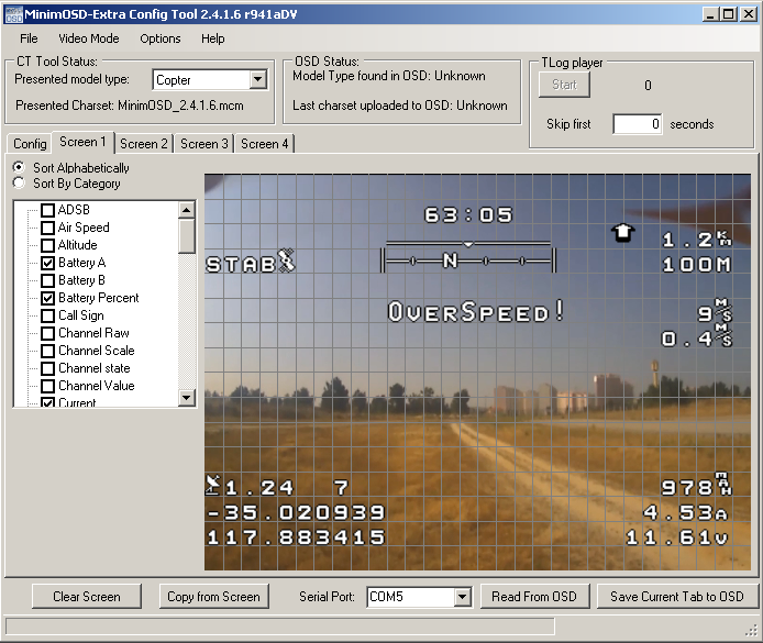 My MinimOSD
came preloaded with a very old version of the firmware, that has rather
limited functionality. I connected it to the PC using the same adapter
I used for the ESCs, using the MinimOSD-Extra Config Tool, which runs
fine on Windows XP, and I loaded the newest character set and the
newest firmware that comes with this program.
My MinimOSD
came preloaded with a very old version of the firmware, that has rather
limited functionality. I connected it to the PC using the same adapter
I used for the ESCs, using the MinimOSD-Extra Config Tool, which runs
fine on Windows XP, and I loaded the newest character set and the
newest firmware that comes with this program.
Then I configured the OSD to show exactly what I want, where I want it.
This screenshot shows the main screen I set up. I also set up a far
more complete "engineering" screen, and a blank screen (except for
emergency warnings). In flight they can be selected by means of the
right thumbwheel on my RC transmitter.
By the way, that landscape and those coordinates aren't mine! They come with
the program...
I slimmed down this layout as much as possible, removing function
designators and other stuff that I don't need, and which would clutter
up the screen too much.
In both top corners I had to leave some empty space, because the
goggles and the camera put some information of their own in those areas!
So finally I get the goggles' channel info and the flight mode in the
top left corner, the camera's recording status, ground distance and
direction, and altitude above takeoff in the right top corner,
horizontal speed and climb rate below that, used battery capacity,
battery current and battery voltage in the lower right corner, GPS
GDOP, number of sats, latitude and longitude in the lower left corner,
and flight time, heading and any warning messages in the middle of the
sky.
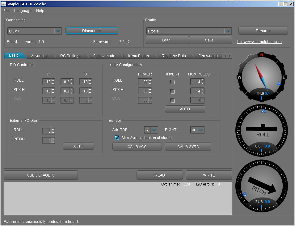 The
gimbal controller connects to the PC by USB, and the program
interfacing with it is this. It must be exactly this version, no older
and no newer one. The firmware loaded in the gimbal controller must
match the PC program version.
The
gimbal controller connects to the PC by USB, and the program
interfacing with it is this. It must be exactly this version, no older
and no newer one. The firmware loaded in the gimbal controller must
match the PC program version.
The firmware of the gimbal controller must not be upgraded! These
inexpensive controllers sold in China are approximate clones of the
original one, with differences, and they use a specially modified
firmware version. There are reports on the web about people trying to
load a newer firmware version, finding that the board doesn't work with
it, and then having serious trouble while trying to reinstall the
correct
version.
The gimbal needs manual PID tuning to work well. This screenshot shows
the values I used after brief experimentation, which work pretty well,
but I must warn my dear readers
from blindly copying my PID values, which would certainly be
wrong for their gimbals, given that the gimbal I built is a
one-of-a-kind item, much smaller and lighter than most, and using
motors few people seem to use.
At the time of writing this I have only done pretty basic setup of the
gimbal. For example I don't yet feed the flight controller's attitude
data to the gimbal, which could easily be done and might improve
stabilization. It's pretty good without that, though, so I'm taking
things one step at a time!
Enough documentation comes with the software to explain how to set up
and tune the gimbal. There are also videos on Youtube about this matter.
By the way, BGC means "brushless gimbal controller". Old gimbals used
brushed motors, but modern ones all use brushless ones.
The Runcam camera's firmware can be upgraded by putting the update file
on an SD card, and the camera will do the rest. I already upgraded it
to the latest version, but there are still some features missing.
Specially I miss the very basic feature of manual white balancing. The
camera comes without that, white balancing is always automatic, and
results in severe colors shifts according to what
the camera is looking at. Basic color response is also somewhat poor, for example bright red flowers are rendered in
an indistinct muddy brownish/reddish tone.
I havn't had any need to upgrade the GPS receiver's firmware. I
understand that this can be done too! The RC system can also be
upgraded, both the receiver and the transmitter, but this hasn't been
necessary.
So, how does it work?
The Ugly Bird flies pretty well! Until writing this I have done about 6
flight hours, with no crashes, no fly-aways, no scares, no strange
things happening. It can climb like a rocket, sink like a rock, race
like an albatross, battle the wind like a petrel, and it remains stable
through all this. So I'm quite happy with the performance of
the
basic platform's technical equipment, that is, flight controller,
remote control, ESCs, motors, GPS, battery. The frame is too heavy and
too wobbly, so I hope to eventually rebuild the drone on a better
frame. In fact I intend to shave away as much weight as I can, not just
by building an optimized, very lightweight frame, but also by
eliminating all those individual plastic boxes, eliminating any
unnecessary stuff like the pushbutton, and maybe even going to extremes
such as using very thin enameled wire, eliminating connectors,
replacing cable ties by yarn wrappings... In its current
incarnation the Ugly Birds weighs 1345g, complete ready to fly, which
is considered still in the normal range for a quadcopter of this size and
power, but rather on the high side. It consumes approximately 16A while flying, which results in a
theoretical absolute maximum flight time of slightly less than 19
minutes, but to stay safe and don't torture the battery too much I
normally keep my flight time to 10 minutes, occasionally 12 minutes, at
most about 14 minutes. It should be possible to lean down the Ugly Bird
by at least 300g, applying the measures mentioned above. Since a lower
load increases the efficiency of the propellers, and a lower discharge
current allows getting closer to the battery's discharge limit without
damaging it, the gain in flight time should be significantly greater
than just a proportional amount. I would expect a maximum theoretical
flight time of at least 28 minutes after that weight reduction, with a
maximum safe and good flight time in the range of 15 to 20 minutes.
Also I intend to test more propeller types, in the hope of finding one
that is more efficient, and perhaps even better balanced than the ones
I have. I don't really dare to hope for propellers that are actually
straight... Larger propellers should always be more efficient, but
require enlarging the frame, increasing the weight, and they require
motors capable of higher torque, which are heavier too. It's likely
that I should keep to 10" propellers and optimize the system within
that limitation.
A long endurance quadcopter is basically a big battery with the
lightest possible frame, motors, and electronics strapped to it, using
the largest possible propellers. But large propellers are less good for
flying fast, which includes compensating for strong wind. So there are
always compromises to be made. At the current state of battery
technology it's probably best to not aim at much more than 20 minutes
flight time. A flying object that needs to stay up longer shouldn't be
a quadcopter but a fixed-wing aircraft, and with an internal
combustion engine it can fly much longer than with battery power.
Anyway my goals are some aerial filming and photography, raising antenna
lines into trees, learning and having fun, and these goals are
fully satisfied with the flight time I'm getting. Any further
improvement would be just for the fun of doing it.
The grabber works fine, and I don't see any reason to further improve
it. I used it to install all the antennas I need for now, and it's just
waiting for more use. But I might install it in an easily removable
way, to save its weight when I don't need it, which is most of the time.
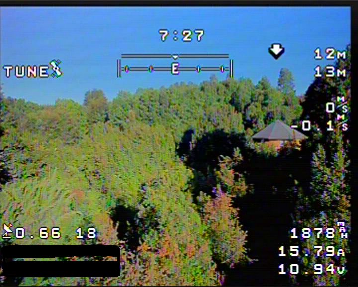 The
whole video system instead is another matter. I'm not happy with it.
Maybe I'm just expecting too much. This image shows the FPV video with
OSD recorded by the Eachine goggles. I blacked out the
latitude
and longitude for privacy. Also note that this
frame comes from video shot during a tuning flight, which makes it
special!
The
whole video system instead is another matter. I'm not happy with it.
Maybe I'm just expecting too much. This image shows the FPV video with
OSD recorded by the Eachine goggles. I blacked out the
latitude
and longitude for privacy. Also note that this
frame comes from video shot during a tuning flight, which makes it
special!
What the goggles show on screen looks exactly the same, except that the
black border isn't visible, and that there is some additional OSD in the
top left corner generated by the goggles, and a red dot appearing in
the upper right corner when the camera is recording video aboard the
drone.
I set the FPV video to PAL, because it's supposed to have a higher
resolution than NTSC, 576 lines. But to my eyes, the actual resolution
of this image is far lower than that, probably half the claimed rate!
Note that the OSD information is pretty sharp, but the video isn't. So
this is a limitation of the Runcam FPV video output, not of the video
transmitter nor the goggles.
In this image, lit by a low sun not long before sunset, the
colors look
quite nice, but still fall far short of reality. Specially the red is
very poor! Those small trees in the mid low area are densely covered
with intensely, fiery red flowers, which stand out so much that they
really scream at the anyone watching them. But the Runcam sees them in
a very dull tone, making them look more like withered foliage
than like
bright red flowers. Clearly the color gamut of this camera is very
limited.
The video quality is good enough to see where I'm flying, to stay
oriented and to fly back home, and if I fly low enough I can even
tell a dog from a cow, but that's it. FPV isn't enjoyable to me at
this low video quality! Flying close to obstacles by FPV isn't
safe, because it would be easy to collide with a thin branch before
having any chance of seeing it. And wearing the goggles for too long
produces great eye fatigue, because the eyes are constantly trying to
focus on this image, which looks very large in the goggles, but is totally
blurry.
I would accept a significantly longer latency if in exchange I would
get much better image quality. Digital FPV systems do that, but there
are few, and they are more expensive than my entire drone project!
 The
1080p video recorded onboard the drone by the Runcam is of course much
better. Downsized to the resolution of the thumbnail at right,
it actually looks sharp! But it isn't, at 1080p. Click the
image
to get the full-size image, and watch it at full size (1920×1080
pixels). You will see that it falls far short of actually resolving the
individual pixels.
The
1080p video recorded onboard the drone by the Runcam is of course much
better. Downsized to the resolution of the thumbnail at right,
it actually looks sharp! But it isn't, at 1080p. Click the
image
to get the full-size image, and watch it at full size (1920×1080
pixels). You will see that it falls far short of actually resolving the
individual pixels.
This camera has a 2 megapixel sensor. A 1920×1080 image has a tad more
than 2 megapixels. That would be about right, maybe the sensor actually
has the 2,073,600 pixels needed. But the catch is that sensor pixels are
single-color pixels, while a true 1920×1080 image has 2,073,600 three
color pixels! So there is always a lot of interpolation going on in
this camera. Also digital cameras usually use optical lowpass filters
(blurrers, very simply said), to avoid Moiré effect when looking at
regular patterns such as fabrics, and these filters further reduce the
resolution. So for a digital camera to be able to produce true full-HD
images, fully resolving the 2,073,600 pixels, it would need a
sensor having roughly 8 to 12 megapixels, along with a lens
that
can resolve them. A 2MP sensor can never produce a high
quality
full-HD image.
Keep in mind that I'm using a Yumiki distortion-free lens on my Runcam.
That's why the horizon looks straight! When using the original Runcam
lens the resolution might be a tad better, barely noticeable, but there
is severe fisheye distortion, which makes the original lens
unacceptable to me. The Yumiki lens instead causes some vignetting in
the corners. It's not very obvious in this particular brightly-lit
image, but when the general light level is lower the corners tend
to black out first. The original lens instead has no visible
vignetting.
 Related
to this, the Runcam really loves to have a lot of light. In full
sunshine it produces the quality shown above. When it's darker,
the resolution gets much worse! Look at the picture at left, click on it
for full resolution, and compare. It's from the same flight, but
tilting the camera down to look at a shaded area. Either the camera's
software is softening the image to reduce sensor noise, or it's binning
pixels for the same purpose!
Related
to this, the Runcam really loves to have a lot of light. In full
sunshine it produces the quality shown above. When it's darker,
the resolution gets much worse! Look at the picture at left, click on it
for full resolution, and compare. It's from the same flight, but
tilting the camera down to look at a shaded area. Either the camera's
software is softening the image to reduce sensor noise, or it's binning
pixels for the same purpose!
Note that the fiery red flower-covered trees look as subdued and dull
in the HD images as they look in the analog video link, showing that
this is a problem of the sensor or processing, rather than of
conversion to low resolution analog video.
I would love to show you some actual video of a flight. But these
videos are enormous! A 10 minute flight will produce a 3GB file, and
that's at a lower frame rate than the 60 fps the camera can nominally
produce! I have tried various video compressors, but the results
I get are poor. The compressors tend to reduce the image quality much more than the file
size! I don't understand what's going on, but these drone videos have a
very much worse ratio between image quality and file size than all
other videos I have ever seen!
Speaking about frame rate: This Runcam is rated to generate 60 fps
video. And yes, indeed it does record 60 frames per second, when set
so. But these aren't 60 new
frames per second! Even with fast-moving video, it repeats frames, so that the actual frame rate, counting only
newly generated ones, is lower. This is probably due to internal video
compression, done in part by dropping frames. Even during fast pans
often many frames are dropped. Still the video looks smooth enough,
so this is no problem, but this frame dropping raises questions whether
it makes any sense to look for cameras that are claimed to work at high
frame rates.
Also the frame rate selected should relate properly to the analog video
format selected for FPV. Since PAL runs at 25 fps, I selected 50 fps
for my HD video, rather than 60. It seems to work better.
The Runcam uses automatic white balancing, constantly changing the
colors according to what the camera is looking at. The automatic white
balancing cannot be turned off! When taking individual photos the
colors can be corrected later, but for video this is a very serious
shortcoming, because the colors constantly change! And it
would
be so easy to let the user turn off automatic white balancing, and let
him select sunny daylight, cloudy, and a few other such presets. I
actually wrote to Runcam about this issue, but apparently they didn't
even understand what I mean, asking me to provide videos to show the
"fault" of the camera. It was clear that they were thinking that I was
complaining about a manufacturing defect, and they didn't understand
that I was simply suggesting to allow the selection of manual
white balance in the menu... Since I cannot send a huge video through
my remote wireless internet connection, and got the feeling
that
the people at Runcam weren't understanding me at all, I let the issue
rest.
One time the camera turned itself off in mid flight. I don't know if
this was due to a bug in its software, a power supply spike, or what.
All power connections to the camera are soldered, except for the XT60
battery connector which is very safe, so there is no chance for lose
connections. And it can hardly have been due to overheating, because in
the Ugly Bird the camera is exposed to a lot of turbulent propeller
wind!
In any case it's noteworthy what this tiny, lightweight,
under-70-dollar camera can do, but on the other hand the camera built into my cheap
clamshell dumbphone from 15 years ago produced images that were no worse.
Coming from the world of high quality photography, using real cameras
with very much larger sensors and high quality lenses, I feel rather
limited with the Ugly Bird's video setup. It's definitely not
good
enough to shoot real full-HD video for publication, nor to shoot any
fine art photos. I will probably be looking for a much better camera
and digital FPV when I hopefully some day re-incarnate the Ugly Bird as
a Phoenix, in a new carbon fiber body.
Back to the homo ludens
aeromodellisticus
page.