Atwater Kent 206-X
 Once upon a time,
I think it was in 2002, my friend and colleague Alain Maury told me that
in the storage room of the house he was renting he had found an old radio.
He knew that I restored and collected radios, so he asked me if I would
be interested in yet another one. He also asked the house owner if the
radio had any future prospects, and got permission to dispose of it. When
I went to pick it up, the surprise was on my side: I had expected "any"
old radio, but finding an Atwater Kent cathedral from 1934 was certainly
beyond my expectations! This is the first Atwater Kent in my collection,
and I had been wanting one for years!
Once upon a time,
I think it was in 2002, my friend and colleague Alain Maury told me that
in the storage room of the house he was renting he had found an old radio.
He knew that I restored and collected radios, so he asked me if I would
be interested in yet another one. He also asked the house owner if the
radio had any future prospects, and got permission to dispose of it. When
I went to pick it up, the surprise was on my side: I had expected "any"
old radio, but finding an Atwater Kent cathedral from 1934 was certainly
beyond my expectations! This is the first Atwater Kent in my collection,
and I had been wanting one for years!
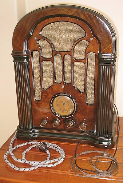
The radio was in somewhat poor condition - little finish remaining,
obvious signs of having been scraped with a sharp object during an earlier
refinishing attempt, the veneer delaminating but almost complete, all knobs
missing, and the electronics had been drastically modified. Still, it looked
very restorable, but would take some work. I brought it home and decided
to give it the very best treatment I could.
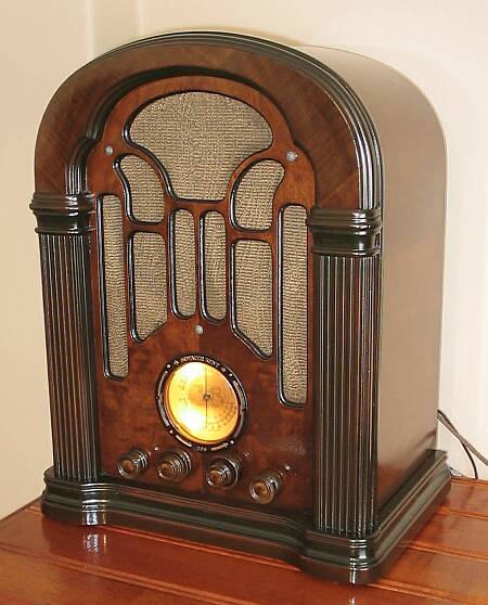
Just in case you are wondering: Of course, this photo shows the
radio after restoration!
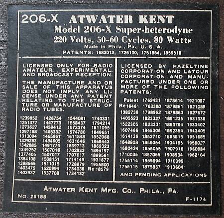 This is the type
label attached to the inside of the cabinet. The "X" stands for "export"
version. The radio was made specifically for countries with 220V mains
distribution. There was also a 206 model without any letter, which was
the same radio but with the transformer primary wound for 110V. And there
was also a quite different version, the 206-D, which was for 110V DC. Instead
of a rectifier tube, that one had a second output tube, necessary to achieve
enough output power at the low supply voltage of 110V.
This is the type
label attached to the inside of the cabinet. The "X" stands for "export"
version. The radio was made specifically for countries with 220V mains
distribution. There was also a 206 model without any letter, which was
the same radio but with the transformer primary wound for 110V. And there
was also a quite different version, the 206-D, which was for 110V DC. Instead
of a rectifier tube, that one had a second output tube, necessary to achieve
enough output power at the low supply voltage of 110V.
This radio is a superheterodyne using 2.5 Volt tubes. There is a 58
tube used as RF preamplifier, a 2A7 converter, a 58 IF amplifier, a 2A6
detector and audio preamplifier, a 2A5 power amplifier, and a type 80 rectifier.
A transformer delivers 5V at 2A for the filament of the rectifier, 2.5V
at about 6A for the filaments of the other tubes and the dial lamps, and
a high voltage for the plate supply. But my specimen was lacking this transformer!
There were just the mounting holes, and black marks where the transformer
had burned. Whoever repaired this set when the transformer failed, chose
to modify the radio for transformerless operation. None of the original
tubes were there. Instead, the tubes were 6D6 - 6A7 - 6D6 - 75 - 43 - 25Z5,
with the filaments in series, fed from 220V through a dropping resistor
that dissipated close to 50 Watt, and the chassis live at line voltage!
I decided to restore this radio to its original circuit, if I managed
to get the tubes. Fellow collector Renato Menare supported me in this decision,
and he was the one who provided most of the tubes, and many other parts
too! My own collection could provide only two of the six tubes I needed.
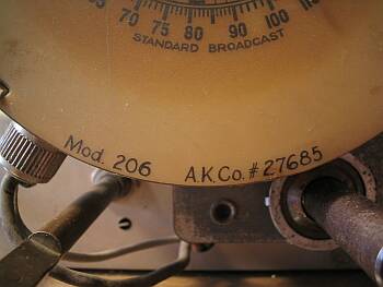 This radio is full
of numbers. The label is 28188. I guess that's what counts as serial
number for the whole radio. The dial has its part number
carefully hand-written on the otherwise type-set dial. There
are part numbers on the speaker, the cabinet, the chassis, and many
of the components.
This radio is full
of numbers. The label is 28188. I guess that's what counts as serial
number for the whole radio. The dial has its part number
carefully hand-written on the otherwise type-set dial. There
are part numbers on the speaker, the cabinet, the chassis, and many
of the components.
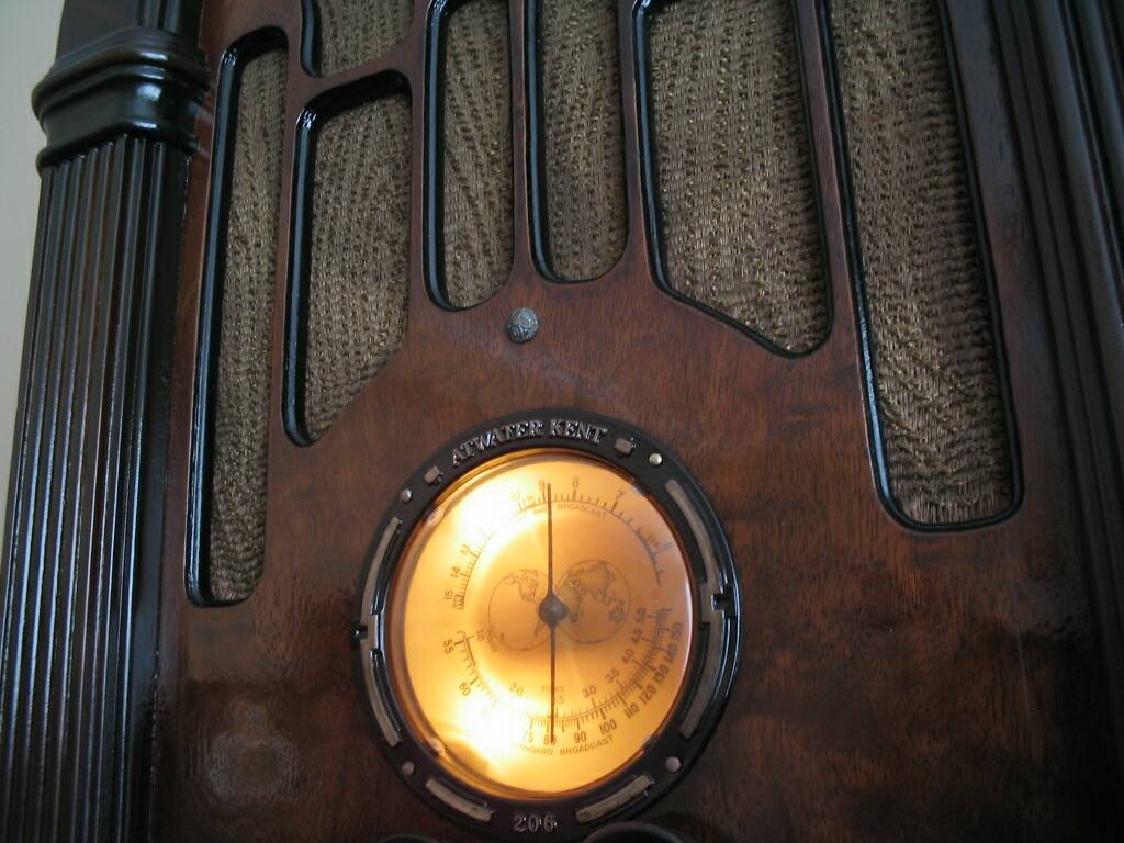
The 206 covers three bands. The standard broadcast band, and a short
wave band spanning 5.9 to 15.5 MHz, are the main bands, and the circuit
provides adjustments to achieve good performance and dial calibration on
them. The range between the two, 1.6 to 5.9 MHz, is provided as a third
band, but without adjustments and thus with lower performance.
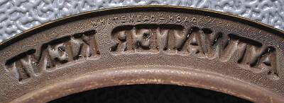 The
famous Atwater Kent quality shows in every detail. This is a picture of
the backside of the stamped brass dial escutcheon. Not only are the brand
name, model number and decorative figures formed in great precision, but
also there is a texture stamped into the metal. Looking very closely, I
discovered a very tiny, but crisp and precise "WHITEHEAD - HOAG" there.
Was that a contractor stamping these pieces, or what? Any info is welcome.
The
famous Atwater Kent quality shows in every detail. This is a picture of
the backside of the stamped brass dial escutcheon. Not only are the brand
name, model number and decorative figures formed in great precision, but
also there is a texture stamped into the metal. Looking very closely, I
discovered a very tiny, but crisp and precise "WHITEHEAD - HOAG" there.
Was that a contractor stamping these pieces, or what? Any info is welcome.
UPDATE! Pete Olin wrote with the following piece of information: W&H
was a major stamper of small metal parts, especially campaign buttons back
to the 1890's. So, Atwater Kent indeed outsourced the stamping of these dials, contrary to the urban myth that this brand build every part in house!
The texture appears on both sides of the metal. But the small text is
only on the backside, without any traces on the front. They must have used
enormous pressure to stamp the metal in this way!
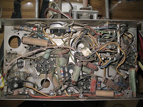 When I had
the tubes, I was ready to proceed and turn the radio back to its original
circuit. This picture shows the underside of the chassis after I removed
the non-original parts and wiring used for the modification. I did not
remove the phono connector. It is non-original too, and was riveted to
the chassis but never connected! The lugs show no signs of solder. I chose
to leave it in place because a non-original phono connector looks better
than a non-original empty hole in the chassis!
When I had
the tubes, I was ready to proceed and turn the radio back to its original
circuit. This picture shows the underside of the chassis after I removed
the non-original parts and wiring used for the modification. I did not
remove the phono connector. It is non-original too, and was riveted to
the chassis but never connected! The lugs show no signs of solder. I chose
to leave it in place because a non-original phono connector looks better
than a non-original empty hole in the chassis!
From this point, I moved slowly and went over the circuit from the antenna
input to the output and power supply, component by component, wire by wire.
Every part was checked to make sure it was in acceptable condition, and
correctly wired. Several bad parts were found, mostly leaky paper
capacitors and severely value-shifted resistors. Some resistors had grown
up to 500% in their resistance, and one of them was open. Of course, all
electrolytic capacitors were dry, including a non-original one fitted probably
in the 1960s.
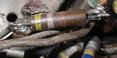 This
poorly soldered resistor is non-original too. It's 470 Ohm, while the original
was 20000 Ohm. You wonder why the technician who replaced this resistor
missed the correct value by so much? Well, Atwater Kent had its own, private,
and quite fancy color code for resistors! Nobody who didn't have access
to AK literature had a chance to decode their values! For example, the
blue-yellow-gray resistor down in the photo is nominally 165 Ohm. The order
of the colors didn't matter, in the manual this resistor is listed as "blue-gray-yellow"!
A blue-red resistor would be 100 kiloohm, one with a single black band
is 65 kiloohm, a single gray band means 30 kiloohm, and one with no colors
at all is 40 kiloohm! The 50 kiloohm value is black-yellow-red. Purple
alone is 6000 Ohm, but purple with yellow is 12500 Ohm. If you see any
logic in this, do tell me, please! :-)
This
poorly soldered resistor is non-original too. It's 470 Ohm, while the original
was 20000 Ohm. You wonder why the technician who replaced this resistor
missed the correct value by so much? Well, Atwater Kent had its own, private,
and quite fancy color code for resistors! Nobody who didn't have access
to AK literature had a chance to decode their values! For example, the
blue-yellow-gray resistor down in the photo is nominally 165 Ohm. The order
of the colors didn't matter, in the manual this resistor is listed as "blue-gray-yellow"!
A blue-red resistor would be 100 kiloohm, one with a single black band
is 65 kiloohm, a single gray band means 30 kiloohm, and one with no colors
at all is 40 kiloohm! The 50 kiloohm value is black-yellow-red. Purple
alone is 6000 Ohm, but purple with yellow is 12500 Ohm. If you see any
logic in this, do tell me, please! :-)
The funny thing is that the standard color code was in ample use by
1934. Only that AK chose to roll their own instead!
Atwater Kent capacitors are marked in code numbers. The first number
is voltage: 1 for 100V, 2 for 200V, and so on. The other two numbers give
the capacitance, increasing with larger numbers. So, if we know that a
capacitor marked 104 is 0.3µF, 100V, what would you expect a 204
to be? Logic would say, 0.3µF at 200V, right? Wrong!
It's 0.015µF! It's Atwater Kent logic! If you want a 0.3µF,
200V capacitor, that would be a 217...
AK made paper capacitors in inductive and non-inductive construction.
Of the examples cited above, the 104 and 217 are non-inductive, while the
204 is inductive.
And there are special gadgets: The 419 used in this radio is a special
"tone condenser". It has two sections, of 0.004 and 0.001µF, with
carefully controlled inductance to yield just the right sound quality!
Replacing it by two standard, modern capacitors totally messes up this
radio's beautiful sound! It hides in the skin of a paper capacitor, but
functionally it's a dual LC circuit!
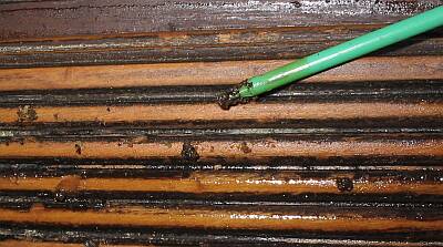
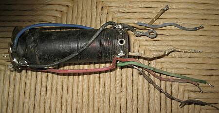 This is an RF coil,
with trimmers mounted on its top. I had to remove these coils because their
connection wires had cracked insulation, so bad that they shorted out everywhere.
This is an RF coil,
with trimmers mounted on its top. I had to remove these coils because their
connection wires had cracked insulation, so bad that they shorted out everywhere.
Interestingly, some colors of rubber insulation degraded much more than
others. Throughout the radio, the brown rubber is totally brittle, while
the blue and red are much better. Probably the kind of dye affected the
stability of the rubber. Also, the wires are in much better condition in
all those places where it doesn't get too hot, and where there is little
air circulation. It looks like strong ventilation brings in too much oxygen,
and the rubber gets oxidized!
I had to replace most of the radio's wiring.
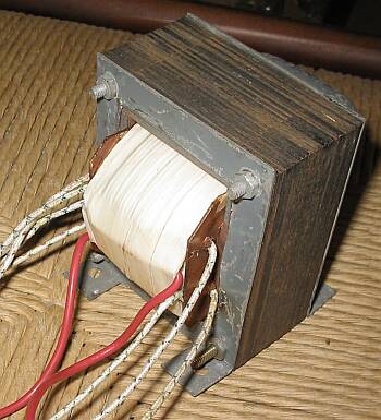 In the
course of the reconstruction of this radio, a power transformer had to
be custom-made. I do have a simple winding machine, which was given to
me by a ham radio friend, Enrique Villanueva, many years ago when I was
a student. This machine has proven enormously useful, many times!
In the
course of the reconstruction of this radio, a power transformer had to
be custom-made. I do have a simple winding machine, which was given to
me by a ham radio friend, Enrique Villanueva, many years ago when I was
a student. This machine has proven enormously useful, many times!
But first I had to get a suitable core. The space available is
quite tight for a transformer of this power rating (80 Watt), so I wanted
to use the biggest one that would fit. I asked several friends for old
transformers in the suitable range of sizes. Romelio Gajardo was the "winner",
giving me an old 220-110V autotransformer that had almost exactly the optimal
size. I took it apart, and rewound it for this radio.
The filament requirements were clear enough. But I had my doubts with
the high voltage. The service manual for this radio, however complete it
might be in most regards, does not give the voltage of the transformer's
high voltage winding! So I had to start from the voltages given for the
tube plates, add the drop for the speaker field coil, add an estimated
drop in the rectifier tube, consider the capacitor filtering effect, the
wire resistance, and so I arrived at 2 x 280V. I wound the transformer
for this voltage, and the radio is playing great with it. But the voltages
ended up a tad lower than those given on the diagram - the rectifier drops
more voltage than expected! Winding the transformer for 300V would have
been better. But 280V is close enough. I won't remake the transformer for
that small difference! It has a total of 3580 turns of wire, which even
using a machine take some time to wind!
After making this photo, the transformer was painted black With the
light yellow paper insulation, it looks quite antique!
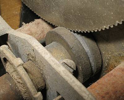 The mechanics
also required quite a bit of work. This detail shows the drive mechanism
of the variable capacitor. There is a vernier drive, with a rubber roller
connecting to a softly dented wheel. And this roller was dry, brittle,
and worn, so much so that it slipped without even trying to engage with
the teeth!
The mechanics
also required quite a bit of work. This detail shows the drive mechanism
of the variable capacitor. There is a vernier drive, with a rubber roller
connecting to a softly dented wheel. And this roller was dry, brittle,
and worn, so much so that it slipped without even trying to engage with
the teeth!
I considered just wrapping it in something, but after repairing the
vernier drive I caught flight, and opted for the correct way to repair
the roller.
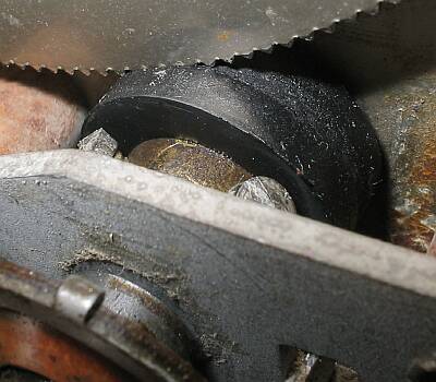 I went
to a store that sells all sorts of rubber pieces, and bought a door stopper
that was big enough to put in my lathe. I deep-froze it using freezing
spray, and turned it to slightly larger size than what the roller needs
to be. Then I put the brass sleeve in the lathe, ripped off the old bad
rubber, cleaned the rubber mounting surface with the lathe. Then I vulcanized
the new rubber piece onto the brass sleeve, with heat and sulfur. When
that was done, I again froze the rubber, turned it down to the exact size,
and then gave it a smooth surface by slightly melting it with a grinding
stone in a Dremel tool.
I went
to a store that sells all sorts of rubber pieces, and bought a door stopper
that was big enough to put in my lathe. I deep-froze it using freezing
spray, and turned it to slightly larger size than what the roller needs
to be. Then I put the brass sleeve in the lathe, ripped off the old bad
rubber, cleaned the rubber mounting surface with the lathe. Then I vulcanized
the new rubber piece onto the brass sleeve, with heat and sulfur. When
that was done, I again froze the rubber, turned it down to the exact size,
and then gave it a smooth surface by slightly melting it with a grinding
stone in a Dremel tool.
The result is just perfect! It works as it should, and several people
who have seen it just don't want to believe that this part isn't an original
Atwater Kent spare part!
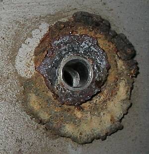 More rubbery
trouble: The soft, slotted rubber washers, which are used in almost all
radios to keep chassis vibration away from the variable capacitor, had
decomposed into a somewhat crystallized, rosin-like goo. I could find no
rubber that's soft enough for this purpose, and in most old radios these
washers need replacing. So I decided to solve the problem once for all
time!
More rubbery
trouble: The soft, slotted rubber washers, which are used in almost all
radios to keep chassis vibration away from the variable capacitor, had
decomposed into a somewhat crystallized, rosin-like goo. I could find no
rubber that's soft enough for this purpose, and in most old radios these
washers need replacing. So I decided to solve the problem once for all
time!
 Here you
can see the new washer. It's made from silicone caulk. This material has
precisely the right properties to be used in this application!
Here you
can see the new washer. It's made from silicone caulk. This material has
precisely the right properties to be used in this application!
Using my lathe, I turned some molds from polyethylene, which does not
adhere to silicone. Then it was just a matter of pouring silicone, letting
it set, take the new washer out of the mold, and pour silicone again. In
a matter of some days, I made all the washers I will ever need! Renato
also got some, since he too has radios that need new rubbers.
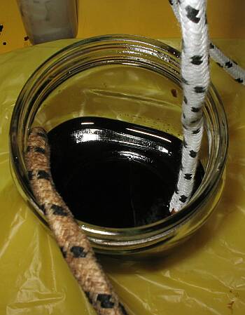 The radio came
with a plastic power cord from the 1960s or so. Ugly! I decided to give
it a new cord, a nice, fabric covered and brown one. But the only fabric
covered power cord I could find was white with black dots! So I bought
that, and dyed it with walnut extract. It came out quite decent, but not
perfect. Next time I do that, I will use a different dye, trying to make
it better!
The radio came
with a plastic power cord from the 1960s or so. Ugly! I decided to give
it a new cord, a nice, fabric covered and brown one. But the only fabric
covered power cord I could find was white with black dots! So I bought
that, and dyed it with walnut extract. It came out quite decent, but not
perfect. Next time I do that, I will use a different dye, trying to make
it better!
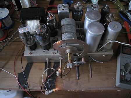 This is the
filament test! At last, the chassis was ready, reconstructed component
by component. I let the filaments run for some hours, to warm up the tubes
and activate the getters, so that any residual gas would be adsorbed before
applying high voltage.
This is the
filament test! At last, the chassis was ready, reconstructed component
by component. I let the filaments run for some hours, to warm up the tubes
and activate the getters, so that any residual gas would be adsorbed before
applying high voltage.
The dial lamps in this photo are 6.3V ones. They light as dimly as the
tube filaments. I later found the correct 2.5V lamps.
Meanwhile I tested the speaker, so I could go to the big test! But alas,
the speaker was dead...
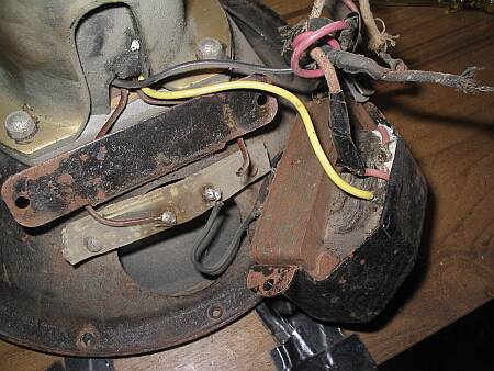 Here you can
see the sorry condition of the speaker wiring. A kludge of patches, held
together by more patches, and missing at least yet another patch because
there was still no continuity in the transformer primary...
Here you can
see the sorry condition of the speaker wiring. A kludge of patches, held
together by more patches, and missing at least yet another patch because
there was still no continuity in the transformer primary...
Fortunately the problem was just with the connection of the primary
winding to the terminal. I was able to dig into the transformer insulation
and fish out the tiny wire, reconnecting it. Then I tried my radio, and
it worked right away! It was a surprise to find that despite my extensive
disassembly, change of parts, wiring, and all, the radio actually held
its alignment well enough to work right away! But then I noticed
that the news that were coming out of the speaker were not local ones,
and that the lady talking did definitely have a non-Chilean accent. The
next revelation was that I was listening to a Spanish radio station! The
band switch just happened to be on short wave and this resurrected radio
was receiving Europe on a 1 meter long wire antenna, without even having
been realigned! WOW!
Even so, of course I realigned the set. The broadcast band dial was
a bit off the truth, and after 70 years and a complete reconstruction,
alignment is sure to be non-optimal. My first surprise was to find the
IF adjusted to 455kHz! That was the work of a previous repairer. He had
then tried to bring the dial into alignment by brutally tightening some
trimmers, to no avail, because this radio is designed for an IF of 472.5kHz!
I realigned the IF transformers to the correct frequency, and then the
rest of the adjustments were easy to do, with all the trimmers ending up
somewhere near midrange. As I aligned the set, it really came to
life! This thing is so sensitive, and has such good AGC action, that
on a 1 meter long antenna wire laid on the bench, it receives international
broadcast stations at the same volume control setting as a local station!
That kind of performance was not usual until many years later.
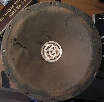 But
the sound quality was very poor. The speaker was scratchy, which was no
wonder, considering how the cone looked. I tried re-centering it, but there
was no way. The voice coil was bent, and always scraped at some place,
regardless of how I pushed and shifted it. The coil was non-original. The
cone had several patched rips, and some unpatched ones. The spider was
totally deformed, ending up in a position that left it no motion range.
After pondering the possibilities, I decided, with quite some pain in my
poor suffering heart, to part with the original Atwater Kent cone, and
re-cone this speaker.
But
the sound quality was very poor. The speaker was scratchy, which was no
wonder, considering how the cone looked. I tried re-centering it, but there
was no way. The voice coil was bent, and always scraped at some place,
regardless of how I pushed and shifted it. The coil was non-original. The
cone had several patched rips, and some unpatched ones. The spider was
totally deformed, ending up in a position that left it no motion range.
After pondering the possibilities, I decided, with quite some pain in my
poor suffering heart, to part with the original Atwater Kent cone, and
re-cone this speaker.
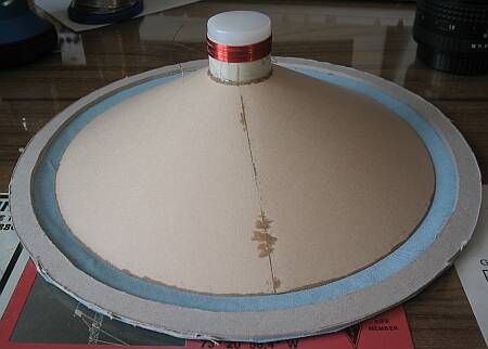 I made the cone
from the same stiff paper I use to print my business cards. I made a polyethylene
former for the voice coil, using the lathe, and made the coil, using an
old QSL card as material for the support. Fortunately I had just the right
size of wire at hand. The two layers of wire, measuring as much as the
width of the magnet poles, gave me precisely the 3.2 Ohm specified for this
speaker. The next smaller gauge of wire would have given close to 5 Ohm,
while the next larger one would be too thick to fit the gap!
I made the cone
from the same stiff paper I use to print my business cards. I made a polyethylene
former for the voice coil, using the lathe, and made the coil, using an
old QSL card as material for the support. Fortunately I had just the right
size of wire at hand. The two layers of wire, measuring as much as the
width of the magnet poles, gave me precisely the 3.2 Ohm specified for this
speaker. The next smaller gauge of wire would have given close to 5 Ohm,
while the next larger one would be too thick to fit the gap!
I first glued the fabric to the cardboard ring, then the cone to the
fabric, then the coil to the cone. During all this gluing, painstaking
care was applied to keep everything well aligned. The polyethylene former
was removed only after all gluing was done, so it could keep the coil perfectly
straight while gluing.
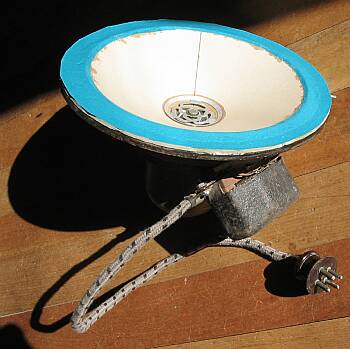 Here
is the rebuilt speaker! Shudder, those colors! Originally I had the noble
intention of spraying it black, but then I decided against this. The paint
might stiffen the cone, making it sound tinny, and anyway these colors
aren't visible when the radio is assembled.
Here
is the rebuilt speaker! Shudder, those colors! Originally I had the noble
intention of spraying it black, but then I decided against this. The paint
might stiffen the cone, making it sound tinny, and anyway these colors
aren't visible when the radio is assembled.
Instead, I exerted more care, colorwise, when replacing the speaker
cable. The original was beyond repair, with all the insulation cracked,
and the conductors shorted. I used plastic-insulated wires and sheathed
them in the fabric removed from a piece of power cord, dyed brown with
walnut extract.
With the repaired speaker, the radio was now sounding good! All the
scratchiness was gone. It was time to move to woodworking.
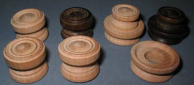 My radio had
no knobs. But Renato has an AK 206-D, which despite not being complete, does have most
of its original knobs! I borrowed his knobs, and copied them on the
lathe, making all the knobs my radio needed, and those that were missing
on his.
My radio had
no knobs. But Renato has an AK 206-D, which despite not being complete, does have most
of its original knobs! I borrowed his knobs, and copied them on the
lathe, making all the knobs my radio needed, and those that were missing
on his.
The original knobs were made of a dark wood. It might be walnut, but
I don't know. Anyway, I don't have any dark wood like that available here.
Whatever I used, I would have to dye it. Looking around for something suitable,
my eye fell on the humble broomstick in the corner of my workshop. That
broomstick was really begging me for the honor of donating part of itself
to the Atwater Kent legend! I grabbed the hacksaw... A minute later
the broomstick was 20 cm shorter, and my lathe went to work on the donated
organ, transforming it into one and a half sets of accurately original
Atwater Kent radio knobs!
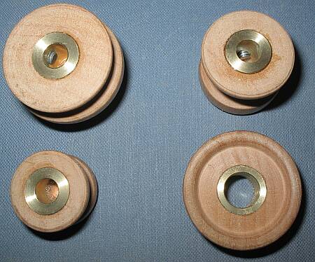 The knobs
got brass inserts with set screws. Of the original AK knobs, only the two
concentric ones on the tuning shaft have set screws, while the others are
simply pushed on. But with the heavily rusted shafts of my radio, push-on
knobs weren't a good idea. I fitted all the new knobs with set screws.
That's also easier to make than spring-loaded inserts.
The knobs
got brass inserts with set screws. Of the original AK knobs, only the two
concentric ones on the tuning shaft have set screws, while the others are
simply pushed on. But with the heavily rusted shafts of my radio, push-on
knobs weren't a good idea. I fitted all the new knobs with set screws.
That's also easier to make than spring-loaded inserts.
This photo shows one each of all four different knobs this radio uses.
The band switch and tone switch each use one like that in the upper right.
The tuning shaft is double concentric, for the vernier drive, and uses
the lower right knob for fast tuning and the lower left one on top of it
for fine tuning. The volume control, for symmetry, uses a single knob in
the same shape as the two tuning knobs combined. What a fancy way of maintaining
symmetry! It shows the Atwater Kent philosophy to perfection!
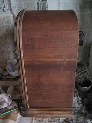
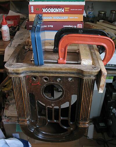 Here you can
see the cabinet, more or less as I got it. It's upside down here, in the
process of being re-glued. The entire lower section had come apart, and
every single layer of plywood had complete freedom. The whole box was a
very weak affair! I had to wiggle glue into each of the narrow slits between
each layer of plywood and its neighbors, and then compress the sandwich
to re-glue it all. Wooden blocks were wrapped in kitchen plastic and used
as pressure pads. The plastic won't bind to the glue.
Here you can
see the cabinet, more or less as I got it. It's upside down here, in the
process of being re-glued. The entire lower section had come apart, and
every single layer of plywood had complete freedom. The whole box was a
very weak affair! I had to wiggle glue into each of the narrow slits between
each layer of plywood and its neighbors, and then compress the sandwich
to re-glue it all. Wooden blocks were wrapped in kitchen plastic and used
as pressure pads. The plastic won't bind to the glue.
Note the red paint marks around the hole for the bandswitch. This radio
must have had a forgetful user. He painted the positions for long and short
wave in red paint over the radio!
 After re-gluing
all loose parts, and replacing a section of veneer that was missing from
the back of the rim, the detective work started. Too often I have refinished
radios, only to find that they ended up beautiful, but far from their original
look. With this nice radio, I absolutely wanted to make it look as original
as I can. But that isn't easy!
After re-gluing
all loose parts, and replacing a section of veneer that was missing from
the back of the rim, the detective work started. Too often I have refinished
radios, only to find that they ended up beautiful, but far from their original
look. With this nice radio, I absolutely wanted to make it look as original
as I can. But that isn't easy!
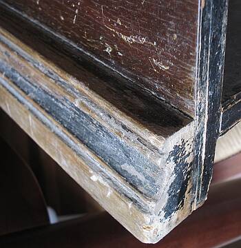
Look here, for example. The backside is painted black, no doubt about
that. The stripe along the molding looks black too, while the rest is walnut
brown, except where no finish is left. So, was the black stripe made with
the same paint used on the back? Apparently not: The paint on the back
dissolves very quickly in lacquer thinner, while the black stripe was very
slow to dissolve!
 Clearly, the
black stuff in the stripe is different from the brown further up. But is
it a different lacquer, paint, or just a thicker layer of lacquer? And
what dye did they use?
Clearly, the
black stuff in the stripe is different from the brown further up. But is
it a different lacquer, paint, or just a thicker layer of lacquer? And
what dye did they use?
Note the unglued plywood and veneer. This photo was taken before re-gluing
this.
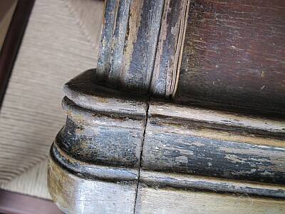
 This is a
detail of the left column. It looks like it had black dye in most of it,
but brown at the sides (left side here). All of that remains only in the
low areas; at the raised areas the finish was totally worn off. Later,
someone painted over it all, with a yellowish brittle stuff which I like
to call cacalaca.
Those of you who understand Spanish will know
what I mean!
This is a
detail of the left column. It looks like it had black dye in most of it,
but brown at the sides (left side here). All of that remains only in the
low areas; at the raised areas the finish was totally worn off. Later,
someone painted over it all, with a yellowish brittle stuff which I like
to call cacalaca.
Those of you who understand Spanish will know
what I mean!
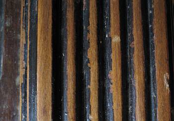
I took samples from various parts of the finish, analyzed them, looked
at them under different lights... and it was puzzling at best. The idea
I got is that these guys used Bitumen of Judea as a dye, and applied it
both as a paste filler, probably by hand with a rubbing pad, and also mixed
with the lacquer that was sprayed on. If any of my dear readers knows what
materials were used in the Atwater Kent factory, and on old radios in general,
I would love to hear about it!
 Anyway,
the finish had to come off. It was much to unevenly damaged to even think
about saving it. I applied a mix of solvents, and slowly the stuff came
off. I discovered that the radio had been painted over at least two
times, apparently one time with cacalaca and the other time
with a modern varnish. One of the painters had tried to remove the dark
finish, scraping parts of it away with a sharp tool, and leaving the rest.
It looked horrible. The other painter had just brushed varnish over everything,
even the escutcheon and the dial window! Fortunately, the grille cloth
escaped his brush.
Anyway,
the finish had to come off. It was much to unevenly damaged to even think
about saving it. I applied a mix of solvents, and slowly the stuff came
off. I discovered that the radio had been painted over at least two
times, apparently one time with cacalaca and the other time
with a modern varnish. One of the painters had tried to remove the dark
finish, scraping parts of it away with a sharp tool, and leaving the rest.
It looked horrible. The other painter had just brushed varnish over everything,
even the escutcheon and the dial window! Fortunately, the grille cloth
escaped his brush.
With lots of patience and an activated charcoal respirator, I dissolved
all that stuff and cleaned it away, with rags, paper towels, and plastic
tools.
 Under the very bad
finish was an almost perfect wood surface. The veneer on the sides and
top was perfect except for one small notch. The veneer on front hat a few
dents, but they came out beautifully with water. The moldings on the sides
were heavily injured: Someone had driven large nails to them, in diagonal,
to fix the radio to the desk! Either he used it on a boat, or he was very
afraid of thieves! I had to fill the nail holes with putty.
Under the very bad
finish was an almost perfect wood surface. The veneer on the sides and
top was perfect except for one small notch. The veneer on front hat a few
dents, but they came out beautifully with water. The moldings on the sides
were heavily injured: Someone had driven large nails to them, in diagonal,
to fix the radio to the desk! Either he used it on a boat, or he was very
afraid of thieves! I had to fill the nail holes with putty.
The columns were somewhat damaged from impact of assorted objects. I
reconstructed the worst areas with putty, and left the rest for the paste
filler.
The moldings on the sides and on the front are made from different kinds
of wood. The one on front is much better quality! This makes clear that
this cabinet was intended from the start to be finished in a quite dark
tone, the only way to disguise the different sorts of wood.
 The next
step was paste-filling the wood. I prepared a filler from standard, colorless
wood filler, mixed with a considerable amount of Bitumen of Judea. It produces
a tarry black paste that beautifully fills the pores of the wood with an
almost black tone, while giving a slightly more reddish than walnut color
to the rest of the surface. Then I smoothened the surface using very fine
steel wool. The wood filler is formulated to be easy to sand away, and
leaves the wood as smooth as baby skin. This is very necessary, because
the walnut veneer has large pores, and the side moldings are made of a
cheap wood that is very coarse. But sandpaper is too coarse a tool here!
The steel wool is just right. It also gets better into the corners and
the shape of the columns.
The next
step was paste-filling the wood. I prepared a filler from standard, colorless
wood filler, mixed with a considerable amount of Bitumen of Judea. It produces
a tarry black paste that beautifully fills the pores of the wood with an
almost black tone, while giving a slightly more reddish than walnut color
to the rest of the surface. Then I smoothened the surface using very fine
steel wool. The wood filler is formulated to be easy to sand away, and
leaves the wood as smooth as baby skin. This is very necessary, because
the walnut veneer has large pores, and the side moldings are made of a
cheap wood that is very coarse. But sandpaper is too coarse a tool here!
The steel wool is just right. It also gets better into the corners and
the shape of the columns.
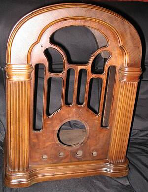
This photo shows the cabinet after smoothing it. I have seen many people
who reach this stage, say "wow, that's beautiful", spray on a coat of clear
lacquer, and assemble the radio. The web is full of such improperly restored
radios!
 The next step
in a correct restoration is staining. Finally I found a walnut stain that
can be dissolved in lacquer thinner. I used this stuff to dye some lacquer,
and sprayed several layers of it, masking areas as required, to get all
the colors as close as possible to the original. While working, I used
calibrated photos of my radio before stripping, of Renato's radio, and
some photos which I found on the web, showing unrestored radios of this
and other models, which come in the same cabinet. After lots of work,
I think I have come rather close to the original colors!
The next step
in a correct restoration is staining. Finally I found a walnut stain that
can be dissolved in lacquer thinner. I used this stuff to dye some lacquer,
and sprayed several layers of it, masking areas as required, to get all
the colors as close as possible to the original. While working, I used
calibrated photos of my radio before stripping, of Renato's radio, and
some photos which I found on the web, showing unrestored radios of this
and other models, which come in the same cabinet. After lots of work,
I think I have come rather close to the original colors!
The knobs were soaked in walnut extract, then given the same treatment
as the cabinet, starting from the paste filling step.
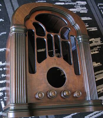
This photo shows the radio in its final colors, before spraying on a
few dozen thin coats of clear lacquer, which are necessary to give it a
hard, abrasion-resistant surface.
 And here is the
completely restored radio! But I had to do a few more things, easy things
really, before reaching this stage. One was restoring the escutcheon and
crystal. Some earlier "restorer" had brushed varnish over both. The varnish
had attacked the celluloid window, and glued everything together. I separated
the window from the frame by mechanical means, soaked the frame in paint
remover, and polished the window with 3M polishing compound, medium grade
first, then fine grade. It came out good enough, if not perfect, and certainly
better than replacing it.
And here is the
completely restored radio! But I had to do a few more things, easy things
really, before reaching this stage. One was restoring the escutcheon and
crystal. Some earlier "restorer" had brushed varnish over both. The varnish
had attacked the celluloid window, and glued everything together. I separated
the window from the frame by mechanical means, soaked the frame in paint
remover, and polished the window with 3M polishing compound, medium grade
first, then fine grade. It came out good enough, if not perfect, and certainly
better than replacing it.
The brass escutcheon apparently was originally stained black by a chemical
process. Someone later scraped away most of the black, probably thinking
the escutcheon was originally bright metal! I had to give it back its color.
But chemical stains work by attacking the metal. Fine, in a well controlled
factory process, but to restore an antique I prefer something that's reversible
if it goes wrong! So I sprayed it with black paint, then cleaned the paint
off the raised areas, and then sprayed it with clear lacquer for protection.
Using natural walnut extract for the power cord seems to have been a
bad idea - in this photo it looks too light! But in natura it looks
quite good. Anyway, next time I will use a stronger dye. Note the power
plug. It's courtesy of Renato, once again! I don't have a guarantee that
it is like the original this radio had, but it belongs roughly into the
time, and is US-made for export.
The antenna and ground wires are true, real, original 2004 vintage fabric
covered wire: I bought an assortment of strings and cords in a small store
devoted to selling sewing supplies, extracted the core of them and used
the sheath to cover some thin wires. :-)
The grille cloth was mechanically in quite good condition, only the
lower ends were frayed, because the earlier restorers didn't bother to
fix the backing to the cabinet after putting the cloth and speaker back
in. So the cloth flapped with the vibration of the speaker, and frayed.
But you have to look very closely to notice that, so I don't consider it
a problem. The bad thing with this cloth was its color: It had faded so
severely that it ended up almost white! The radio must have spent a long
time in the sun. The areas protected by wood had a very much darker color,
which I assume is the one the cloth should have.
My solution to the problem was spraying the cloth with highly diluted
Bitumen of Judea. It nicely gave the cloth a color that's reasonably close
to the original, complete with some of its sheen. The cloth is made of
two different kinds of fibers, which accept the color differently, so even
the texture of the cloth was recovered! And since these are natural fibers,
using lacquer thinner instead of water to carry the dye avoids shrinkage
and dulling of the cloth. This rejuvenating treatment was carried out without
removing the cloth from the backing.
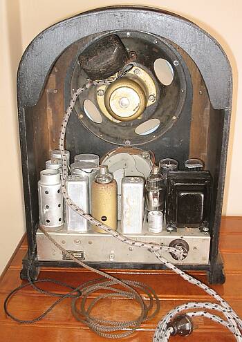 The inside view.
The most non-original parts on the chassis are the two tube shields on
the left. Unfortunately, this radio had only one of the original three
golden tube shields left. So I used standard shields, straight out of Renato's
stock, at least as a provisional solution until I find the originals, or
make replicas.
The inside view.
The most non-original parts on the chassis are the two tube shields on
the left. Unfortunately, this radio had only one of the original three
golden tube shields left. So I used standard shields, straight out of Renato's
stock, at least as a provisional solution until I find the originals, or
make replicas.
My new power transformer seems to be a tad larger than the original,
but not enough to look out of place. The electrolytic capacitor on its
left side is not nearly as long as the original, but considering that the
original was no longer there, and that I had this capacitor, which fit
the hole, had the correct capacitance and voltage ratings, and was in perfect
condition, I used it.
The triple electrolytic is still there, but totally dead, so it's disconnected.
Small modern caps, well hidden under the chassis, do the work. I decided
in favor of this solution, rather than cutting the old cap open and installing
the new ones inside. That can always be done later, if the next restorer
70 years from now decides to do so. But turning back is not possible, after
cutting that cap open.
There are specks of rust on some places, and I did not redo the paint
job on the speaker structure. So the radio does not look new. It looks
like a reasonably well treated 70 year old radio inside. The chassis has
rust only where it has been deeply scratched. The rest is impressively
shiny, a result of Atwater Kent's nickel-over-cadmium plating. On
the outside, of course, the new finish is obvious. But considering the
condition of the old one, there was no choice.
 Restoring
this piece of radio history was a long process. From the moment Alain got
me this radio, two years passed with no activity other than gathering the
parts and information needed for a good restoration, and thinking about
how I would do each part of the process. And then, the actual work took
every bit of my spare time for about four months! That's well over 300
hours of work, making this the most time-consuming restoration since I
started this hobby. I don't regret it - any time spent working on an Atwater
Kent radio is time well spent!
Restoring
this piece of radio history was a long process. From the moment Alain got
me this radio, two years passed with no activity other than gathering the
parts and information needed for a good restoration, and thinking about
how I would do each part of the process. And then, the actual work took
every bit of my spare time for about four months! That's well over 300
hours of work, making this the most time-consuming restoration since I
started this hobby. I don't regret it - any time spent working on an Atwater
Kent radio is time well spent!
My thanks go to Alain, his former landlord whose name I don't know,
to Renato, Romelio, and everyone else who helped me getting parts, information,
and courage to rescue this fine piece of radio history!
If you want to use the beautiful face of the Atwater Kent 206 as a background
image for Windows, or whatever, be my guest. You can click this photo to
get a 1024x768 pixel version of it.
Back to homo ludens radiohistoricus.