Practical transformer winding
 In the good old times it was a matter of fact that
every electronic hobbyist or technician would wind himself any power
transformers he needed, and rewind any that burned out. Unfortunately, nowadays
transformer winding is fast becoming a lost art, and I have seen many people
despair about where to find some very specific transformer, or pull their hair
out about the cost of having one professionally wound to specifications.
In the good old times it was a matter of fact that
every electronic hobbyist or technician would wind himself any power
transformers he needed, and rewind any that burned out. Unfortunately, nowadays
transformer winding is fast becoming a lost art, and I have seen many people
despair about where to find some very specific transformer, or pull their hair
out about the cost of having one professionally wound to specifications.
Since I started in electronics, as a 12 year old boy, I have always wound my
own transformers. I started using the basic, but useful instructions provided in
The Radio Amateur's Handbook of the time, and later I came to better understand
how transformers work, which enabled me to optimize a given transformer for
the intended application.
Following a request by many readers of my web site, I've added this page, which is
complementary to the previously published Transformers and coils. You should first read
(and understand!) that page, before trying to design any transformer. Then
come to this more practically-oriented page, to learn some tricks and hints
about the design process, and about hands-on winding.
This page addresses mainly single-phase power transformers in the power range
from about 1 watt to 10,000 watts, operating at line frequencies, but much of
what's described here can be applied to a wide range of other transformers
too.
 Let's start with the materials. To make a typical transformer, you need
the iron laminations for the core, enameled copper wire of several different
diameters for the windings, a bobbin (or some material to make one), insulating
material to apply between wire layers, between windings, around
the whole winding assembly, and on exposed wires, and in most cases
it's also a good idea to use an impregnation varnish.
Let's start with the materials. To make a typical transformer, you need
the iron laminations for the core, enameled copper wire of several different
diameters for the windings, a bobbin (or some material to make one), insulating
material to apply between wire layers, between windings, around
the whole winding assembly, and on exposed wires, and in most cases
it's also a good idea to use an impregnation varnish.
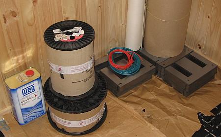
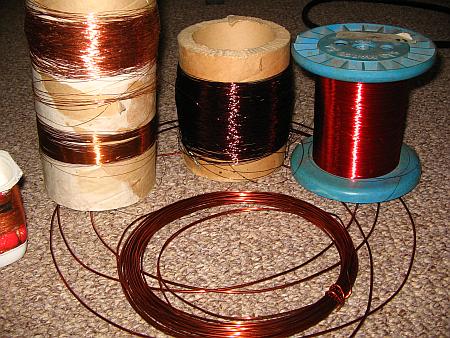
The photo here shows several stacks of iron E-I laminations, two coils of
wire (with cardboard protecting the wire from damage), one roll of thick, stiff
Pressspan, another roll of NMN laminate (we will soon see what that is), two
small bundles of spaghetti for wire protection, and a can of transformer
varnish. Add to this some glue, cotton straps, ropes, adhesive tape, terminals,
bolts, angle iron, and other small material, and that's it.
All these materials are sold by companies specializing in transformers and
parts for transformers. Enameled wire is also sold by many other distributors,
but is usually cheapest at the places that sell it together with the other
materials. You will have to dig into the phone book or some other directory to
find these companies, since they don't usually have a shiny nice store in the
downtown shopping mall!
Transformer iron is an alloy of iron with silicon and some other minor components. It's
characterized by a relatively high permeability, very high saturation flux
density, relatively low hysteresis loss, and relatively high specific resistance.
This latter factor, along with the practice of using the material in
thin, insulated sheets, reduces the power losses produced by eddy currents.
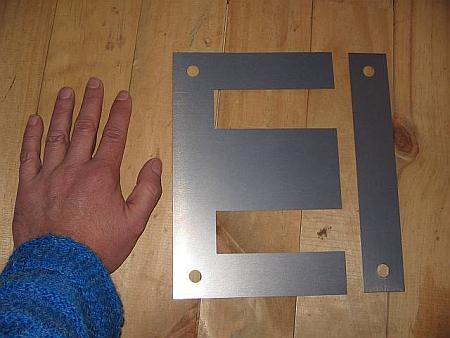
The most common shape of these sheets is shown at right.
It's the classic "economy E-I" shape. Why it's called E-I should be pretty
obvious when looking at the photo! But the explanation for "economy" might be a
bit more elusive: It's because at the exact proportions shown in the photo, the
I's are nothing else than the cutouts to make the windows in the E's, when two
E's are cut facing each other! This allows stamping E's and I's out of a large
steel sheet, without any wasting of material, except for the little round bits
cut out of the bolt holes. By the way, small laminations often don't have such
bolt holes, and such cores are held together by clamps instead of bolts, or even
welded.
The lamination in the photo is a large one, as the
comparison with my hand shows. It's an E80 (the center leg is 80mm
wide), typically used for transformers in the 3 to 10 kilowatt range!
In any E-I lamination you are likely to encounter, the
center leg is twice as wide as each of the other parts. This is because the
entire magnetic flux has to go through the center leg, but then splits up,
with one half of the flux returning through each of the side legs. If you
ever come across a lamination that has all three legs of the same width,
then you are looking at a lamination intended for three phase
transformers!
Such an economy E-I lamination like shown here has
completely fixed proportions, beyond the rule above, that stem from the need to
cut the I out of the winding window of two E's facing each other: If the center
leg is 2 units wide, then the window is 1 x 3 units, the total E is 6 x 4 units,
the I is 1 x 6 units, and so on.
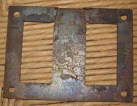
Not all laminations follow the
"economy" proportions, though. Here is an example of a lamination that
comes in one piece, instead of being divided into an E and an I, and that has
the windows proportionally much larger than the E-I lamination shown above. Such
a lamination is a bit more expensive to make, because the steel cut from the
windows is wasted, unless the manufacturer can find some other use for it.
But being able to accomodate a much large winding assembly, it has some
advantages in certain cases.
These "non-economy" laminations were quite usual in
Europe, many years ago, but nowadays copper is so much more expensive than
steel, that transformers are usually designed to use more steel and less copper.
And for that goal, the economy lamination is very well suited. So you won't very
often come across a lamination like this, unless you are restoring antique
equipment.
The laminations should be thin, and reasonably well
insulated from each other, to reduce eddy currents to an insignificant value.
Typical thicknesses vary from 0.2 to 0.5mm, but higher frequency transformers
(audio) use much thinner ones, while extremely large transformers might use
slightly thicker ones.
The insulation is often applied at the factory that
makes the big rolls of steel sheet, even before stamping the E's and I's.
Different kinds of insulation are used: A thin oxide layer, a thin layer of
enamel, or any of several chemical processes. Antique transformers
sometimes even used very thin paper!
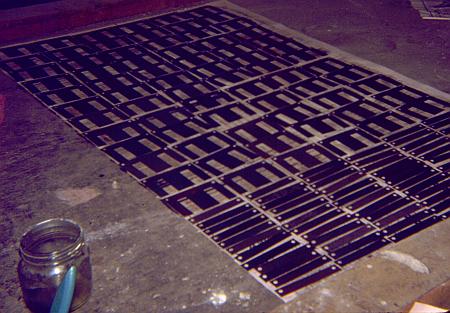
When I was young, patient and overly eager to do
things right, I painted each and every E and I for my transformers, using
diluted transformer varnish, to make a thin, nice layer. The photo shows the
steel for a 200 watt transformer, drying. Later, getting old and lazy, I noticed
that the layer of rust on old, recycled laminations is more than enough
insulation, and that the very thin and imperfect insulation that comes on new
laminations is enough too, even if it takes only a light scratch with the
multimeter's test probe to puncture it and get through to the steel. We don't
need perfect insulation between the sheets! We only need enough resistance to
reduce eddy currents to a low level.
Transformer steel is not all born alike.
Manufacturers will provide data sheets about their products (often on their
web sites), where you can see what they offer. There are usually many grades,
with vastly different loss characteristics. At a given flux density and
frequency, a good material might have ten times less loss than a cheap material!
So it pays to look, investigate, and decide intelligently what to buy.
Thinner sheets normally have lower loss, and the rest of the secret lies in the
exact alloy. In any case, you need to know what material you have, to be
able to make a meaningful transformer design!
Some transformer steel is grain-oriented. That
means that when rolling the steel sheets, a process is used to align the
crystalline grains in the direction of the rolling. This kind of material has
particularly good behavior when the magnetic flux is aligned with the
direction in which the sheet was rolled, but is worse than standard
material in the perpendicular direction. Such grain-oriented material is ideal
for toroidal cores, which are made by coiling up a long strip of steel, but is
not a large improvement for E-I laminations, because in these a significant
portion of the material has to work with the flux perpendicular to the rolling
direction.
Enamelled copper wire comes in many different diameters,
and with several different kinds of enamel. The diameters vary from less
than that of a hair, to about that of a child's finger. Different standards
exist for the wire diameter. A very common one is American Wire Gauge, shortened to AWG, which is
used in much of the world. Britain has its own standard, and in many countries
the wire is specified simply by its diameter in millimeters.
Thick wires usually are coated with a sort of enamel
that is very tough, an excellent insulator, highly heat-resistant, highly
resistant to solvents, and that clings to copper even better than dirt does to
children! This enamel is usually yellowish clear, so that the wire coated in it
looks mostly copper-colored, but many exceptions exist. To solder the ends of
these wires, it's necessary to scrape off the enamel, using a sharp knife
or similar tool. This procedure would be too difficult with a thin, fragile
wire, so that these thin wires are instead covered with an enamel that
has most of the same characteristics of the other one, except the heat
resistance: It will melt and turn into solder flux at a temperature a common
soldering iron easily achieves! This allows easily soldering these wires,
without previously stripping them. But transformers using this latter kind of
wire enamel cannot survive temperatures as high as those using only the former
kind of wire enamel. The red wire on the right side in this photo has this kind
of enamel. But be careful with colors! The clear wire on the extreme left
side also has solderable enamel, while the dark violet one in the middle is
of the non-melting variety!
The thickness of the enamel layer depends on the wire
thickness, the manufacturer, and can sometimes be chosen: Some manufacturers
will offer the wire with seeral different thicknesses of enamel. In any case,
the diameter specified by a certain AWG number refers to the copper diameter, so
that the complete wire, with enamel, will be slightly thicker than what the AWG
standard tells!
 Here is a wire table for AWG wire. It shows the AWG
number, the diameter in millimeters excluding the enamel, the approximate
typical total diameter including the enamel (but this varies somewhat), the
cross sectional copper area in square millimeters, the area of the square of
window space occupied by that wire in a transformer (including the enamel, of
course), the current carrying capacity at a typical, average value of current
density, the resistance in ohms per meter, and finally how many meters of that
wire come in one kilogram, because enamelled wire is usually bought by
weight, not length.
Here is a wire table for AWG wire. It shows the AWG
number, the diameter in millimeters excluding the enamel, the approximate
typical total diameter including the enamel (but this varies somewhat), the
cross sectional copper area in square millimeters, the area of the square of
window space occupied by that wire in a transformer (including the enamel, of
course), the current carrying capacity at a typical, average value of current
density, the resistance in ohms per meter, and finally how many meters of that
wire come in one kilogram, because enamelled wire is usually bought by
weight, not length.
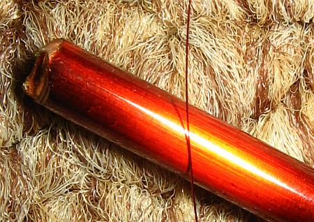
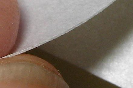
This table has wires from AWG #1 to #40, and for the
thickest ones I didn't calculate all data. But you should be aware that there
are wires exceeding this range! The thinnest I have ever used was #46. It breaks
when you blow at it! The photo here shows a #39 wire lying on a #7 wire. The
hairy thing below is my floor carpet. Note that even this #39 wire is not much
thicker than the hairs of this carpet!
It's interesting to note that every three AWG numbers,
the cross sectional area exactly doubles. Any deviation from this in my table is
due to approximation errors.
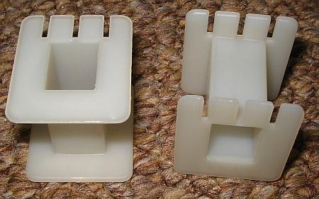
Modern transformers of small to moderate size are
usually wound on plastic bobbins. Here you can see simple ones. Some bobbins
have pins or terminals molded into them, others have one or two divisions. Some
don't have the slits for terminals, which the ones shown here do have.
Typically for a given size of E-I laminations, bobbins
will be available in two or three sizes, accomodating different numbers of steel
sheets. So you can vary the amount of steel in your transformer not only by
choosing the lamination size, but also the height of the lamination stack!
Here is a little transformer using a divided (or
split) bobbin. This is very practical, because it completely separates the
primary from the secondary winding, making it much easier to achieve the degree
of insulation required for safety. More about that later.
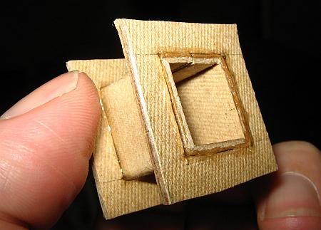
If you cannot find a plastic bobbin in the proper size,
don't despair! Bobbins can be easily made from materials such as strong
cardboard, or Pressspan, which is nothing else than a particularly strong
cardboard.
The bobbin shown here was made from 1.5mm thick
Pressspan, which is really too thick for this small bobbin, but I had nothing
better on hand. The pieces are cut to size using a sharp knife (X-acto or the
like), and glued together with cyanoacrylate adhesive (instant bonder). The
clever structural design of this super high tech bobbin holds it together
perfectly while the glue sets!
You must make the inner dimensions of the bobbin core a
tad larger than the transformer center leg, but JUST a tad, no more, unless you
want to waste valuable winding space! The sides can be made pretty tight to the
size of the laminations, because if they don't fit at the end, they are
easily enough cut or filed down, even after the winding has been made. But
the length of the bobbin must be smaller than the window length of the core, by
as much as 2 or 3%, plus any tolerances of your manufacture! Because it is
critically important that the E's and I's can touch each other properly,
without being kept separated by a bobbin that deformed during winding, and
grew!
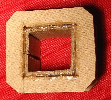 Be sure to at least break the corners as shown here, or even better, round them
off. Otherwise the wire is guaranteed to tangle at the sharp corners during
winding, and a wire loop sticking out of the completed winding can ruin the
whole thing!
Be sure to at least break the corners as shown here, or even better, round them
off. Otherwise the wire is guaranteed to tangle at the sharp corners during
winding, and a wire loop sticking out of the completed winding can ruin the
whole thing!
Note that the junction of the bobbin's center piece is
placed in the middle of one side, and not in a corner. It's next to impossible
to produce a reasonably symmetrical and precise bobbin when placing the junction
in a corner.
If the material is thin compared to the bobbin size, the
junction should be made by overlapping the material. Of course, the overlapped
junction is always placed on one side that will end up outside the core window,
so that the added bulk has little detrimental effect.
To bend this thick material in reasonably clean right
angles, my technique is to use a sharp knife to cut out a 90 degree wedge from
the inside, along each bend line, leaving only the outer third of the material
intact. After that admittedly cruel treatment, the Pressspan eagerly
bends to my will.
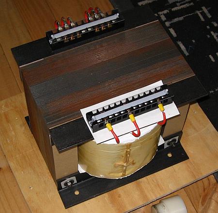
Most antique transformers, and many of the larger modern
ones, don't use a real complete bobbin. Instead, they use only the center
former, and no sides at all! It takes some tricks and practice to wind a
transformer like this without having the whole thing come apart many times over
during winding, but for people who have acquired enough practice, it's faster
than making a real bobbin!
Further down, I will show you a trick to make this kind
of transformer, with high quality.
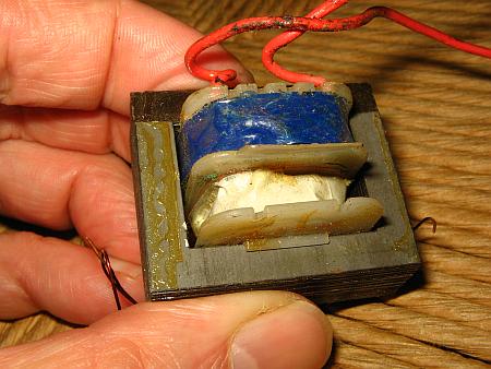
Note in this photo how the Argentinian maker of this
transformer (back in 1931!) used insulating material of several different
thicknesses for the bobbin center, the interlayer insulation, the interwinding
insulation, and the terminal support.
You might ask why any insulation material is required at
all, if the wire is insulated by its enamel layer! Well, the enamel is very
thin, and easily scratched. It might survive as much as a few thousand volts,
but it might also break down with a lot less! It depends on type, condition,
thickness, temperature, and other factors. So, wherever the voltage can exceed a
few tens of volts, some additional insulation needs to be used. Specially
between the primary and secondary, safety regulations ask for an insulation good
for at least 4000 volts, to avoid electrocuting somebody when there is a
lightning transient on the AC power network.
In antique transformers, the most usual insulating
material was paper, impregnated with something like
beeswax, tar or the like. This impregnation had several purposes:
Mainly, it would seal the pores of the paper, making it a really good insulator,
while without the impregnation it would only insulate as well as the same
thickness of air! But in addition, it kept moisture out, it helped stick the
thin wires in place during winding, and it improved the thermal conductivity of
the completed winding assembly.
It was also quite sticky, dirty, messy and gross.
Modern insulating materials are far superior. Plastic
sheets such as Mylar provide excellent dielectric strength and have no pores, so
they require no impregnation to realize their high degree of insulation.
Nomex instead, with its fibrous structure, behaves like paper, but both
Nomex and Mylar are much better than paper at surviving high temperatures! This
is a key characteristic of insulating materials: The temperature class. It's
coded with a letter. Paper would have an A or B rating, telling that it is
fine for temperatures not much above that of boiling water. Different plastic
insulation materials instead are routinely available in classes as high as F, G
or even H! They can safely run much hotter than paper can.
 The
photo shows an NMN insulating sheet. This is a sandwich of a Mylar sheet
embedded between two layers of Nomex. The Nomex will eagerly soak up and
distribute the impregnation varnish (or the oil, in an oil-inmersed
transformer), while the Mylar will provide safe insulation even in places that
for any reason stayed dry! I love this material. It's thermal class G, if I
remember right.
The
photo shows an NMN insulating sheet. This is a sandwich of a Mylar sheet
embedded between two layers of Nomex. The Nomex will eagerly soak up and
distribute the impregnation varnish (or the oil, in an oil-inmersed
transformer), while the Mylar will provide safe insulation even in places that
for any reason stayed dry! I love this material. It's thermal class G, if I
remember right.
Insulation materials come not only in many different
variants, and temperature classes, but of course also in many different
thicknesses. You choose the proper thickness so that it has enough dielectric
strength and mechanical strength, without taking up an undue portion of your
valuable window space!
Despite all modern materials, good old paper and
cardboard is still used sometimes. Mostly in its form known by the German word
Pressspan, which means "compressed chips", and is simply a very dense paper
or cardboard.
It's very good practice to soak a completed transformer
in some impregnation varnish. It will form fillets around wires, papers, and
anything else. It will improve the insulation, make the transformer highly
moisture-proof, glue everything together so that nothing can rattle, come loose,
or chafe through, it will improve thermal transfer, and so on.
Varnish comes in several thermal classes, just like the
insulation material, and also it comes in variants that dry at high temperature,
or at room temperature. My experience is that no varnish ever fully dries at
room temperature, and when you start using the transformer and it warms up, the
varnish inside will start drying, and stink! So, it's necessary to apply heat
anyway, regardless of what sort of varnish you use.
Now that you have turned into a person very
knowledgeable about transformer materials, let's turn to those pesky
questions such as "how many turns do I have to wind?" or "what
wire size?" or "how much power will I get?"
There are three typical situations:
1. You need to repair/rewind a transformer that burned
out.
2. Your want to rewind an existing transformer, to
produce the voltages and currents you need, which are different from the
original ones. A variation of this case is when you want a certain voltage, at
the highest current that transformer can provide.
3. You have fixed specifications, want to design a
transformer to optimally meet them, and you will buy the core and all other
materials.
 Let's start with the first case. You MUST
find out why that transformer failed! A correctly designed, correctly built and
correctly used transformer is, for all practical ends, eternal. If it failed,
there is a reason. If you know that the transformer was shorted, overloaded for
a long while, exposed to intense lightning transients, thrown into water, gnawed
through by rats, exposed to corrosive substances, or anything like that, then
your best approach is to unwind it, count the turns, measure the wire sizes, and
rewind it exactly as it was originally made.
Let's start with the first case. You MUST
find out why that transformer failed! A correctly designed, correctly built and
correctly used transformer is, for all practical ends, eternal. If it failed,
there is a reason. If you know that the transformer was shorted, overloaded for
a long while, exposed to intense lightning transients, thrown into water, gnawed
through by rats, exposed to corrosive substances, or anything like that, then
your best approach is to unwind it, count the turns, measure the wire sizes, and
rewind it exactly as it was originally made.
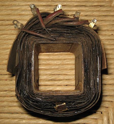
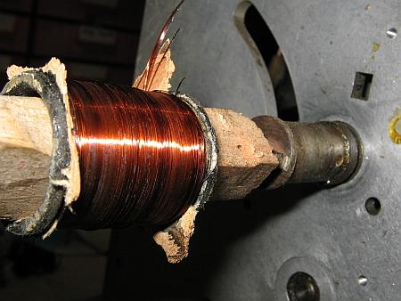
The photo shows an antique speaker field coil,
mounted in my winding machine. I unwind coils by pulling off the wire while
having the thing spin in the machine, so that the turns counter in the machine
will do the pesky job of keeping count. The problem, as illustrated here, is
often that thin wires won't come off nicely! They are stuck in place, and will
break, then entire chunks of wire will come off all together. This often makes
it hard to accurately count the turns.
In such cases you might simply estimate how many turns
you didn't count. Or you can collect all the pieces of wire you removed, weigh
them, calculate the amount of wire from there, and calculate the turns number
from it. Or, instead of unwinding the coil, cut it with a knife or better a
Dremel tool, remove it in one block, measure the cross sectional area of the
entire winding, then remove a little piece of wire to measure the diameter, and
finally calculate the number of turns from this. Any of these methods will
usually be precise enough for non-demanding applications, and none of it will be
precise enough when you need anything critical.
By the way, do you know how to precisely measure the
diameter of a thin wire, when you don't have a micrometer screw? Simple: You
wind 10 or 20 or even more turns tightly on a former (such as a screwdriver
stem), measure the length of the coil with a common ruler, then divide by
the number of turns to get the wire diameter. It's highly accurate. Sometimes
it's even better than using a micrometer screw, which can flatten the wire if
you apply too much torque!
But there are cases when you have a burned transformer,
and no good reason why it burned. It might have been a manufacturing defect, a
huge transient, an overload that went undetected, but maybe - the Gods of
Electromagnetics forbid - that transformer might have been misdesigned! In that
case, painstakingly rewinding it with the same wire gauges and turn numbers
as original, will only produce a transformer that will fail again. So, if
you don't know why a transformer failed, re-do the design, and compare your
results with what the manufacturer did! Many manufacturers are cheapskates, and
use substandard transformers, in the hope that most clients will never use them
intensively enough to blow them up! This sends you straight to the section about
the third case, further down this page!
In the second case, when you want to rewind an existing
transformer for new output values, very often the transformer will already have
a properly wound and healthy primary winding. In such a case, keep it! There is
no point in unwinding and rewinding the primary, if it is fine. The calculation
work for such a transformer is quite simple: Before taking it apart,
measure the voltage delivered by the secondary. Disassemble it, unwind the
secondary, counting the turns, and calculate the number of turns per volt from
this. Calculate the new number of turns you need for your desired voltage.
Calculate what's the largest wire size that will comfortably fit in the
available space. Get the wire, wind it, and assemble the transformer. The power
rating will be the same as before, and this allows you to calculate the current
you can safely draw, at your new voltage.
And if you also want a new primary, well, do the same as
above, but unwind and re-wind all windings, according to the value of turns per
volt you found out!

Do you know what you can do with all that wire you
remove from old transformers? Well, a super trendy wig, like the one shown here,
modelled by my sister, is sure to catch everybody's attention! Otherwise,
there isn't really much use for such wire. It comes out totally kinked,
stretched, broken, scraped, with varnish, wax or tar sticking to it. Don't even
dream about ever re-using it in any other transformer!
OK, now it's time to really start designing a
transformer. Because this is what you have to do in case 3, which is essentially
creating a transformer from scratch. I hope you are still fresh and aware of
everything you learned in Transformers and coils, because you will need
it here to understand what's going on.
The design process starts with guessing the size of core
you need, for the power you want. If you are experienced in electronics, you
will be able to make a reasonably close first guess. Otherwise, use the data
given by core manufacturers to get this first guess.
The core chosen will have a certain cross sectional
area, and will have a certain window area. The two multiplied are the "area
product", which can be related to the approximate power capability, with a
reasonably simple, but nonlinear curve. This curve also depends on the quality
of the core material, and several other factors.
The next step is calculating how many turns per volt you
need on this core. To this end, you have to decide how much flux density you
will put through your core, and then you can apply the equations from Transformers and coils. The optimal flux
density might be anything from 0.8 to 1.6 Tesla, and sometimes even outside this
range! General rules of thumb are these:
- Larger transformers use lower flux densities.
- Better core material uses higher flux densities.
- Transformers that are always energized, but rarely
used at full power, use lower flux densities.
- Likewise, transformers that work at full power
whenever energized, use very high flux density.
- Forced air cooled transformers use higher flux
density.
- Oil-immersed transformers use even higher flux
density!
- Higher flux density produces better voltage
regulation.
- Lower flux density produces less base loss.
- Lower flux density is less likely to produce humming
noise, and magnetic stray fields.
- Lower flux density produces lower iron loss, but
higher copper loss.
I have seen many text books giving design equations that
result in a flux density of 1 Tesla in each and every transformer you
calculate by them, like if that were a sacred rule! If you come across any such
book, BURN IT! It's nonsense! While 1 Tesla indeed tends to produce a workable
transformer in most cases, in at least 70% of all situations it's far
enough from the optimal value to warrant some effort toward optimization!
Specially in small transformers, and in those using the better core
materials.
So, I suggest to start with a value chosen from the
rules above, and then calculate the transformer based on this value, analyzing
the losses, heating, voltage drop, efficiency, and so on. Then change the flux
density, by 10 or 20%, and re-do all the calculations. You will see what I mean!
There is a clear optimum value for flux density in each particular case, and
this value is very often sufficiently removed from 1 Tesla to make you wonder
why some book authors still copy that "magic number" from other, long gone
authors! Most likely they have no idea about the matter they are copying.
That said, sometimes I do wind my transformers for 1
Tesla, because there are cases when this is really a good value!
The loss calculation isn't very hard: The manufacturers
of transformer steel specify the loss of their products, as a certain
amount of watts per unit of volume or weight, under certain conditions of
frequency and flux density. And the better of these data sheets also
contain curves, or give equations, to calculate the loss under different
conditions. That's about the iron loss. The total loss of the transformer also
includes the copper loss, which is caused simply by the current flowing through
the resistance of the wire. For a given flux density you get a certain number of
turns per volt, this allows you to calculate the total turns in each winding.
Dividing the available window cross section between these wires, insulation,
bobbin, and inevitably wasted space, you get the wire cross sections. From the
dimensions of the core, you can then calculate the total wire length, from this
and the cross sections you calculate the resistances of the windings, and from
that and the currents you calculate the power loss. It's easy!
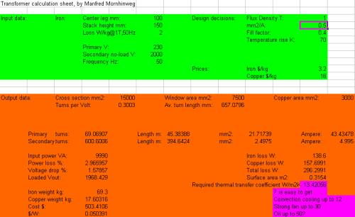 What? You are banging your head against the
wall? Come on! Don't cry! I have prepared an Excel sheet for you, which
takes care of these calculations! It's really too time consuming to do all this
math step by step, every time. Click on the screenshot at right to get the Excel
file, and then play with it as you continue reading.
What? You are banging your head against the
wall? Come on! Don't cry! I have prepared an Excel sheet for you, which
takes care of these calculations! It's really too time consuming to do all this
math step by step, every time. Click on the screenshot at right to get the Excel
file, and then play with it as you continue reading.
In this sheet, you enter your data in the green area,
and watch what happens in the orange one. The first three values you have to
enter are the ones that specify the core. First is the center leg width of the
lamination used, in millimeters. The 100mm width given in the example is a
pretty large lamination. You will typically use values between 12 and 50mm. The
sheet is based on the proportions of the economy E-I core, so that you don't
need to enter any other dimensions of the lamination. If you happen to be using
a lamination that has different proportions than the economy E-I,
you should still enter the width of the center leg, but later you will need to
manually compensate for the larger available window, by increasing wire size
beyond that calculated by the sheet, reducing the copper loss, and so on.
The second value you have to enter about the core is the
stack height, also expressed in millimeters. This is simply the height of the
stack of E's, well compressed. This sheet does not allow you to enter the
stacking factor, which tells how much of the stack is actually steel. There's
always some little space used by insulation, and even wasted space due to
imperfect compression. But the effect of this is small enough to ignore, as long
as you compress the stack well enough!
Good stack heights to use are from the same as the
center leg width, to close to twice that. Often you have the choice to use a
certain lamination, stacked as high as the center leg is wide, or use the next
smaller lamination, stacked much higher, with both options producing the same
output. It pays to simulate both options, optimize each, and compare the
efficiency, voltage drop, weight, and cost! The differences can be profound.
And the third value is the loss factor of the steel
material. This must be taken from the datasheet provided by the manufacturer of
the lamination. My sheet expects this loss factor to be expressed in watts
per kilogram of material, at a flux density of 1 tesla and a frequency of 50
hertz. Many data sheets include the value in this exact form, but those
published by US companies might instead express the loss factor in an eclectic
mixture of metric, CGS and Imperial units! If that's what you have, you will
need to convert the value into its fully metric equivalent. You might want to
modify the spreadsheet to do that.
The value of 2 W/kg @ 1T and 50Hz is pretty
representative for modern low cost laminations. A modern ultra low loss material
might be a lot better, while an antique or ultra-cheap material might
be significantly worse.
The next three values in that column are pretty obvious:
You have to indicate the primary and secondary voltages, and the frequency of
operation. The secondary voltage refers to the open circuit (no load) voltage.
And the frequency will usually be either 50 or 60 Hertz. If you enter a
frequency far away from this, it's quite possible that the loss calculated for
the material will be rather imprecise, so use this sheet with caution if you
need to design a transformer for a very different frequency.
In the right hand column, you have four values which are
design decisions which you can vary somewhat. The first is the all-important
flux density. Just try varying that value, and watch how things change in the
orange output area! Specially, see what happens with the iron loss. I have
already given guidelines about what flux density to use. Use them and see what
happens in your case, when you change it.
The next is the amount of copper cross section you will
allow for each ampere of current in the windings. Reasonable values are about
0.25 mm^2/A for very small transformers, increasing to 0.5 for large ones.
0.35 is typical for medium sized transformers (50 to 300 watts or so). When you
adjust this value, the design of the transformer doesn't really change, but the
sheet will calculate a new set of currents, power, voltage drop,
efficiency and loss. With this parameter, you basically are telling the sheet
how much you will stress a particular transformer.
The fill factor expresses how much of the lamination's
window will actually be filled with copper. It can never be very high, because a
lot of that area gets inevitably filled out with the bobbin, the wire's lacquer,
the air around the round wire, the insulation between layers, between windings,
and some space is always lost due to sloppy winding, even if you are careful!
The value of 0.4 used in this example has proven in practice to be achievable
without much trouble. If you wind very carefully, and minimize the amount
of space devoted to insulation, you should be able to get up to 0.5. But
don't push this number too much, or you will end up with a transformer design
that you cannot actually wind! On the contrary, if you have never before wound a
transformer, and will do so by hand, in a ragged, ugly winding, it might be a
good idea to design the transformer with an even lower fill factor, such as 0.3,
to make sure you will be able to fit all the turns! Of course, using a lower
fill factor means simply using thinner wire, and this means that at a given
amount of loss and heating, you get less current.
The fill factor can be pushed beyond 0.5 when you wind a
transformer with square wire (instead of round), or with copper tape separated
by thin layers of insulation. But square wire is hard to find and a hassle to
wind properly, and tape winding is acceptably easy only for transformers that
have rather few turns. This is often the case with high frequency transformers
used in switching power supplies, but not at line frequencies.
The temperature rise defines how many Kelvins (same as
degrees Celsius in this case) hotter than the surrounding air and objects you
want your transformer to run. You need to carefully choose this value, according
to the highest ambient temperature (inside the equipment!) at which your
transformer will have to work, also taking into account the highest temperature
your wire, insulation material, varnish, glue, etc, can survive. And what's most
difficult, you will also need to estimate the thermal gradient from the
innermost wire turns (the hottest ones) to the transformer's surface!
Calculating all this can be quite hard, and I can't give you simplified
equations for it. Maybe you can find them elsewhere. The value of
70 Kelvins which I used in the example design is relatively high. This is
so because this transformer would work in open air, not inside a housing, where
the ambient temperature is never above 25 degrees Celsius; also, I used class G
or higher insulating material, wire and varnish throughout; and finally,
this transformer was carefully impregnated with varnish, giving it a reasonably
good thermal conductivity between winding layers.
If your transformer will not be impregnated, or use
class A or B insulation material (paper), or run inside a cabinet that can be
hot, then you will need to use a lower value for allowed temperature rise
then my 70 Kelvins!
Finally, you can enter your local and current prices for
enameled copper wire and transformer steel laminations, to have the sheet
calculate the cost of these main materials for your transformer. All the
additional cost, for the bobbin, insulation material, terminals, bolts and so
on, is usually small compared to the copper and steel cost. The most expensive
item is usually the wire, by far.
The first two lines of the orange output area of my
spreadsheet show some basic results for that transformer: The cross sectional
area of the magnetic core and of the winding window, also the total copper area
(after applying the fill factor), the turns per volt constant that will be
valid for all windings on this transformer, and the average length of one turn,
which is calculated as the average between the length of a wire that goes around
the center leg touching it, and one that goes around the entire winding package,
touching the outer legs.
Then you have a line for the primary winding and one for
the secondary. Each of these lines tells you the number of turns, the length of
the wire need to wind it, the copper cross sectional area of the wire, and the
nominal current that will flow at full rating. The number of turns isn't rounded
off, so you will have to do that, because you can't wind a fraction of a turn.
You can fiddle with your voltage data to get the sheet to show round numbers of
turns. The wire length is based on the length of the average turn, so this will
be correct only if you wind the primary and secondary side-by-side, on a split
bobbin. If instead you wind the secondary on top of the primary, you will
need less wire than calculated for the primary, and more than calculated for the
secondary. Anyway, these lengths are not very useful in practice, because wire
is bought by weight, not length. The main situation where they are useful is
when you have to wind a transformer with several thin wires in parallel, because
these are much easier to bend than one thick wire. In such a situation, it's
great to know how long the total winding is, so that you can cut the
strands and twist them together, before you start winding.
The remainder of the orange output area is divided into
two columns. The left one shows some important performance data of the
transformer: There is the input power, expressed in voltamperes, which is really
more correct than watts. The value calculated by the sheet does not include the
magnetizing current; Calculating it would need additional information about the
core. But in medium to larger transformers, at least, the magnetizing current
tends to be small enough to be ignored.
Then comes the percentual power loss of the transformer,
at full load. This includes both the iron loss and copper loss. The output power
is of course the input power minus this loss.
Then we can see the voltage drop at full load. The value
is calculated only from the resistances of the windings. Any additional loss
caused by imperfect coupling between the windings is not considered here. So, if
you use a poor core or winding technique, that results in bad coupling, you
should expect a somewhat higher voltage drop. Just for user convenience, the
sheet also calculates the output voltage under full load, which is based on the
voltage drop calculated above.
Below comes the weight of iron laminations and copper
wire used in the transformer. This has several purposes. One is knowing how
heavy the beast will be, of course. The other is knowing how much material you
have to buy! If you use side-by-side winding of the primary and secondary, you
need to buy one half the calculated copper wire of each size (plus some extra,
of course, to be on the safe side). If instead you wind the secondary over the
primary, you need a little less than half of that weight of the primary wire,
and a little more than half that weight of the secondary.
And then, the sheet will calculate the total cost for
laminations and wire, and also divide this by the power, to give the cost per
watt for your transformer, which is a good figure of merit which you might want
to optimize. Even while this calculation doesn't include the cost for insulating
material and other odds and ends, it's still a good reference.
The right side column of this area is about thermal
matters. These tell whether your transformer will survive, so don't take
them lightly! The sheet calculates the power loss in the
iron, in the copper, and adds them to get the total power loss. Copper loss
is calculated at ambient temperature, though. When the wire heats up, its
resistance increases, and so its loss increases too! For this reason, take the
calculated value with a small grain of salt. The same is true for the voltage
drop end efficiency calculations!
You need to be aware of the fact that the iron loss is
essentially constant, regardless of the load placed on the transformer, except
for a little effect caused by voltage drop in the windings reducing
available magnetizing voltage, which causes a slight decrease in core loss when the load gets
higher ! The loss in the wire
instead increases with the square of the current taken from the transformer, and
the value calculated by the sheet is for the full rated current.
This gives you some big help in optimizing a transformer
design. For example, a transformer that will spend lots of time plugged in, but
idling or loafing along at low load, will see very little copper loss, but the
iron loss will be there all the time. So, you should design that transformer
with a relatively low flux density, resulting in low core loss, accepting a
higher copper loss instead, by setting a smaller value of copper cross section
per ampere. After all, most of the time the rated design current won't be
present, so that the very high copper loss resulting in the calculation will be
present only very rarely, for short times! Transformers used in radio
communication equipment, in audio amplifiers, and many other uses, are best
designed in this way.
The opposite case happens with transformers that are
energized only briefly, but run at full output power whenever energized.
Examples of such use are microwave ovens and spot welders. In such a
transformer, iron loss always happens at the same time as copper loss, and you
can optimize the transformer to get the lowest total loss, regardless of how it
distributes between the iron and the copper. Even more, you might intentionally
place more loss into the core than the windings, based on the fact that the core
is less prone to be damaged by heat, has more thermal mass, and that the
short operation time won't allow the peak heat to distribute through the
transformer! And then, such a transformer that operates only for short times can
be designed to have a really huge loss, because it will have time to cool
off between uses! These things are what makes microwave oven transformers that
deliver 800 watts be as small as a 200 watt transformer intended for
continuous service at low rate, and run at a flux density of 2 teslas or
even more!
The heat produced by a transformer has to be dissipated
to the surrounding air. The spreadsheet calculates the approximate total surface
area of the transformer, and finally calculates a required thermal transfer
coefficient, which expresses how much power the transformer needs to dissipate
per unit of surface it has, and per temperature rise allowed. This coefficient
tells you how difficult it will be to keep this transformer cool enough to
survive! The violet area below this coefficient includes referential values (not
calculated by the sheet) which you can use to try judging whether your
transformer will be OK, when you have it in a tight area, in a more open area,
cooled by a fan, or immersed in oil. I have my doubts about these values,
specially aout the value for the oil-immersed transformer, so please take
these with a big grain of salt, and let me know if you have any further, better,
or more reliable data.
Anyway, my transformers designed for a coefficient of
around 12 have all survived so far, even while getting quite hot at full load,
so this value can't be too far from the truth.
A typical design sequence using this spreadsheet would
be to first enter the tentative core size and loss, the required voltages and
frequency, then start with something like 1 tesla and 0.35mm^2/A, leaving the
fill factor at 0.4 and setting the temperature rise according to your
transformer's materials and environment. Then you can observe the power and
current it would operate at, and the losses, efficiency, voltage drop, and
also you would get the thermal transfer coefficient which you can compare to the
table to gain an idea of whether the transformer will survive. You can then
tweak the flux density and current density, trying to get the
characteristics into the range you need, without exceeding the thermal
possibilities. If you just can't find a combination that provides what you need,
you will have to try with a larger (or lower loss) core. Then you might want to
explore several different core sizes, optimizing each, and watch the cost,
finally settling for the design that best provides what you need, at the lowest
possible cost, while staying in the survivable thermal range.
This work with the spreadsheet is only the first step,
though. When you have arrived at a good design using the sheet, you need to
tweak it to make it buildable with real, available material! For example, you
cannot get wire in any desired diameter. The sheet doesn't know that; It might
ask you for a wire measuring 1.2345 square millimeters, or anything else. It's
your job to see what wire you can
actually buy, or maybe what wire you happen to have in stock, and adapt the
design. The AWG standard is quite finely stepped, so you don't need to change
the design very much to adapt it to standard AWG sizes. But I have heard that in
the US many stores only sell the even numbered AWG sizes of wire! That's odd
(pardon the pun), since even down here in less developed Chile I can easily buy
all AWG sizes, even and odd. If you are limited to even sizes only,
you will have to make bigger compromises.
A good approximation technique is to round the wire
size to the nearest AWG size, or if the values calculated fall just in the
middle between AWG sizes, you might want to use the next thicker wire for
the primary, and the next smaller wire for the secondary. That way the
final losses and the amount of space required will be almost exactly the same as
calculated by the sheet.
If your transformer uses lots of turns of thin
wire, you are about ready to start winding at this point. But if it uses a
winding that has few turns of a thick wire, you should check how well (or how
poorly) that wire fits in an integer number of layers, considering the
width of the bobbin, and about 5% of lost space due to the wire not being
perfectly straight. The problem is this: If the sheet calculates you need 48
turns of a certain wire size, and it happens that you can fit only 15 turns
per layer, then you will end up with three complete layers, plus one additional
layer in which you have just three turns! So the total height taken up in the
window by those 48 turns will be as much as 4 complete layers, that could
have 60 turns! Consequently, the winding might end up too high, and won't fit
the window! Then you cannot assemble the core, and you have to unwind that
winding, throw the wire away, get new (thinner) wire, do it again... you get the
idea. Try to avoid such frustration!
When you are in the situation just described, it would
be wise to try the next smaller wire size. It's very likely that this smaller
wire size would accomodate 16 turns per layer, thus allowing you to wind the 48
turns in three nice, clean, complete layers, and using up a little bit less
space than calculated by the sheet. This can in turn allow you to use the next
larger wire size for the other winding, which will almost completely compensate
for the higher loss and voltage drop of the smaller wire you used for the 48
turns!
Putting it in short words, you have to pick the best
wire sizes for your transformer so that their cross sections are close enough to
the calculated values, but still allow a good, space-saving distribution on the
bobbin and thus inside the window area of the core.
Sometimes you might end up with a high current
transformer requiring a very thick wire. Such a wire is very stiff! If the
bobbin is small, you might not be able to bend that thick wire tightly enough
around the corners of the bobbin. The result would be a huge loss of space, and
the completed winding wouldn't fit in the window, making it unusable. To work
around this problem, you can replace one thick wire by a bundle of seven wires,
each of which is one third as thick as the single wire. Such a seven wire bundle
twists very nicely into a round cable, and is more then 20 times as flexible as
the single thick wire! It costs only very slightly more money, and performs
great. So, this is the way to go when you have a need for such thick high
current conductors. It's good to know that an AWG number 10 units higher is
roughly one third the diameter. So, if you would need a #7 wire and this is too
thick to wind comfortably, you can use 7 strands of #17, lightly twisted
together.
Sometimes instead of using one thick wire you will also
find it convenient to wind with two or three thinner wires in parallel, without
twisting them. This technique can significantly ease the distribution of a
winding in entire layers.
Another hint: Most transformers use some thin and some
thick wire. For transformers that have the windings on top of each other
(instead of side-by-side), I suggest to always first wind the windings that use the thin
wire, then the ones using thicker wires, regardless of which will be primary and
secondary. This allows to wind the stiffer wire on the outside, where the
bending radius required is a lot larger and thus less demanding. Whether the
primary is under or over the secondary has no significant effect on
performance.
You might have noticed that my spreadsheet only
considers transformers that have a single primary and a single secondary. But
many transformers use several secondaries, and some use two or more primaries!
In such cases you will have to do some more work manually. You should use the
sheet to calculate the transformer, simulating only the main secondary, tweaking
it for the total power, and then manually reduce the wire size of that
secondary proportionally to the percentage of the total transformer power
this secondary will have to deliver. Then you can add the other windings,
calculating their turns number from the turns per volt calculated by the sheet,
and the wire size from the current they have to carry, and the mm^2/A you
selected.
Or if you have two equal secondaries (or two equal
primaries!), you can let the sheet calculate a single secondary (or
primary) of twice the voltage. That will produce the correct number of total
turns and wire sizes. You only have to remember to cut the wire after
having wound half of the turns, bring it out, start again and wind the
second half!
You might have noticed that I didn't assign additional
wire cross section to the primary, to account for the magnetizing current. The
reason is that the magnetizing current is normally much smaller than the main
current, and on top of that, the magnetizing current is 90 degrees out of phase
with the main current! The vectorial sum of the main and magnetizing currents is
so little higher than the main current alone, that there is usually no
need to consider the difference.
You might also miss any discussion of core saturation.
The problem is that's quite hard to discuss saturation of silicon steel
cores, because they just don't saturate at a well defined level of flux
density! Instead, the saturation is quite gradual: It might start at a level as
low as 0.5 tesla, become more noticeable at 1 tesla, then the curve bends
further, but even at 2 tesla there might be a significant amount of permeability
left! The effect of this is that with increasing flux density, the
magnetizing current increases more sharply, but it would be really hard to
reach a level where the saturation makes the transformer stop working. So,
the most important consideration about flux density is the sharply increasing
core loss. Only when you are using very high flux density, would it be a good
idea to allow some additional cross section for the primary wire, to accomodate
the larger magnetizing current.
Enough calculations. Let's go to winding!
 Very often, winding a transformer for a hobbyist
will start with unwinding an old, burned one! The photo shows part of the guts
of a Heathkit tube tester from the 1950's, which was given to me
in damaged but restorable condition by my friend Renato Menare. Its power
transformer worked, but got extremely hot in just one minute of operation, and
started smelling burned after two minutes.
Very often, winding a transformer for a hobbyist
will start with unwinding an old, burned one! The photo shows part of the guts
of a Heathkit tube tester from the 1950's, which was given to me
in damaged but restorable condition by my friend Renato Menare. Its power
transformer worked, but got extremely hot in just one minute of operation, and
started smelling burned after two minutes.
After restoring the tube tester, without touching the
transformer, I used it for about a year, switching it on only for a minute at a
time to test one tube, and then letting it cool off. But eventually the
inevitable happened: The transformer burned out, filling my home with smoke.
Such a tube tester transformer is one of the worst
nightmares any transformer maker can get: It has two secondaries, each of
which has a huge number of taps to provide all the different filament and plate
voltages needed by any of the thousands of different tubes around in the
1950s! It takes patience to rewind such a thing. Every few turns you have to
install a tap!
The first step is removing the transformer from the
circuit, unsoldering all wires and taking notes which wire goes where. The fact
that may wires are the same color doesn't help. Then, the core has to be
disassembled. To do that, you first remove the bolts, then push a sharp knife
between the first and second lamination, prying them apart to break any glue or
varnish or rust between them, then grab the lamination with flat pliers and
wiggle it out. Depending on how much the core was compressed during manufacture,
this can be quite hard to do, and one or two laminations might be damaged in the
process. That's not the end of the world, the transformer should later work even
with one or two laminations less. Usually, after removing the first few, the
others come out easily. Sometimes each lamination needs a little help with the
knife to come loose, while in other transformers the core falls apart on its own
as soon as compression is relieved.
 Once the winding assembly has been freed of
the core, it is mounted on a suitable wooden core in the winding machine. Then
the windings are carefully unwound, letting the turns counter of the winding
machine do its job. You should take notes on the number of turns of each
winding, between each tap and the next, and anything else you find worthwhile
noting down. Shooting pictures with a digital camera can also be very
helpful, should you later suddenly get doubts about where each
tap connection should be located!
Once the winding assembly has been freed of
the core, it is mounted on a suitable wooden core in the winding machine. Then
the windings are carefully unwound, letting the turns counter of the winding
machine do its job. You should take notes on the number of turns of each
winding, between each tap and the next, and anything else you find worthwhile
noting down. Shooting pictures with a digital camera can also be very
helpful, should you later suddenly get doubts about where each
tap connection should be located!
You should also save the wire, so you can measure its
diameter and find out what sizes of wire you need to buy.
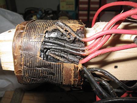
As the layers of wire and paper come off, things
usually turn darker and ever darker! This is because transformers work hottest
at the inside. This picture shows severely carbonized insulation, both the paper
and on the connection wires. Probably the paper slowly carbonized,
becoming slightly conductive, causing further loss, further heating, until
the beast failed for good. This is the problem of paper insulation!
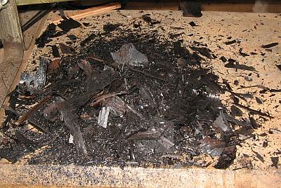 When I was done unwinding this transformer, I found
that even the cardboard winding core was totally carbonized, crumbly and
definitely unusable. I was left with the heap of burned, charcoal-like
insulation shown here, kilometers of thin, crumbly, burned copper wire, burned
pieces of hookup wire, these photos, and a piece of paper where I had written
down wire sizes and turn numbers.
When I was done unwinding this transformer, I found
that even the cardboard winding core was totally carbonized, crumbly and
definitely unusable. I was left with the heap of burned, charcoal-like
insulation shown here, kilometers of thin, crumbly, burned copper wire, burned
pieces of hookup wire, these photos, and a piece of paper where I had written
down wire sizes and turn numbers.
Don't do such a job in your parent's bedroom, because as
you can see, it's messy! Even the kitchen might not be the best place to do it.
Neither mothers nor wifes tend to like this sort of transformer autopsy!
When not even the bobbin is usable, you will need to
make a new one, or find one that fits. I was lucky this time, and found one in
my junk box (aka treasure chest) that just fit this core, and even had side
walls! It's a great thing that core sizes are standarized, even if several
different standards exist...
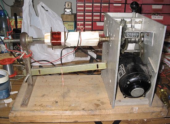
It's probably high time to introduce my transformer
winding machine. Here you can see it in all its glory, somewhat obscured by
the messy background (my workbench). Amateur radio friend Enrique Villanueva,
CE5FSB, gave me this machine when I was still a schoolboy. That was many years
ago, Enrique is no longer in this world, but I remember him every time I
wind a transformer! He was a true gentleman, and always helpful.
This machine is simply a motor and switchable two-speed
gearbox with central neutral position, that drives a
three-pronged thorn, opposed to which is an adjustable centering screw.
It's quite handmade, but does the job well. The fast speed is about 120 rpm, and
the slow one is about 15 rpm.
I added a turns counter to it. It didn't have one when I
got it. This turns counter came from a surplus store, out of a broken gas meter.
It advances 4 counts per revolution, so I coupled it to the machine's drive
shaft via a 4:1 speed reduction, getting exactly one count per turn. To
make this coupling, I made two gears! One was cut from the lid of a coffee
can, has 16 teeth, and is visible in the picture. The other one was made
from a piece of wire, has 4 wire loops acting as teeth, and is hidden in the
photo. It's crude, but was cheap and has worked well for about 30 years now! I
can hardly even try to calculate how many transformers I have wound wit this
machine!
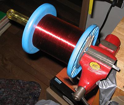
When winding a transformer, you need to have the wire
unwind straight and cleanly from the spool on which it's sold. If you simply
stand the spool on the ground, the wire will twist while unwinding, curl up, and
kink. At that point, you can throw it away and start anew! So, don't. Instead,
you need to fashion some device that allows the spool to rotate, letting the
wire unwind without kinking. This photo shows one of the methods I often use: A
screwdriver, serving as axle, held in a vise.
Sometimes I'm too lazy to set up the vise. In those
cases I simply hold that same screwdriver between my knees while winding the
transformer!
Here you can see the junk box bobbin, made from
Pertinax, mounted on a wooden core in my winding machine, and with part of the
primary winding already wound.
There are several styles for winding transformers. The
highest quality one is to painstakingly lay the windings out in neat, perfect,
orderly layers, with every turn of wire placed precisely next to its neighbor,
in close contact, and never crossing over. Each layer is separated from the next
by a sheet of thin insulation material, cut precisely to the width of the
bobbin, and to such a length that it will overlap a bit. This overlap is placed
at either of the outside sides of the bobbin, not on the sides that will end up
in the core's window. Such a winding is gorgeously beautiful to look at,
produces an excellent fill factor, but is very time consuming to make. I
tend to use that technique when winding few turns of thick wire, but not when
winding many turns of thin wire. One time only I wound a 78,000 turn high
voltage transformer in that way, because no other technique would do, but I
almost turned crazy, and never repeated that feat.
Modern small split bobbin transformers are normally
wound in a very untidy way: The operator at the factory simply lets the machine
run, and fill the bobbin section with wire, letting it build up wherever it
wants to. There are no layers, no insulation between layers, it looks poor,
is less reliable, the fill factor is less good but still acceptable, and
it's fast and cheap to do.
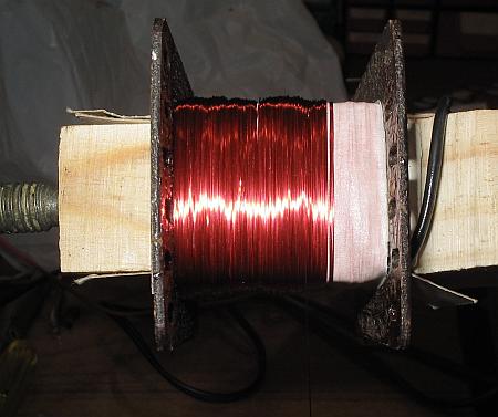
The winding shown in this photo, instead, is a hybrid of
both techniques. The winding is split up into just a few layers, two or
three or so, but each layer is wound thick, with the wire turns actually
building up on each other. I let the machine run and guide the wire to let
it slowly fill the layer from one side to the other (never going forth and back
several times!), letting the windings build up to the desired height, about two
millimeters or six wire diameters in this case. When that ugly layer is
complete, I apply a coating of self adhesive tape as insulation, and then wind
the next layer. It's almost as quick to do as a totally wild winding, but
significantly more reliable.
A word about tapes: Transformer parts stores sell
self-adhesive mylar tape, usually yellow, in several thicknesses and widths.
This is a good material, and you should use it. But I often don't have it on
hand, and use alternative materials. Vinyl insulating tape can be pressed into
service, but isn't great , because it gets very soft when hot, and the wires can
press through it. Much better, even if you don't believe that, is painter's
masking tape! It has just about the optimal elasticity, is thin, cheap, comes in
several widths, holds up well when hot, and looks pretty good on transformers
for antique equipment, on which any plastic tape would look out of place!
Masking tape is what I used for this transformer.
A question many newcomers have is how to handle the ends
and taps of windings. When the wire is rather thick and robust, you can
simply let the end stick out of the bobbin! In that case it's good practice to
protect that wire by a piece of spaghetti (I don't mean an Italian noodle, but a
piece of plastic or fiber hose that looks much like it). It should ideally be
only slightly thicker than the wire. You slip it over the wire, and anchor it in
the winding assembly, with adhesive tape and the pressure of the windings. It
will protect the wire from chafing, and provide additional insulation
at places where the wire might pass very close to other wires or to the
core.
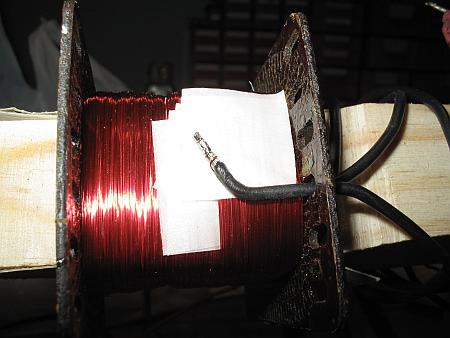
But thin wires should not be treated like that. They are
too fragile, and might very easily break later, forcing you to rip
up and rewind the whole transformer! Instead, you should take some
pigtails of stranded, plastic-insulated wire, strip and tin the ends,
solder the thin enamelled wire to the end of a pigtail, and embed it in the
winding like is shown in this photo. You need to place enough layers of
insulating material both under and over the connection, to make sure that
no sharp tip or edge of the wires may puncture through the insulation. This adds
quite a lot of bulk, so of course these connections must be done on the sides of
the bobbin that will end up outside the core's window!
When you solder these connection, make absolutely sure
that the enameled wire stripped properly in the solder bath. It's very
frustrating to end up with a nice new transformer, that has one winding that
doesn't conduct, because of a badly done connection! In this photo, the first
one and a half loops of the thin enamelled wire around the pigtail didn't strip,
but the other three loops did, so the connection is secure.
One word about safety: Between the primary and secondary
windings, and at any place where there might be high voltage, you need really
good insulation. After connecting this pigtail, which is the end of the primary
winding, I had to apply such safe insulation. When doing it with adhesive tape
on a bobbin like this, it's done by winding several layers of that tape, and
winding it not only all the way to the side walls, but even a bit up
on these walls, forming a kind of cradle bedding for the secondary winding.
You need to get either a perfect seal between the tape and the side walls, or
having so much tape, and the wire moved far enough toward the middle of the
bobbin, that the creepage distance from primary to secondary, around the
insulation, is at least 4 millimeters. This is even a legal safety
requirement!
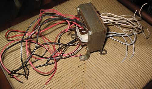 After winding the two secondaries with their lots
of taps, and re-assembling the core, the finished transformer looked like
this, in all the glory of its dozens of connecting wires! In this Heathkit
tube tester, the wires connect directly to the circuit. In other cases, these
wires would be neatly dressed and soldered to terminal strips, which are
either embedded in the outer layers of insulation in the winding assembly,
or bolted to the core.
After winding the two secondaries with their lots
of taps, and re-assembling the core, the finished transformer looked like
this, in all the glory of its dozens of connecting wires! In this Heathkit
tube tester, the wires connect directly to the circuit. In other cases, these
wires would be neatly dressed and soldered to terminal strips, which are
either embedded in the outer layers of insulation in the winding assembly,
or bolted to the core.
 A
winding machine with turns counter is a great tool, but it's not absolutely
necessary. Transformers can be wound with much simpler tools too. And despite
having my machine, sometimes I have to wind transformers that are larger than
what the machine can handle!
A
winding machine with turns counter is a great tool, but it's not absolutely
necessary. Transformers can be wound with much simpler tools too. And despite
having my machine, sometimes I have to wind transformers that are larger than
what the machine can handle!
Such was the case in 2008, when I had to build two
transformers for 10kVA each, starting from scratch. These are the transformers I
chose as an example to put into the spreadsheet before uploading it to this
page! In the sheet, the primary voltage is 230V and the secondary is 2000V. In
truth, one of the transformers works in this way, while the other is opposite,
the 2000V winding serving as primary. In the following discussion, I will use
"primary" to refer to the high voltage winding, regardless of how the
transformer will be used later.
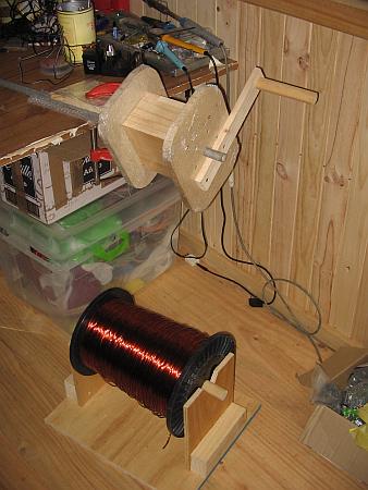
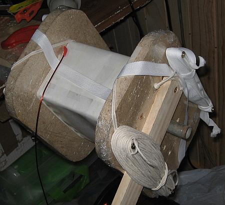
I built the simple but effective setup shown in the
photo. A big wooden bobbin was made, with dimensions such that the complete
winding package for the transformer would precisely fit inside. Note that this
bobbin is just the support for winding! It will be removed before final
assembly of the transformer. For this purpose, it's held together by
screws, and the wooden pieces on the inside are designed so that they can be
easily removed from the finished coil assembly. This big wooden bobbin got
fitted with a hand crank, and mounted on a steel tube serving as axle, which was
clamped to the workbench.
Each wooden piece of the bobbin was separately wrapped
in kitchen wrap (saran wrap, Sichtfolie) before assembling the bobbin. This
assures it can be disassembled after varnishing the winding assembly,
without the wood sticking to the coil assembly!
The spools of wire for these big transformers weigh
30 kg for the secondary, and 25kg for the primary. So I made a simple but
sturdy support structure for them and placed it at the work site.
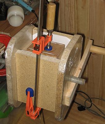
Instead of a complete bobbin with side walls, I chose to
employ only a basic bobbin, made from a sheet of 1.5mm thick Pressspan (I
couldn't obtain a material strong enough with a better temperature rating).
The Pressspan was cut to size, half-depht cuts were made with the knife at the
bending lines, then it was bent around the wooden bobbin. The overlapping side
was smeared with epoxy glue, and the whole thing was compressed with wooden
boards and clamps like shown here, to get it nice and straight.
Since the Pressspan might carbonize and become slightly
conductive at high temperature, I wound two layers of high temperature NMN
laminate over this core, to insure permanent safe insulation between the winding
and the core. It's temporarlily held in place with plain office type adhesive
tape, but this tape is later removed when winding the wire, to keep it from
carbonizing and possibly causing trouble.
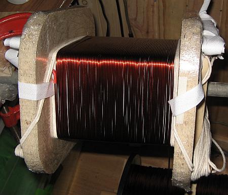
This transformer has sufficiently few turns and thick
wire to wind it in orderly layers, separated by insulating sheets. To keep the
whole thing from falling apart, I bound the layers together with cotton straps,
and to make sure the wire turns don't get closer to the edge of the bobbin than
5mm or so, I wound cotton ropes at the edges, used as spacers. These ropes will
be removed later.
The photo shows the assembly, ready to start winding. A
double rope makes one turn on each side of the bobbin, enough spare rope for the
successive turns is coiled up on screws driven into the bobbin, and
the cotton straps are installed and coiled up too. The wire end, protected by a
piece of high temperature red fiber spaghetti, is anchored in a hole drilled
into the wooden bobbin. Time to start winding!
 The first layer has to be wound very
carefully, pushing each winding into tight contact with the previous one. When
that first layer is complete, be sure to count the turns to make sure you
actually got as many turns as you calculated! Otherwise, you need to compress
the winding a bit more, and then add the remaining turns.
The first layer has to be wound very
carefully, pushing each winding into tight contact with the previous one. When
that first layer is complete, be sure to count the turns to make sure you
actually got as many turns as you calculated! Otherwise, you need to compress
the winding a bit more, and then add the remaining turns.
When not using a turns counter, such as in this case, a
good thing to do is to wind a full layer, then count the turns, and write it
down. Don't forget! Otherwise it's just too easy to loose count of the layers!
That sounds stupid, but it's very real. A good way to count the turns is to
lightly draw a pointy, non-scratching object (plastic or wood) over the wire
turns, and count the clicks as you feel them. Counting by sight tends to be
confusing.
Since the wire isn't ever perfectly straight, it's
impossible to completely eliminate air between the turns. That's why you have to
consider a safety factor when calculating how many turns you can fit in each
layer!
The next layers instead are easier to wind, because the
wire will embed itself slightly in the depressions between two turns of the
previous layer, automatically assuming the correct spacing. Note that
this produces either winding layers which alternatingly have one more or
one less turn, or else the windings with the same number of turns in each are
alternately offset sideward by one half wire diameter, respective to each other.
You need to consider this when designing the transformer, when you intend
to do a neat, tight winding like this.
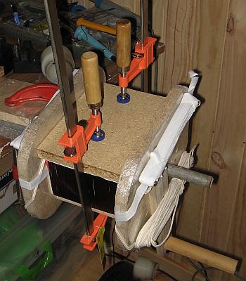
After each layer, the wire is pressed flat, using boards
and clamps, on the sides of the bobbin that will end up inside the core's
window. This further helps to actually make the winding fit. It doesn't matter
at all if the windings bulge out a bit on the other two sides, because these
will end up outside the core, where space is plentiful.
If you do this, be careful not to damage the wire's
insulation. It's quite tough, but not infinitely so. The boards should have a
smooth and not too hard surface. I used a thick paper as cushion between the
chipboard and the wire.
After winding and compressing a layer, a single layer of
insulating material (NMN laminate in this transformer) is wound, overlapping it
a bit on one side that won't be inside the core window. Then the four ends of
the cotton straps are crossed over, pulled tight, and reattached to the bobbin,
and the cotton ropes are wound another turn, taking care to avoid tangling the
straps with the ropes! The straps will remain in the transformer, while the
ropes will be removed. So the straps should hold just the wire and insulation
sheets, but not the ropes.
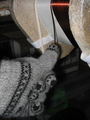 If you simply let the wire unwind from the
spool and wind it on your transformer, it will get a bow shape instead of lying
flat, and have so much air below it in the center region of each bobbin side,
that later when compressing the layer you would get excessive bulging on the
other sides. To prevent this, the wire gets a pre-bend in the opposite sense
while winding, by guiding it with the thumb like shown here. I used a woolen
glove for this, because the wire has to be kept pretty tight, is quite stiff,
and it would wear through my skin, despite being quite smooth!
If you simply let the wire unwind from the
spool and wind it on your transformer, it will get a bow shape instead of lying
flat, and have so much air below it in the center region of each bobbin side,
that later when compressing the layer you would get excessive bulging on the
other sides. To prevent this, the wire gets a pre-bend in the opposite sense
while winding, by guiding it with the thumb like shown here. I used a woolen
glove for this, because the wire has to be kept pretty tight, is quite stiff,
and it would wear through my skin, despite being quite smooth!
This photo was shot during the winding of an
intermediate layer of the primary.
The wire and the cotton ropes are placed between
the ends of the insulation sheet, for the transition from one layer to the next.
Said in a different way, the insulation sheets are simply wound into the coil of
wire and rope.
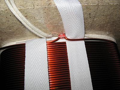
Here you can see how a center tap is made. The winding
was arranged in an even number of layers, so that the center point ends up at
the transition from one layer to the next. At this point, the wire was brought
out and back in through a single hole, and protected with spaghetti. The spacing
ropes were also brought out and back in through two holes, to keep them from
interfering with the wire tap. Finally, the cotton straps are threaded so that
they will hold both wire ends in place.
After this, the insulation layer can be wound, and then
the ropes and the wire for the next layer.
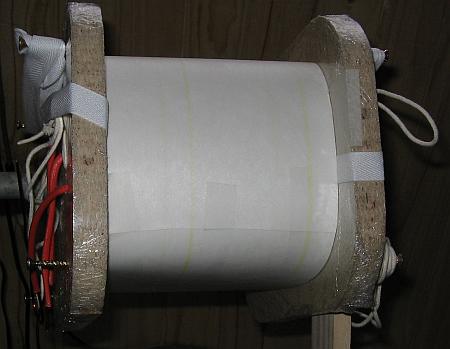
After winding the last layer of the primary, the spacing
rope is anchored in a hole in the bobbin. The end of the wire is treated just
like the beginning of it, and brought out through a hole too. I drilled all
these holes where needed, while winding.
Then several layers of insulating material are wound,
since the voltage between primary and secondary can reach 10kV or more during a
nearby lightning strike! These transformers were built to send power over a 600
meter long outdoor transmission line, in a mountainous and lightning-prone
area.
Since the secondary winding uses much thicker wire, the
spacing rope needs to be thicker too. I used one strand of thick rope for the
secondary, and two strands of thinner rope for the primary. As a result, both
windings are spaced about the same 5mm from the sides.
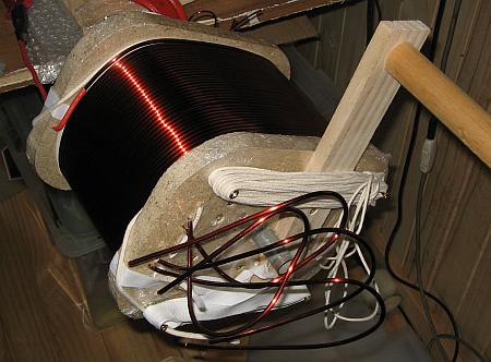
The secondary is wound just like the primary. In this
case it was a little more complicate, because I actually wound two secondaries,
each of them having a wire half the cross section calculated in the sheet. On
top of that, each of the secondaries is center-tapped too.This allows me to do
several clever things with my transformers, and as a bonus lets me wind with a
thinner, more manageable wire. This is #7, still stiff enough!
The photo shows the completed secondary, before applying
the final layers of insulation. You can see the spacing ropes, and how the
cotton strap will hold the last turn.
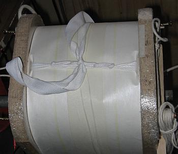
The spacing ropes are pulled through holes and secured,
several layers of insulation are wound, the final layer is secured with a loop
of masking tape, and then the cotton straps are pulled tight one last time, and
knotted together using a special pulling knot, the same sort truckers like
to tie down their cargo. If you don't know how to tie such a knot, ask a
trucker, a sailor or a boy scout.
At this point, the winding assembly is ready to remove
part of the wooden bobbin, and start the varnish impregnation process.
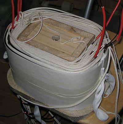
Removing one of the side walls of the wooden bobbin
reveals not only the structure of the inner part of the wooden bobbin, designed
for strength and easy disassembly, but also you can see the spacing ropes
partially falling out, leaving the insulation protruding nicely between the
turns of wire. This produces plenty creepage distance for safe operation!
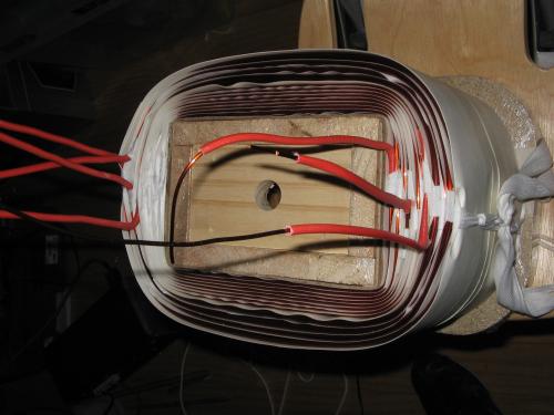
After removing all those ropes, the winding assembly
looks like this. Note how the wires are nicely tucked in between the insulation
layers.
While the cotton straps do a great job holding the end
turns of each layer in place, preventing them from falling out and the whole
thing springing open, this assembly is still far too weak to be used like this.
Considerable forces act on wires of big transformers. They need to be secured
very well.
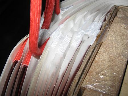
And a further closeup showing how the straps hold the
wires, and bend the insulation, always maintaining a safe creepage distance.
In this photo you can also see the overlap of the
Pressspan bobbin, complete with some epoxy glue that seeped out before setting.
Since the bobbin was made 2mm shorter than the core's window length, such
seepage and similar imperfections cause no trouble.
Without removing the other remaining parts of the wooden
bobbin, I soaked the entire winding assembly in impregnation varnish. I
poured the varnish in from the top, until it flowed out profusely from the
bottom. Then I let the assembly soak, let the excess drip off, and let it dry
somewhat on the surface.
But this is an oven-drying varnish, so it needs to be
heated, or it will never dry. I do have a thermostatically controlled oven - but
not large enough to fit a winding assembly of this size! So I applied enough DC
current to the primary winding to slowly heat up the whole thing to a
temperature high enough to dry the varnish.
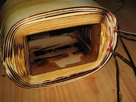
Every transformer varnish has a recommended drying
temperature. To get it right, I occassionally removed the power supply, and
measured the resistance of the primary winding. Comparing to its resistance when
cold, and considering the thermal coefficient of the resistance of copper,
it's easy to calculate the internal temperature! Then I adjusted the DC current
to keep the temperature just right.
I removed the other wooden bobbin side, and the spacing
ropes on that side, when the exposed side of the assembly seemed to be dry. The
newly exposed side was still fresh, so drying continued with the assembly
supported only by the wooden parts in the center.
When the varnish stopped smelling, signalling that it
was dry, I removed all of the remaining wooden parts. This was quite easy,
thanks to the kitchen wrap, which stayed partially adhered to the Pressspan
core. In this photo you can see that. The brownish color is that of the varnish,
while the near black sections inside the assembly are partially carbonized
kitchen wrap. This stuff doesn't endure the temperature the varnish needs to
dry! But no harm was done, except to the wrap, which is of
course irrelevant.
At this point, the winding assembly has a monolithic
feel, with everything firmly glued together by the varnish. It could actually be
used without further work, but the edges of the thin insulation material are
quite fragile. Any object striking them could bend or even break them,
compromising the creepage distance and thus the safety of the transformer! 2000
volts at 10 kilowatts is not something to take chances with.
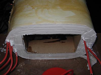 So I filled these areas with silicone caulk.
This material is available, inexpensive, easy to work with, tixotropic,
permanent, an excellent insulator, and endures very high temperature. In short,
it's a nearly ideal material for this task! There is only one point to watch: Be
sure to use the neutral curing type, not the more common, acid curing one! The
last thing you want to do is releasing highly corrosive acetic acid into your
new transformer!
So I filled these areas with silicone caulk.
This material is available, inexpensive, easy to work with, tixotropic,
permanent, an excellent insulator, and endures very high temperature. In short,
it's a nearly ideal material for this task! There is only one point to watch: Be
sure to use the neutral curing type, not the more common, acid curing one! The
last thing you want to do is releasing highly corrosive acetic acid into your
new transformer!
The color of the silicone is your (or in this case, my!)
choice.
I didn't do a particularly neat caulking job, but the
point was to get the edges sealed and protected, not to do a work of art.
The winding assembly is now ready!
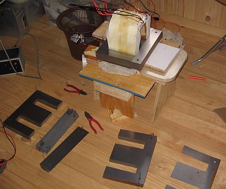
The next step is assembling the core. I usually do this
in the same way for every transformer: I place the winding assembly on one side,
then I start inserting E laminations from alternating sides. Distributed
throughout the core, I occassionally insert two consecutive E's from the same
side. When almost all E's have been inserted, things tend to get pretty tight,
and forcing additional E's in between the last one and the winding
assembly, can lead to damage to the latter!
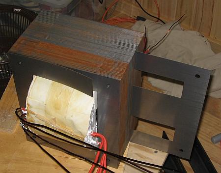 This is where the E pairs inserted from the same
side come into play: They form excellent guides for inserting a third E
between each two neighboring E's, even using a wooden block as a hammer to drive
them in, if necessary! This is the best trick I have found to obtain a nice,
tightly compressed lamination stack.
This is where the E pairs inserted from the same
side come into play: They form excellent guides for inserting a third E
between each two neighboring E's, even using a wooden block as a hammer to drive
them in, if necessary! This is the best trick I have found to obtain a nice,
tightly compressed lamination stack.
After all E's have been inserted, the I's are slid into
the voids. After that, two wooden blocks and a big hammer are used to knock all
the laminations into their correct positions, aligning them with each other, and
specially, align the screw holes of all the laminations!
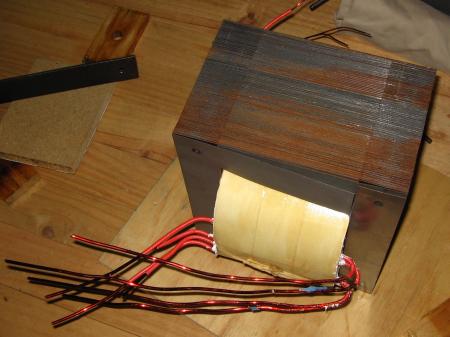
At this point, the transformer is functional, and you
can hook it up and try it, if you want. But it will hum like crazy, because all
those loose steel laminations will magnetically repel each other at twice the
line frequency rate, and vibrate. The core needs to be tightly compressed to
stop all that noise. The performance will also improve when the core is
correctly compressed.
In small transformers this is done with clamps. But big
ones, like this, use bolts. Often you won't find real bolts long enough and thin
enough, though! In those cases, buy some threaded stock, which is sold in great
lengths, cut it to size (a Dremel tool with a heavy duty cutoff disk does this
very nicely!), and use it with washers and nuts on each end.
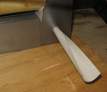
In large transformers, these bolts sometimes have enough
shorting action to cause significant additional loss and heating! For this
reason it's a good idea to insulate the bolts from the core. You can use
tubing for that purpose, or like I did here, slide in a sheet of NMN laminate
(or plain paper) rolled into a tube.
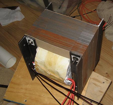
Installing the bolts just on the core leaves you with an
unevenly compressed lamination stack, and what's more important, with nothing to
mount the transformer! For that reason usually some angle stock is used . It
distributes the force over much of the core, and provides convenient surfaces to
drill mounting holes into.
Some transformers use formed caps instead, or complete
steel frames.
Note the insulation sheets under the washers of the
bolts! Depending on the specific transformer, they might make any difference,
from barely noticeable to dramatic!
At this point, the transformer is truly ready for
trying. If it still hums, you can try tightening the bolts even further, and
inserting wooden or plastic wedge pairs between the winding assembly and the
core center leg, to compress the latter. If even this fails, which is often the
case, then you have no better option than once again getting your varnish can,
and soak the core in varnish! You can loosen the bolts, let varnish
flow into every space, then tighten the bolts again and warm up the
whole transformer by applying a suitable amount of DC for at least a full
day. I have yet to see a transformer that still hummed after that
treatment!
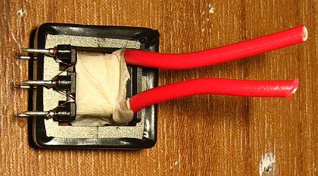 Depending on the application, different
things can be done with the connections. If they are made of flexible wire, they
might be directly wired into the circuit. In small transformers, often plastic
bobbins with pins are used, and the windings are connected to these
pins, like shown here, and then the whole transformer is soldered to a
printed circuit board. The example shown here is a current sensing transformer,
which also has a one-turn, high current winding, which is brought out
separately from the bobbin pins.
Depending on the application, different
things can be done with the connections. If they are made of flexible wire, they
might be directly wired into the circuit. In small transformers, often plastic
bobbins with pins are used, and the windings are connected to these
pins, like shown here, and then the whole transformer is soldered to a
printed circuit board. The example shown here is a current sensing transformer,
which also has a one-turn, high current winding, which is brought out
separately from the bobbin pins.
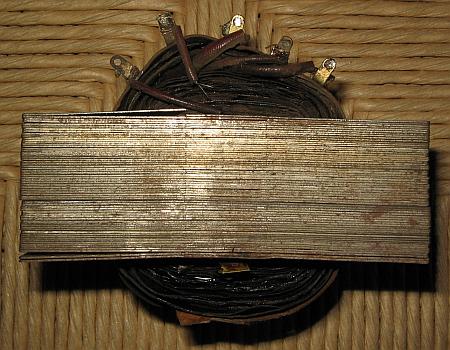 Often terminal strips are attached to the winding
assembly, and the windings are connected there. But in larger transformers, the
most common practice is bolting terminal blocks to the transformer, and
connecting the wires there. I did this with my large transformers, leading to
the final product shown in the very first photo of this web page. That
system is more solid and reliable then most others, and allows repeated
solderless disconnection and reconnection, which I need a few times per year to
reconfigure my transformers for different conditions of usage.
Often terminal strips are attached to the winding
assembly, and the windings are connected there. But in larger transformers, the
most common practice is bolting terminal blocks to the transformer, and
connecting the wires there. I did this with my large transformers, leading to
the final product shown in the very first photo of this web page. That
system is more solid and reliable then most others, and allows repeated
solderless disconnection and reconnection, which I need a few times per year to
reconfigure my transformers for different conditions of usage.
Some people wonder whether they should try winding their
own transformers, or if they should instead shell out big $$$ to have the job
done by a professional winding shop. I can only tell you one thing: If you had
the patience to read this long web page from start to end, then you most certainly also have the patience
required for winding your own transformers!!!
Back to homo ludens electronicus.