Making a HV transformer
for the Tektronix 310 scope
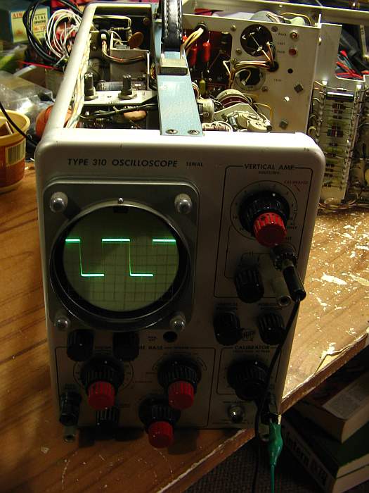
Recently I was given a Tektronix 310 oscilloscope, which was missing
several parts. Among them the HV transformer. Here is a quick photo
sequence about making that transformer.
At the start I didn't even know how that transformer looked, let alone
its design. Several people provided information, which combined with
the scope's manual to allow designing a replacement.
The original ferrite core is a quite short and fat double E core with
octogonal center leg. In place of that one, I chose the power
supply transformer from a junked TV set dating to the early
1990s, which has a round center leg of roughly the same cross section
as the original core, but allows a much longer coil assembly. I put
this transformer in the oven to soften the glue holding it together.
Then I could easily separate the core halves, and then unwind it,
recovering the intact bobbin.
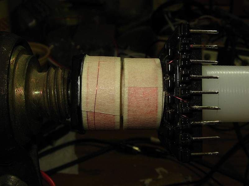
Okay, let's start. I wound the primary first, using #33
wire, 154 turns for the main winding and 77 turns
for the feedback section, in three layers, leaving a generous unused
margin on each side, and using painter's masking tape for
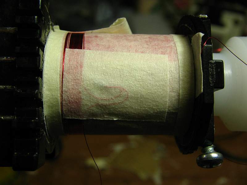
insulation and to make up the sides. This photo shows the completed
primary.
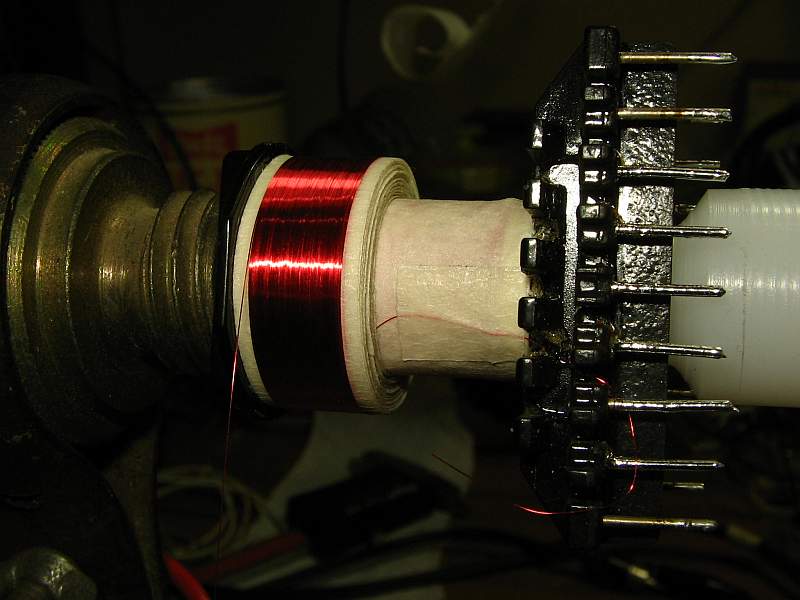
Then I wound the two high voltage secondaries, in what I call "thick
layers", which are a type of scrambled winding, but instead of building
it up evenly from top to bottom, it's built up
evenly from one side to the other. That requires winding on a conical
face of the winding, which takes some care. But such a winding is very
quick to do, is space-saving because it doesn't need any insulation
within it, and it has much lower capacitance than a layered winding. I
have made many such thick layer windings with good results, but making
one for close to 2kV with only 20mm length, like here, is critical at
best.
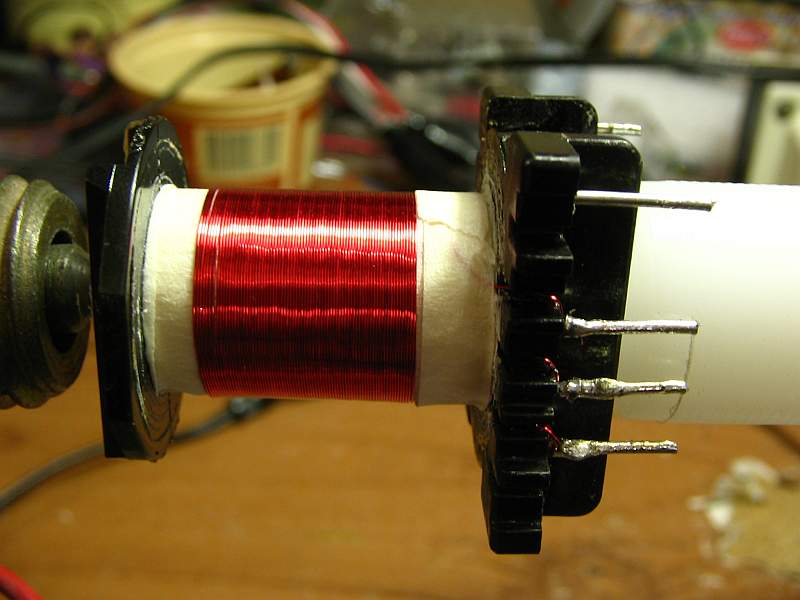
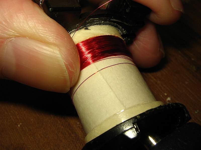
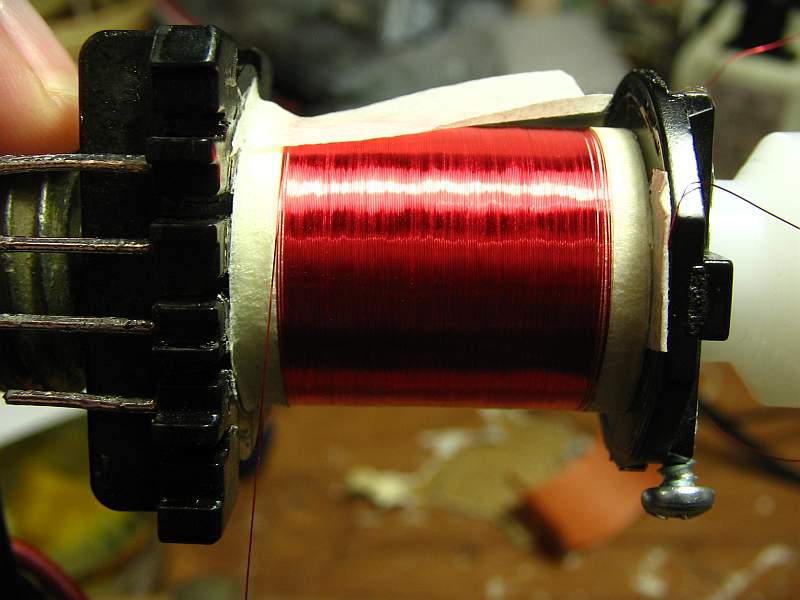
The HV secondaries have 1269 and 1346 turns of #39 wire.
Here you can see the first secondary completed. It looks like a plain
scrambled winding , but all cold end turns are on the left, and all hot
end ones on the right.
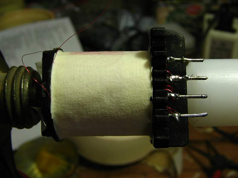
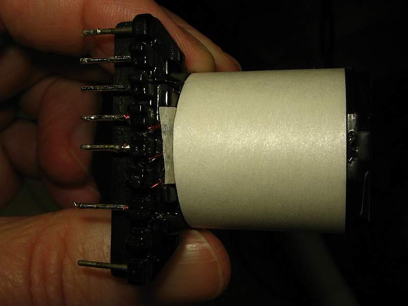
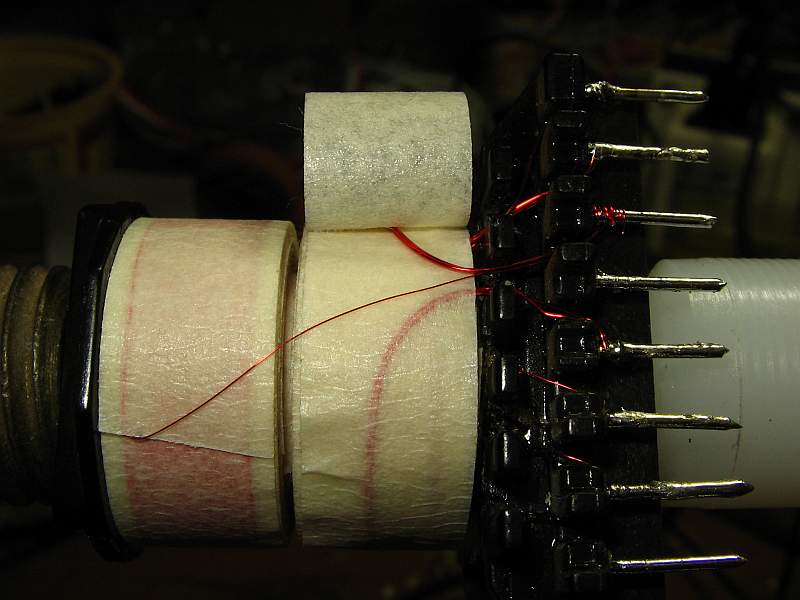
I brough out the cold end connections by stranded wires, to avoid
having high voltage between the pins of the bobbin, which are a tad
close together for 2kV. Here you can see how those connections are
made. The hook-shaped ends of the stranded wires prevent damage to the
fragile #39 wire if the stranded wire is twisted and pulled.
On the right side you can see the bobbin pins having some relatively
thick wires connected. These are the filament windings, one turn of
bifiliar #30 for each. A single strand of #27 would have been
as good, but more bulky - and I didn't have any solderable #27 at hand!
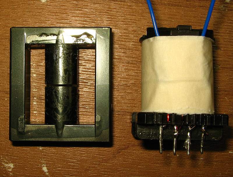
This shows the core and the completed coil assembly. The core center
leg is 13mm diameter. The external core dimensions are 40x45x13mm. The
air gap is 0.88mm wide, which is pretty large for this transformer. but
still acceptable. It will result in a slightly higher than nominal
oscillation frequency.
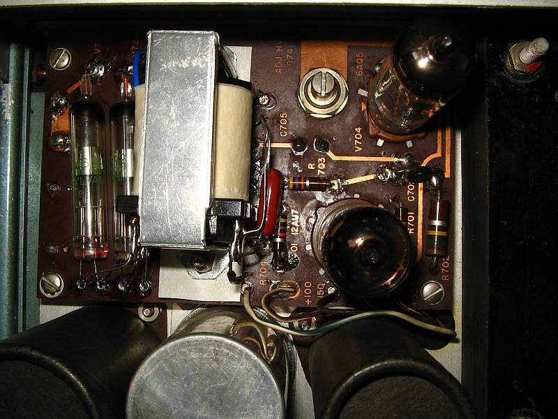
The new transformer installed on the 310's HV supply board. I fashioned
a simple bracked from aluminium sheet for mounting the transformer. It
looks a bit strange with the bobbin pins poking into the air, but if it
works, so be it!
The problem is that it didn't work. At least not for long! After a
total of about two minutes working nicely, oscillating at roughly 35kHz
and producing what seemed to be a normal HV output, it started
sizzling, and the HV broke down. That means arcing inside the
transformer.
I tore down and unwound the secondaries, searching for the cause of the
problem. And I found it in the Hv winding I had wound first: While
winding the thick layer, one turn had slid away from its righful place,
and hed been pushed further and further away by the new turns being
wound over it. Finally it ended up several millimeters down the coil,
in contact with wire turns that carried a very different potential. At
the place where the underlying insulation sheet pressed this turn up
against the others, thus slightly compressing the enamel, it broke down
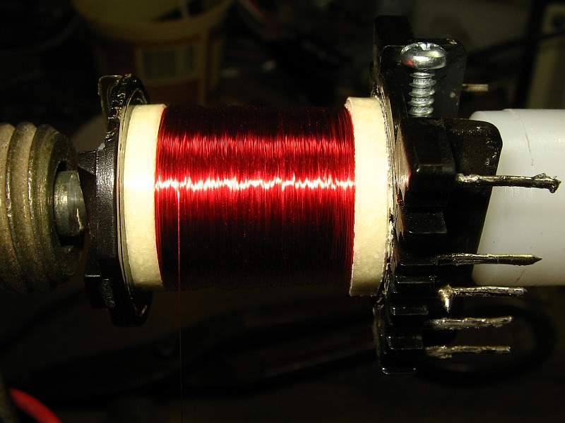
and a short between turns resulted. Right in the middle of this photo
is the failure point.
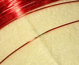
And if you couldn't see it, here is a close-up, clearly showing the
burned enamel. Don't worry about the shiny place left to it, that's
just a reflection of the lamp.
I could have tried to just wind the secondaries again, with the same
thick layer technique, but with more caution to avoid turns slipping
out of place, and hopefully more luck. Instead I decided to
try a conventional layered winding. Each secondary would take 8 layers.
Interlayer insulation would be provided by a single layer of masking
tape.
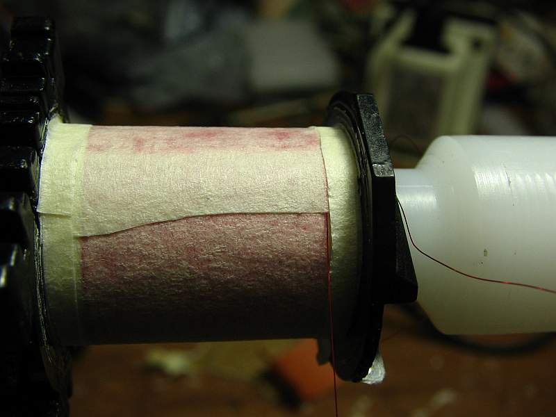
This photo was made in the middle of the winding process, showing such
an insulation layer with a small overlap, a 3mm wide strip of tape on
each side and the wire coming out between the tapes, ready to start
winding the next layer.
And this shos the layer complete. It's not perfect, specially at the
start and end, but decent. The loose piece of tape on top is used to
keep the wire from unwinding while I shoot the photo.
Accidents do happen. When I was three quarters through, the wire
snapped and broke. Not wanting to undo the whole winding and make it
anew, I cut out all the wire that could have stretched, then soldered
the wire together, and embedded it between several layers of tape, as
shown here. Such a patch needs much more insulation than what goes
between layers of wire, because the solder joint doesn't have enamel
around it, and does have sharp points, so that it's much more prone to
corona effect than the undamaged wire.
For the same reason, I used a relatively thick blob of solder, so the
sharp points and edges would be minimized.
This is also a good time to mention that all those things that add bulk
to the winding, such as overlap of insulation layers, embedding joints,
wires running across the winding sense, etc, are ALWAYS made at those
sections of the coil that will end up outside the core! So the final
coil assembly is somewhat oval rather than perfectly round, with the
shortest diameter at the place that goes into the core.
In this version of the transformer I started winding one HV secondary
at the cold end, completing it in the middle of the eight layer. I made
the single turn filament winding right there, then applied two layers
of masking tape, then wound the single turn filament winding of the
other secondary, and then started the second HV winding, still in that
same layer. All high voltage stuff is embedded inside the secondary
windings, and comes out at the bobbin pins. Instead the cold ends come
out as wires, and both the outside layer, and the bottom layer close to
the primary, are at low voltage.
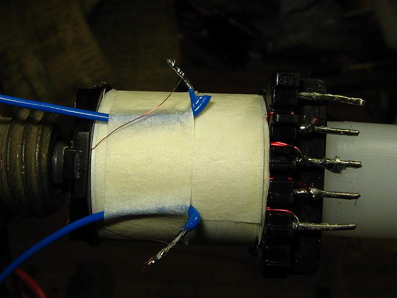
The winding is now complete. The two cold end wires are poking out on
the left, ready to be soldered to stranded wire pigtails.
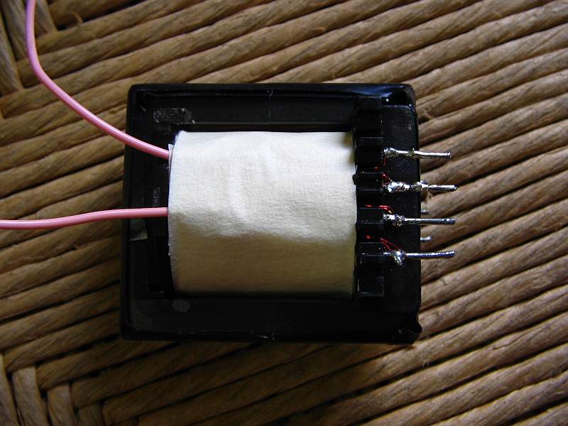
Version #2 of the transformer is ready. Externally, the only thing that
changed is the color of the wire pigtail insulation. Not that I would
love pink, but I didn't like that the blue wire insulation melts so
fast while soldering!
And here it comes: The result!
But there is still some work to do. The new transformer has too much
capacitance. As a result it warms up quickly, and the HV regulation
circuit then gets out of range, the HV starts to drop, and the trace
gets weak. When cold, it operates just at the limit. So I will have to
do a version #3 of this transformer. I think it will be OK
to wind the two secondaries using half the bobbin with each,
so that each secondary uses 16 layers of half the width, resulting in
one quarter as much capacitance as they have now. Another option would
be a bifiliar wind, both secondaries at the same time, as was
apparently done in the original transformer. That would result in the
same reduction of total shunting capacitance, but with lots of
capacitance between the two HV windings, which is probably acceptable.
But given the added difficulty in making bifiliar windings, I think I
will make side-by-side windings.
Also the scope still needs several other repairs, but nothing too
terrible.
Transformer #3:
Finally I wound it! I reduced the
turns number to raise the volts per turn to 1.3 rms. So, what I wound
this time is:
Primary: 115 turns for the main winding, plus 57 turns for
the feedback winding, #33 wire, in two layers.
Secondaries: 975 turns for the cathode supply, 1050 turns for the grid
bias, #39 wire. I wound these side-by-side, in 13 layers each.
The insulation between layers was two turns of masking tape, which is
0.08mm thick. This was done to reduce interlayer capacitance as much as
possible.
The filament windings are 1 turn of bifiliar #30 wires, for each
filament.
This photo shows the completed grid supply secondary, wound over the
left side of the primary.
And now the cathode supply secondary is ready too.
The two filament windings are wound on top of the cathode secondary,
because it has one layer less than the other winding, so there is
more room. This photo shows the grid supply filament winding, and the
hot side connection of the grid secondary. The other filament winding
is faintly visible through the tape.
Note air spaces between both secondaries, and between the cathode
secondary and the wires coming out of the windings. Corona is less
likely to form around wires separated by air, then if they have lots of
dielectric material in between, and
some air around the wires!
Then the whole winding assembly was wrapped in NMN insulation material:
This transformer is working fine, with the voltages in the oscillator
section being quite normal. There is just one thing I would change: The
grid secondary turned out to deliver about 3% too much voltage, so that
the intensity control needs to be turned pretty far up for the trace to
start appearing. So, if you want to copy this transformer, I would
suggest just 1020 turns for the grid secondary, instead of the 1050
turns I used.
I was too lazy to take out the transformer again to remove those 30
turns, even if it would be quite easy. Instead I added a dropping
resistor to bring the bias voltage to the correct value.
The air gap of the core is now 0.4mm. I sanded down the core side legs,
using a belt sander, to achieve this value.
I think this pretty much completes the job!
Back to the homo
ludens electronicus
page.