Spot welder using a microwave oven transformer
Building spot welders out of old microwave oven transformers
has become kind of a sport. Lots of people are doing it, since there
are so many old MOTs out there, just asking to be put to good use!
One can't expect stellar power and performance from one of
these, given that for a good spot weld in thick material one needs a
peak power of tens of kilowatts, which a MOT can't deliver. But for
small jobs, such as welding tabs to battery cells, they work
great.
A
long time ago I joined this sport, and put together a simple MOT spot
welder, just for that task. I never put it in a box, so it's not a
finished project, but since it works well, I now decided it to put it
on my website anyway.
Any usable spot welder needs an adjustable
timer, that controls the
duration of the current pulse. The idea of spot welding is to compress
the two parts to be welded between two electrodes of much higher
electrical conductivity, then apply a brief, intense current pulse that
melts a small spot of metal where the two pieces meet, and then keep
the pressure while that metal again solidifies, cleanly welding the two
parts together. The timing needs to be just right. So any attempt to
work
without a timer will result in either burned metals, holes, or
something more
akin to arc welding than spot welding.
Larger spot welders also
control the amount of current, but a MOT spot welder is always a little
too weak anyway, so there is no point in further reducing the current.
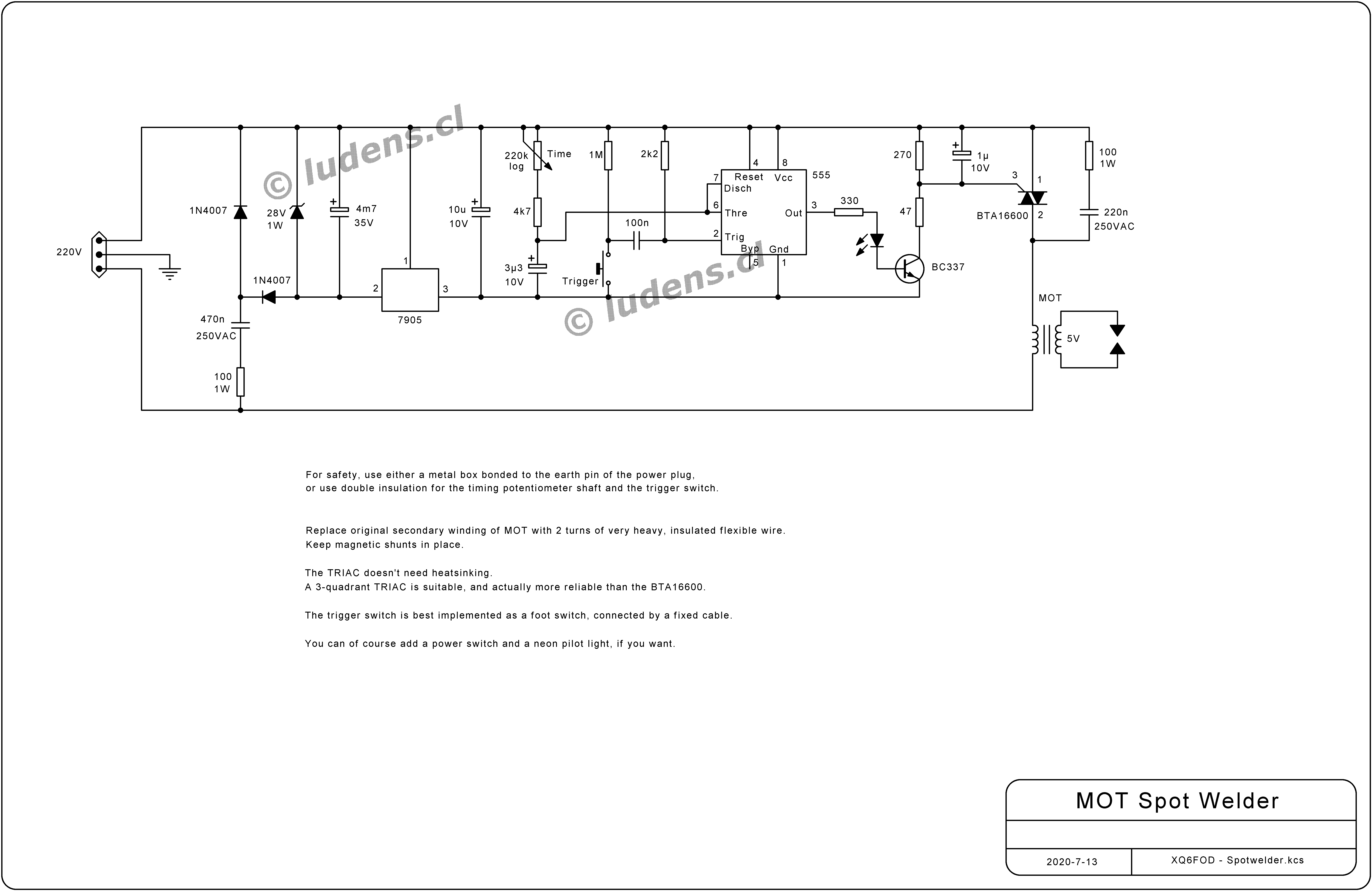
In
my design there is no current control, and the timing is implemented
simply in a 555 timer IC in monostable configuration. The timing
components are selected to give a pulse adjustable from roughly one
single cycle of the AC grid, to nearly one second. This pulse is used
to control a TRIAC, which is fitted with a snubber network to prevent
problems caused by the highly inductive load presented by the MOT.
The
timer circuit is powered directly from the grid by a cheap reactance
supply, saving an additional small power transformer. This supply can
provide only about 15mA, which is insufficient for triggering a TRIAC,
and for that reason a relatively large filter capacitor is used, which
provides enough reserve to deliver about 80mA of trigger current to the
TRIAC for the duration of a welding pulse.
TRIACs work fine when
the gate trigger voltage is the same polarity as the load, and they
also work fine when the gate trigger voltage is always negative.
Instead they are less good, and some don't even work at all, when
the gate trigger voltage is positive and the load is negative. So, my
circuit triggers the TRIAC with negative voltage, and for that purpose
the timer circuit is powered from -5V, provided by a negative
voltage regulator, the 7905. This circuit might look a little confusing
to people accustomed to always having a negative ground, and regulating
the positive line, but there is nothing wrong with it! It's just a
little upside down...
The 7905 can of course be any
brand, which determines the letters in front: LM7905, UA7905,
L7905, MC7905, and so on. The pinout stated is for a TO-220
package. Likewise, the 555 timer can be any brand and letters, like
NE555, LM555 and others. CMOS versions of the 555 should work too, as
long as it is one that has enough driving capability. Not all CMOS
versions do. If in doubt, better use a basic 555.
I used a
BTA16600 TRIAC, simply because I had some in my treasure chest, and it
works fine, but this isn't the optimal kind of TRIAC for this task.
It's a 4-quadrant TRIAC, and these are often a little sensitive to
self-triggering with inductive loads. So, if you have to buy the TRIAC
for this project anyway, it would be best to get a 3-quadrant TRIAC
instead, such as the T1635-8T. Although these are advertised as
"snubberless", do keep the snubber in this application!
Neither
the TRIAC nor the voltage regulator need a heatsink, since the
welding pulses are short, and typically with long pauses in between.
Instead of the BC337, any small NPN transistor that can comfortable handle at least 100mA should work fine.
The
470nF and 220nF capacitors need to be rated for direct AC line
connection. The kind that has a collection of safety agency logos
printed on them, commonly known as X capacitors.
And the
electrolytic capacitor marked "4m7" is 4.7 millifarad, which is
4700 microfarad! Don't get that wrong. I often wonder why
electronicans love talking about thousands of microfarads, while they
don't usually talk about millions of milliohms, or anything like
that...
The potentiometer should be a logarhythmic one,
if you can find it, to give a nice spread of time values. If you use a
linear one instead, the shortest pulse lengths might be hard to
set.
The trigger switch is best implemented as a foot switch,
so you can keep both hands free to hold the electrodes, and the parts
to be welded. Anyway one typically needs at least three hands, if not
four, when spot-welding without a proper jig, clamp or other
device! So don't plan on using your fifth hand for the trigger switch...
The
MOT is prepared for this use by cutting out the high voltage winding
and the filament winding, and keeping in place the primary winding and
the magnetic shunts. Then the freed window space is used to wind two
turns of the absolutely thickest, stranded copper wire you can get
through. The wire ends should not be too long, and end in massive
copper electrodes, that have dull conical tips of about 1 to 2mm
diameter, depending on what you want to weld, and the power of your
MOT. Those copper electrodes should be at least 6mm or so in diameter,
preferably something like 10 to 12mm. We are talking about a current
like 500A, at just a few volt, so the total circuit impedance must
not be higher than a few milliohm, and we want as much as possible of
that to be the resistance of the material we want to weld, NOT the
electrodes nor the wiring!
The whole spot welder should be built
into a metal box, grounded to the earth contact of the power
plug. The entire circuit is at line potential, so it should be
protected from accidental touch. Don't be as lazy as I am! I never
put mine into a box, as I should, since I use it only very
rarely. I just built the timer on a perfboard, and the power part in
self-supported 3D style, and I hold both welding
electrodes in my hands. So please excuse me for not wanting to show you
photos of my contraption, but at least you can see the schematic
diagram, which looks a lot nicer than my practical implementation of
it! You can even click it to get a high resolution version, which
is good for printing.
Back to homo ludens
electronicus.