160V 3A DC motor power supply
 Several
years ago I purchased a small lathe. It's one of my nicest toys. This lathe came with a plain and simple
single-phase 0.5 HP induction motor, Chinese-made, which took a
tremendous current pulse to start up, and also caused quite a lot of
vibration. It worked for a few years, then one day it smoked off.
Instead of repairing it, I replaced it by a small permanent magnet DC
servomotor, made by Minertia, which I had gotten as a gift. It had been
used in some large line printer. This motor worked fine, free of
vibration, but it wasn't powerful enough for my larger jobs - it was
rated at just 60 watts or so!
Several
years ago I purchased a small lathe. It's one of my nicest toys. This lathe came with a plain and simple
single-phase 0.5 HP induction motor, Chinese-made, which took a
tremendous current pulse to start up, and also caused quite a lot of
vibration. It worked for a few years, then one day it smoked off.
Instead of repairing it, I replaced it by a small permanent magnet DC
servomotor, made by Minertia, which I had gotten as a gift. It had been
used in some large line printer. This motor worked fine, free of
vibration, but it wasn't powerful enough for my larger jobs - it was
rated at just 60 watts or so!
Two years later I got the chance to buy a used German-made DC motor,
rated at 170V and 3,1A. This was much better. I installed it in my
lathe, and provisionally powered it from a transformer/rectifier/filter
type power supply, but the transformer was so large that I had to
mount that power supply externally to the lathe. So I finally designed
and built a switching power supply to feed this motor, which is small
enough to fit inside the base of this little lathe. This power supply
was designed to be switched on and off together with the motor, and to
provide current limiting, which is important to avoid demagnetizing the
magnets in the motor during startup or overload conditions.
Most of the components used for this power supply were taken from old,
junked electronic equipment. A CRT monitor was the most important donor.
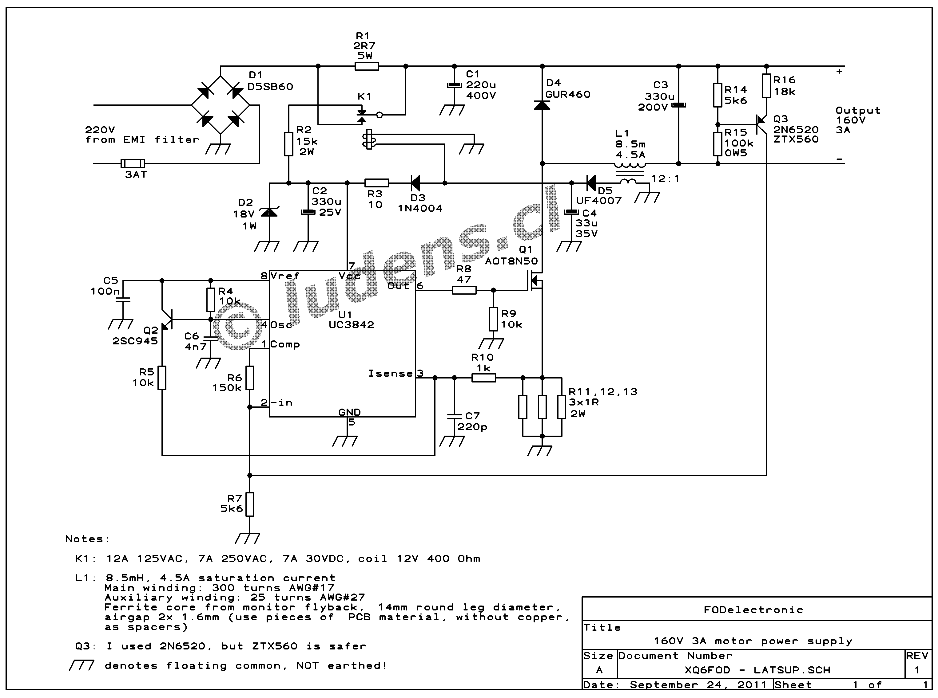
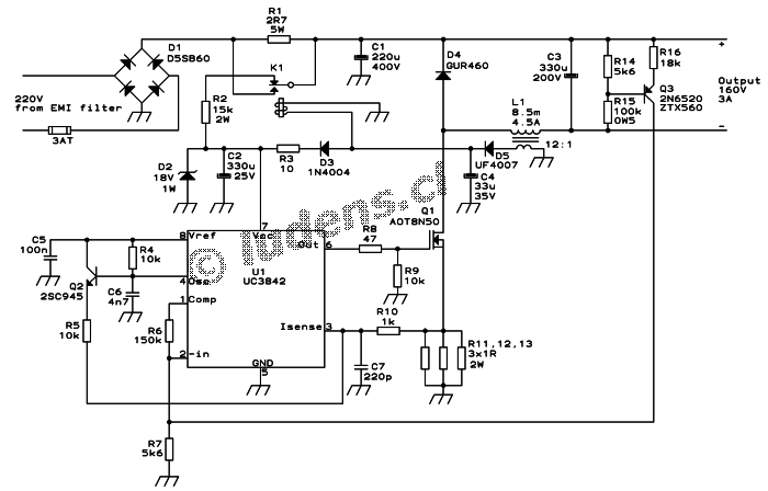 The
circuit of this power supply is rather unorthodox. As this power supply
is for a 500 watt level, most designers would make a
fully fledged half bridge or even full bridge circuit. But my lathe
motor doesn't need its DC to be insulated from the grid! So I made
a simple buck converter circuit, utilizing just one MOSFET,
controlled by the ubiquitous UC3842. To make matters more fun, I placed
the MOSFET on the negative side of the circuit, allowing me to use a
cheap N-channel MOSFET, directly driven by the IC. Some people would
have trouble visualizing this as a simple buck regulator, without first
reading this explanation! But it is.
The
circuit of this power supply is rather unorthodox. As this power supply
is for a 500 watt level, most designers would make a
fully fledged half bridge or even full bridge circuit. But my lathe
motor doesn't need its DC to be insulated from the grid! So I made
a simple buck converter circuit, utilizing just one MOSFET,
controlled by the ubiquitous UC3842. To make matters more fun, I placed
the MOSFET on the negative side of the circuit, allowing me to use a
cheap N-channel MOSFET, directly driven by the IC. Some people would
have trouble visualizing this as a simple buck regulator, without first
reading this explanation! But it is.
One matter that requires attention with such a circuit is that the
output is referenced to the positive rail, so it's galvanically far
away from the control IC, making voltage feedback harder to implement.
I have seen people who solve this problem by using
optocouplers, and so
these poor guys have to deal with all the instabilities of those
devices! Instead I used a simple current transmitter employing a small,
inexpensive high voltage PNP transistor and making use of its very high output resistance. It will inject a current into
the UC3842's feedback circuit, that is cleanly proportional to the
output voltage. This has proven a very effective solution, despite its
extreme simplicity.
This buck converter needs to operate at duty cycles that can far exceed
50%. For that reason I used slope compensation, implemented around Q2.
Without this, the loop would not be stable.
An important difference between this power supply and most others, is
that this one needs to start quickly, under full load, and needs to be
able to be restarted very soon after being shut down. This capability
was highly desirable in order to seemlessly incorporate this power
supply into my lathe, which has an AC-solenoid-latched run switch.
After the rectifier I used a relatively small input filter capacitor,
since a high ripple on it won't cause any trouble in this circuit, and
the small capacitor improves the input power factor. Also the small
filter capacitor helps to make the power supply run out of charge
quickly enough after being shut off, to keep it from driving the motor
for a noticeable time after being switched off. To limit the inrush
current, there is a 2.7 ohm resistor, which gets shorted out as soon as
the power supply has come up to normal operating voltage.
The supply for the UC3842 needs to rise quite fast, but also
needs to have a large reserve capacitance, to be able to power the IC
from the moment its undervoltage lockout releases, to the time it has
come up to normal voltage, spinning up the motor during this process.
So C2 is 330uF, a much larger value than what's usually
required, and it is charged through a 15k resistor from the rectified
mains to bring it up quickly, but to avoid excessive heating this resistor also gets de-activated
by the same relay that shorts out R1, as soon as the power supply
runs. As is usual with the UC3842, during normal operation the IC is
powered from an auxiliary winding on the output inductor (or
transformer, if there was one).
The output inductor has a value of 8.5 millihenries, and must not
saturate at currents up to at least 4.5A. I wound this inductor on a
plastic bobbin made on my lathe, using the ferrite core of an old CRT
monitor's flyback transformer. The core needs to be airgapped. The wire needs to have an
adequate size for 3A continuous duty, and the auxiliary winding that
powers the control IC has one twelfth the number of turns of the main
winding, and can be made from rather small wire.
If you click the schematic, you will get a large version of it, which
also includes the details of this inductor. If you don't find a core
exactly like mine, you can of course use find a ready made inductor, or
custom wind your own, using the info above, and the basic calculations
on my Transformers and Coilspage.
The full size circuit also gives basic data on the relay, and a
warning note that I will repeat here: The ground symbols on this
schematic refer to a floating common, and they must not be connected to
physical earth ground!
Note that in the schematic I mention an EMI filter. My lathe already
has one built in, intended to absorb the spark interference of the
original induction motor's starting circuit, so I didn't include any
additional filter in my power supply. But if you intend to use a supply
like this in some other application, you must include an EMI filter at
the input, or there will be serious interference emitted!
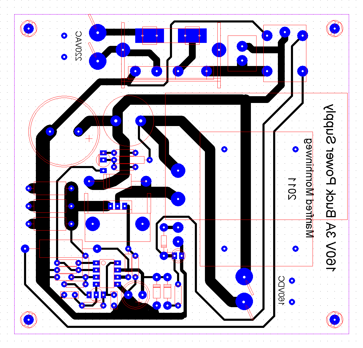
 To make a compact and robust power
supply, I indulged in the luxury of building it on a printed circuit
board. All of the parts are on the board, which is single-sided and has
all of the connections on them. It is doubtful to what extent other
builders will be able to use this board layout, because it is heavily
dependent on the sizes and shapes of the exact components I used.
Anyway I'm providing the design here, seen from the component side. If
you click on it, you will get a larger version. You can see roughly
what part goes where, although the parts are not identified, only
outlined. It should be easy enough to populate the board following the
schematic.
To make a compact and robust power
supply, I indulged in the luxury of building it on a printed circuit
board. All of the parts are on the board, which is single-sided and has
all of the connections on them. It is doubtful to what extent other
builders will be able to use this board layout, because it is heavily
dependent on the sizes and shapes of the exact components I used.
Anyway I'm providing the design here, seen from the component side. If
you click on it, you will get a larger version. You can see roughly
what part goes where, although the parts are not identified, only
outlined. It should be easy enough to populate the board following the
schematic.
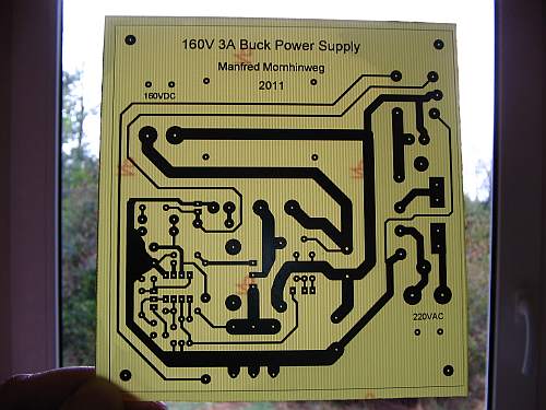
Here is the copper pattern for
this board. I saved it in x5 size, so if you downsize it by a
scale of 5, your printer should put it out at the precise scale, as
long as all programs work as they should, and no program does stupid
things on its own... But if they do, you will have to scale it
manually. It helps to know that the board size is 119.4 x 114.3mm.
Note that the board has several unconnected pads. These are intended
just as drill guides, to make holes through which to anchor the
inductor, and tie down the input and output wires.
 Here
is the board, just out of the ferric chloride bath. It has to be cut
down to its final size, drilled, the photoresist stripped off, and
protected by some solderable varnish.
Here
is the board, just out of the ferric chloride bath. It has to be cut
down to its final size, drilled, the photoresist stripped off, and
protected by some solderable varnish.
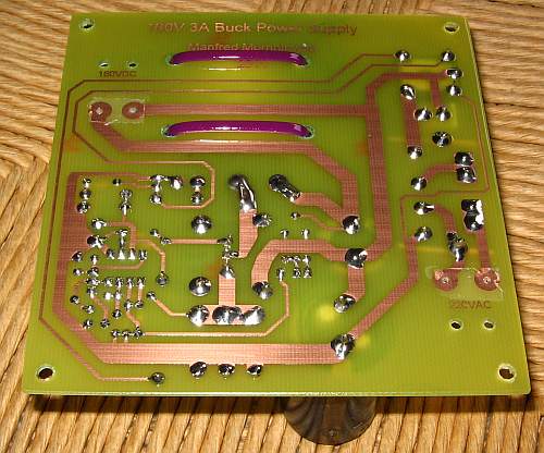 And
here the board has been assembled. After assembly I applied a thick
coat of acrylic varnish, to prevent creepage between nearby traces and
pads. Only the input and ouput pads, which had not yet been
soldered, were protected with little pieces of masking tape before
spraying on the varnish.
And
here the board has been assembled. After assembly I applied a thick
coat of acrylic varnish, to prevent creepage between nearby traces and
pads. Only the input and ouput pads, which had not yet been
soldered, were protected with little pieces of masking tape before
spraying on the varnish.
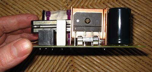 Seen
from the side, the compact built height of this power supply is
apparent. The room inside the base of my lathe is precisely 50mm high,
and the largest free space is 120x115mm. This dictated both the size of
the board, and the height of the tallest components. The full height of
the power supply, from the soldered pins to the tops of the tallest
parts, is 46mm.
Seen
from the side, the compact built height of this power supply is
apparent. The room inside the base of my lathe is precisely 50mm high,
and the largest free space is 120x115mm. This dictated both the size of
the board, and the height of the tallest components. The full height of
the power supply, from the soldered pins to the tops of the tallest
parts, is 46mm.
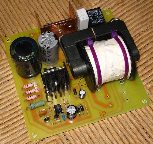
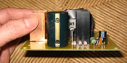 And
here is another view. You can see how some power components are
installed with long legs, to raise them above the board and allow them
to get good air flow.
And
here is another view. You can see how some power components are
installed with long legs, to raise them above the board and allow them
to get good air flow.
This little power supply packs a lot of power into a small size. After
all, it works at the 500 watt level! When machining larger parts, I
often work hard at the limit of the lathe, because that's fastest. The
heatsink cooling the MOSFET gets pretty hot under such conditions, but
since the MOSFET is used well below its limits, the operating
temperature is still completely safe. The other parts heat up much
less. The inductor stays cool, because it's significantly oversized. I
didn't have a suitable smaller ferrite core on hand...
With the DC motor and this power supply, my lathe
now works far better than when new. This motor has better
torque than the original one, and doesn't vibrate. There isn't such
a huge inrush current when starting, as there was with the
induction motor and its capacitor starting system. And in the
two years since I built this power supply, it has worked perfectly.
Back to homo ludens electronicus.
 To make a compact and robust power
supply, I indulged in the luxury of building it on a printed circuit
board. All of the parts are on the board, which is single-sided and has
all of the connections on them. It is doubtful to what extent other
builders will be able to use this board layout, because it is heavily
dependent on the sizes and shapes of the exact components I used.
Anyway I'm providing the design here, seen from the component side. If
you click on it, you will get a larger version. You can see roughly
what part goes where, although the parts are not identified, only
outlined. It should be easy enough to populate the board following the
schematic.
To make a compact and robust power
supply, I indulged in the luxury of building it on a printed circuit
board. All of the parts are on the board, which is single-sided and has
all of the connections on them. It is doubtful to what extent other
builders will be able to use this board layout, because it is heavily
dependent on the sizes and shapes of the exact components I used.
Anyway I'm providing the design here, seen from the component side. If
you click on it, you will get a larger version. You can see roughly
what part goes where, although the parts are not identified, only
outlined. It should be easy enough to populate the board following the
schematic.