Quick and dirty Geiger counter
Many years ago, when I was a young guy, and the Chernobyl
nuclear power plant blew up, I wanted to have a means to detect any
significant radioactive fallout. I live in the southern hemisphere, so
I could count on at least a few days before the dirty cloud might reach
me. I knew a military surplus store, and I had seen some small old
Geiger tubes there. So I went and bought a JAN5890, the cheapest they
had. After all I was a poor student in those years!
I cobbled
together a very quick and dirty high voltage supply, using a voltage
doubler off the 220V grid, added a small audio amplifier, and that
enabled me to hear the ticks and pops and crashes. I counted them with
the help of a stopwatch. For the next days and weeks, I
regularly
measured the background radiation that way - and indeed, roughly one
month after the Chernobyl disaster, I was able to detect
a slight
rise in the background level, which then slowly tapered off over
several months.
After that I put my little Geiger tube in storage. A long storage it
would be.
Many
years later, prompted by certain ugly events that unfortunately are
happening in this world, and in the same area of it, although for
different reasons, I again saw reason to dig my Geiger tube out of
storage, and again cobble together a very basic Geiger counter. Only
that this time it was just one step more refined: A regulated
DC-DC converter, instead of a plain old voltage doubler!
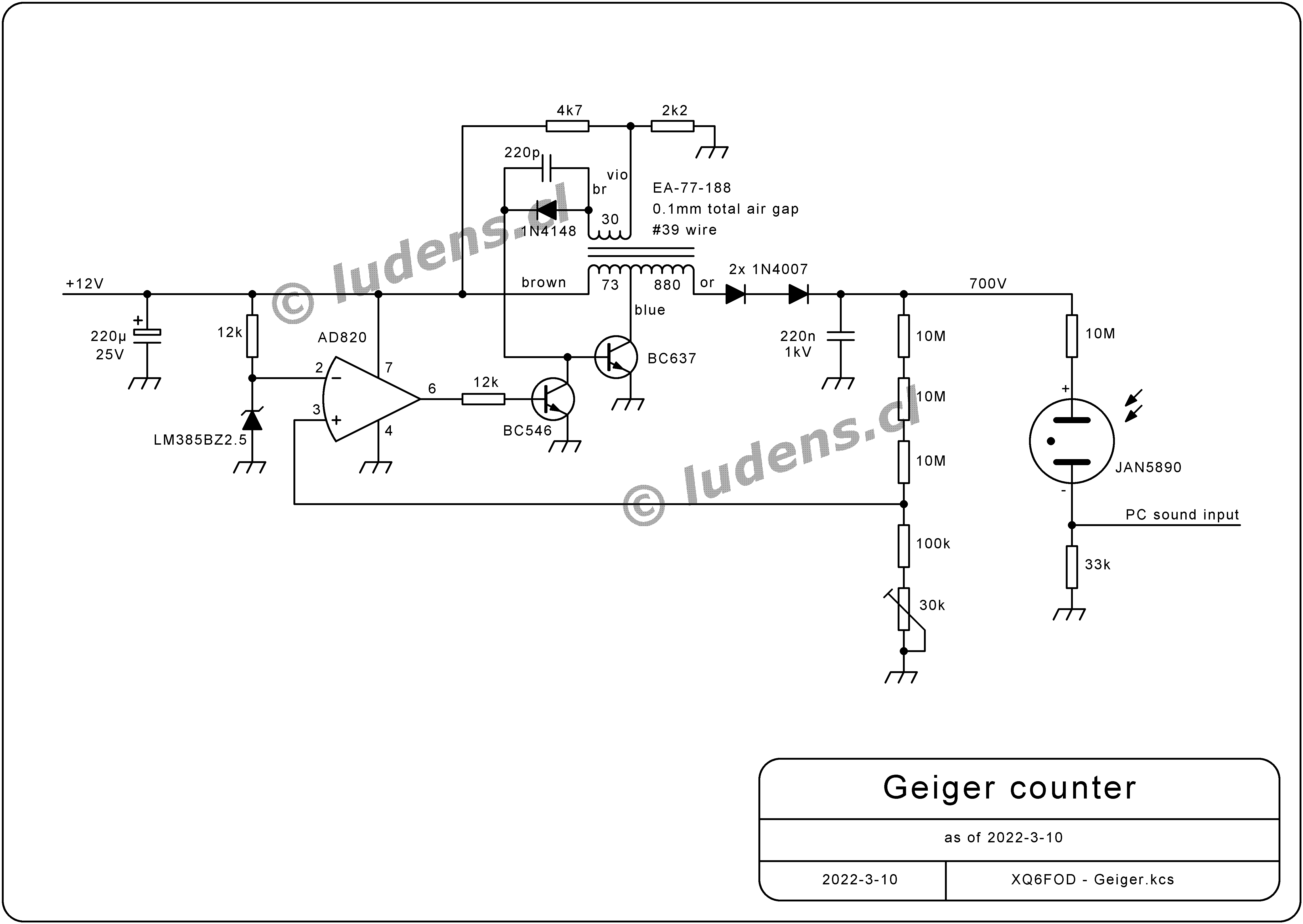
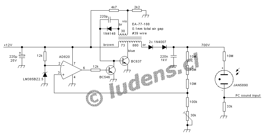 The
circuit is a little self-oscillating flyback converter, using
an
airgapped ferrite core and a small transistor, with a voltage
regulating circuit wrapped around. It runs off a nominally 12V supply,
but it accepts a wide range of input voltages, and it consumes just a
few mA. The lack of any loop compensation results in the converter
operating with pulse trains separated by pauses, which helps conserve
power.
The
circuit is a little self-oscillating flyback converter, using
an
airgapped ferrite core and a small transistor, with a voltage
regulating circuit wrapped around. It runs off a nominally 12V supply,
but it accepts a wide range of input voltages, and it consumes just a
few mA. The lack of any loop compensation results in the converter
operating with pulse trains separated by pauses, which helps conserve
power.
Plain common 1N4007 diodes are used as fast rectifiers.
They aren't fast, of course, but flyback converters have the advantage
that diode recovery speed is quite uncritical, so these slow diodes
work just fine. Two are used in series, because a single one would be
running pretty close to its breakdown voltage.
The transformer
was entirely wound with #39 wire. Of course it's inefficient to use the
same wire size for the low voltage, high voltage and feedback windings,
but the output power required is so tiny that this doesn't matter.
Note
that the phasing of the windings must be as shown, or the oscillator
won't oscillate. Left is left, right is right, no phasing dots are
needed... If you want phasing dots, draw them yourself, all
on
the same side!
Instead of building a little audio amplifier, a
pulse counter, etc, I simply connected the output of the Geiger tube to
one channel of the line level input of my PC's sound system. That
allows me to listen to the pops in the PC speakers, and record the
pulses over any time desired, using any sound recording software. Later
the recording can be watched with your favorite sound editing software.
With the old but good software I use, it looks like this:
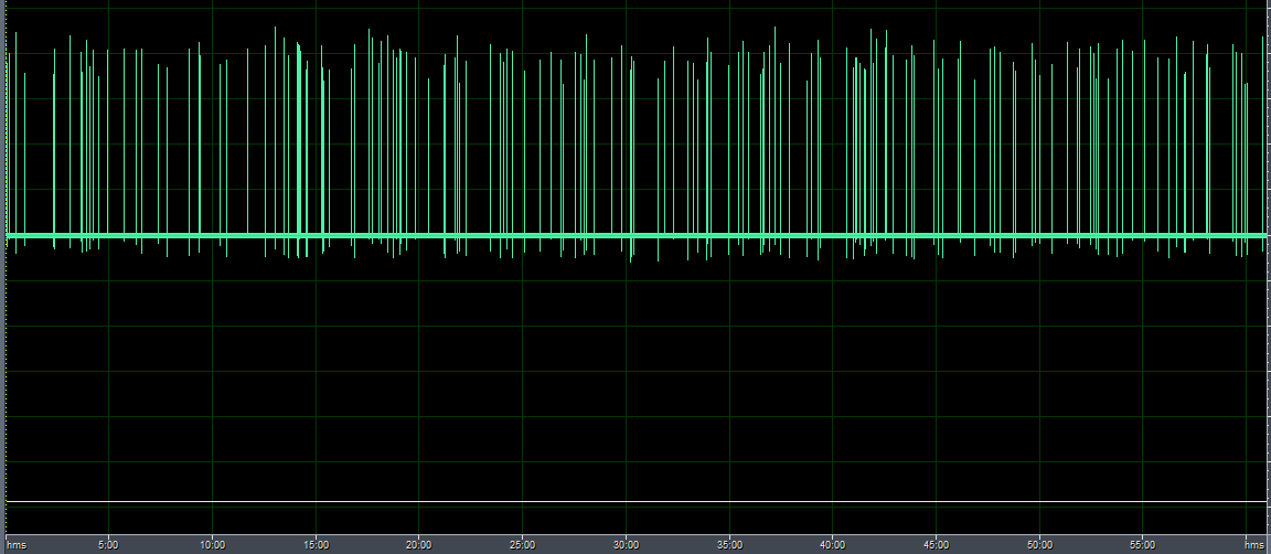
The
audio software allows zooming in, to the point of watching the waveform
of each pulse, telling double and triple pulses from simple ones, and
of course it's easy to manually count the pulses per unit of time. One
can also nicely see how the background radiation sometimes seems to
come in waves.
The JAN5890 is a very small Geiger tube, so its
sensitivity is very low. With the background radiation at my place, it
gives only a few counts per minute. Still, by integrating long enough,
one can easily detect the radiation of a moderate amount of any
potassium salt, including potassium nitrate fertilizer, and sodium-free
salt substitute from the supermarket! And a tiny sample of
uranium nitrate, out of an old black-and-white photography
lab, drives the tube crazy.
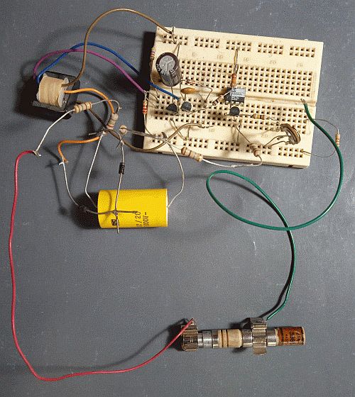 Maybe
someday I will build this Geiger counter in a nice way, portable,
battery-operated, with a PIC added to count the pulses and present them
on a display as total dose, pulses per minute, per second, etc. But
being old, tired and lazy, so far I only assembled the circuit
on
a small protoboard. The high voltage circuitry is insulated by fresh
air, still the best and cheapest insulation material we have!
Maybe
someday I will build this Geiger counter in a nice way, portable,
battery-operated, with a PIC added to count the pulses and present them
on a display as total dose, pulses per minute, per second, etc. But
being old, tired and lazy, so far I only assembled the circuit
on
a small protoboard. The high voltage circuitry is insulated by fresh
air, still the best and cheapest insulation material we have!
Note
that the big yellow high quality polypropylene capacitor is total
overkill! A plain cheap ceramic capacitor would suffice, even one of a
much smaller value than the 220nF this one has, and that's
what I
would use in a definitive built of my Geiger counter. But for the test
I used what I had lying around on the desk.
If you need to
buy a Geiger tube, I suggest that you get a bigger one than mine, to
get higher sensitivity. Usually we want them for measuring
background radiation, and perhaps to go treasure seeking for
any
radioactive minerals, or to detect radon in our basements. All these
are pretty weak radiation levels, making a large size tube most
appropriate. Also you need to determine whether you are happy with just
detecting gamma radiation, which is typical of glass Geiger tubes, or
if you want beta and perhaps even alpha too. My ceramic 5890 tube
detects mostly gamma, but also beta when it's strong enough.
Definitely no alpha, which needs a tube with a very thin window. Such
tubes are fragile. In most cases just detecting gamma is good enough.
My
little high voltage supply can easily be reconfigured for higher or
lower voltages, as needed by the tube you get. It's just a simple
matter of recalculating the voltage divider of the regulating circuit.
The
core type number given in the schematic is an Amidon part number. You
can as well use any other double-E ferrite core of comparable
dimensions. The exact ferrite type is uncritical, given the use of an
air gap. Surplus electronic equipment these days is full of
such
small ferrite transformers. Slowly heating them up in an oven, to maybe
120°C or so, will soften the glue holding them together, allowing easy
disassembly (with thermally insulating gloves!), after which you can
unwind the original windings, and make the custom winding required for
this circuit. And then re-assemble the core with adhesive tape of
suitable thickness between the halves, to create the air gap. To create
the 0.1mm total air gap I used, you need to separate the core halves by
0.05mm, of course. Scotch "Magic" tape is what I used. It has that
thickness.
Back to homo ludens
electronicus.