12V powered, 4x15 Watt quad amplifier
 In the "good old
days", computer sound cards came with their own built-in power amplifiers.
But these good days have long gone, and my newfangled Soundblaster Audigy
has just line/headphone level outputs! The four channel amplifier shown
here was build to fill this gap. I installed it inside the computer, so
that I could continue using my four high quality, but passive speakers,
without the hassle of an external amplifier.
In the "good old
days", computer sound cards came with their own built-in power amplifiers.
But these good days have long gone, and my newfangled Soundblaster Audigy
has just line/headphone level outputs! The four channel amplifier shown
here was build to fill this gap. I installed it inside the computer, so
that I could continue using my four high quality, but passive speakers,
without the hassle of an external amplifier.
A PC power supply delivers 3.3, 5 and 12 Volt at a current high enough
to snatch some off for audio. Of these, of course the 12V output is most
convenient. These power supplies also have a -12V output, but with a very
tiny current capability - definitely not enough for an amplifier! So, the
design requirement was a simple, inexpensive amplifier, that would deliver
decent power and good sound quality while working from a single 12V supply.
For this purpose, of course the amplifier chips made for car radios have
a lot of appeal! The only problem with them is that there are so many different
ones, that it's almost impossible for the casual builder to select just
the optimal device! I solved this problem in a very practical way: I went
to the nearest electronic parts shop, looked through their price list,
and bought the least expensive chips they had in their stereo BTL car power
amplifier section! I went home with them, downloaded the data sheet, and
built my amplifier.
Modern 4 channel car radios have amplifier chips that implement all
four channels on a single chip. And then, some of these chips provide a
whopping 50 Watt and higher output power, per channel! They use integrated
voltage converters for this. But such high power would have been pure overkill
for me. Also, the PC power supply can usually spare only a few Ampere,
not the 20 or more Ampere the high power chips can demand! While I would
have liked a 4 channel chip with about 20 Watt per channel, the local parts
store didn't have any yet, so I opted for two TA8215AH stereo chips, selected
by their low price in this particular store.
The design? Oh well, there isn't much to it. The circuit I used is almost
an exact copy of the circuit suggested in the Toshiba data sheet. I only
made a very few changes, but including an important one - the one that
makes it possible to use this circuit in a computer, without getting power
supply and hard disk noise!
These chips can deliver 15 Watt RMS per channel, into 4 Ohm loudspeakers.
That's more than enough even for loud home use. The peak power current
consumption, when saturating all four channels at the same time, would
be 12A, which gives good chances that the computer won't reset from power
supply shutdown in such a situation! When using 8 Ohm speakers, the output
power and the current consumption are cut down to one half. In fact, that's
my situation, because my present speakers are 8 Ohm.
The amplifier has a typical distortion in the neighborhood of 0.04%.
That's good enough, in my opinion, for a computer sound system, while surely
with discrete parts I could have obtained even lower distortion. The gain
delivered by the TA8215 is a whopping 50dB, which is MUCH more than needed.
So I had to include an attenuator at the input, in order to be able to
use the full dynamic range of the sound card.
 Here
is the complete schematic diagram of one stereo amplifier. Of course, I
used two of these for my quad amplifier - and if you want, you can use
three to make a 5.1 amplifier! You can click the schematic to get a higher
resolution version for printing.
Here
is the complete schematic diagram of one stereo amplifier. Of course, I
used two of these for my quad amplifier - and if you want, you can use
three to make a 5.1 amplifier! You can click the schematic to get a higher
resolution version for printing.
R1 with R2 forms a voltage divider that attenuates the input signal
by 24dB. Considering the chip's 50dB gain, that still leaves 26dB overall
gain, slightly more than enough to fully saturate the amplifier when the
sound card works at maximal output. C1 blocks DC at the preamplifier input.
C2 is the ground return of the feedback circuit. These two capacitors need
to be in the ratio shown, in order to suppress switching clicks when powering
the circuit on and off. The output pins 15 and 16 are connected directly
to the speaker, while C7, R6, C8 and R7 provide the proper load phase shifting
to avoid high frequency instability.
The lower side of the schematic shows the same circuit repeated, for
the other channel inside the chip.
The power supply is decoupled with a rather small 100uF capacitor. That's
enough for higher frequency decoupling, and at lower frequencies anyway
the large capacitors in the PC power supply are fine. Pins 10 and 17 supply
the power amplifiers, while pin 9 provides power to the pre stages. This
power is filtered by C3. The power control pin 4 allows to shut down the
amplifier, an option not used here, so it's tied to 12V. Pin 1 is a muting
input, also not used, and left open.
If you compare this schematic to the one in Toshiba's data sheet, you
will notice that it's almost an exact copy, except for R3! Toshiba ties
the input ground directly to the output ground. In a PC, this leads to
trouble! A computer is a noisy machine. There are quite strong noise currents
circulating through ground, for example. If you tie all grounds together,
it could well happen that a noisy power ground return from the hard disk
takes a route through this power amplifier and the sound card! This makes
some nasty noise show up in the speakers.
It's important to understand that the TA8215, like many such chips,
has the preamplifier internally separated from the power amplifier. This
is very useful to get rid of the described ground loop problems! I left
the input ground separated from the output ground, except for the 10 Ohm
resistor. If you happen to use this amplifier with a signal source that
has a floating ground, the resistor is low enough to apply proper power
ground to the preamplifier stages, and it works well. But if you install
the amplifier in a PC, the 10 Ohm resistor is high enough to break
up the ground loop that would otherwise form! All sensitive input points,
such as voltage divider grounds, feedback returns, and ripple filter capacitor
ground, are directly connected to the soundcard ground, and separated by
the resistor from the power ground. The result is a very good rejection
of noise. In my system, I can't hear power supply noise at all, but if
I short out the resistor, the noise is all over the place!
The heatsink contact surface of the TA8215 is internally connected to
the input section ground too. So, you must connect the heatsink to
the input ground, not the power ground.
Construction
For this project, I actually overcame my natural laziness and designed
a printed circuit board! The reason is simply
that, to my surprise, this IC does not have the long standing standard
pin separation of 2.54mm, which would be one tenth of an inch to US citizens,
but instead it uses a pin spacing of exactly 2mm! I had no project board
with that hole spacing, and I doubt that any exists. So it was either connecting
little wires directly to little pins, or make a PCB. You are welcome to
use my PCB layout, as well as the component placement
guide. Both are for the complete 4-channel board, and seen from the
components side. If you just want to build a stereo amplifier, you use
one half of the layout, and if you want to make a 5.1 amplifier, cut and
paste one of the halves to get three sections!
Populating the board is straightforward, and the circuit should work
on the first try. Use a solder lug under one of the IC mounting bolts,
to connect the heat sink to the pad provided for that purpose on the PCB.
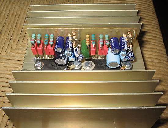
If you use the photo at the top of this page as a component placement
guide, don't be surprised to find that seven of the resistor/capacitor
snubbers at the outputs are of one kind, while the eight is different.
The culprit of this is a stupid sales clerk in an electronic parts store,
who apparently was unable to count to eight! I ordered 8 of each part,
and got just seven, so I had to make up for the difference with parts salvaged
from old equipment. The electrolytic capacitors also were all recycled
from junked equipment, so don't be surprised if you notice that the two
220µF capacitors have different colors and sizes...
Speaking of capacitors, a 16 Volt rating is good enough, and anything
higher is OK too. Resistors are all 1/4 Watt carbon film, like in all my
projects when nothing different is noted. When buying the 150nF plastic
capacitors, watch for their size. The correct ones have 5mm pin spacing,
and measure about 7x3mm (the height is irrelevant). Many capacitors of
this value are larger, and won't fit the board.
The heat sink shown in the photos was used because I had it. For normal
use, it's vastly oversized. It would be about right if you like to listen
to very loud music for long times. Anyway, use heatsink compound between
the chips and the sink.
Be careful with the 12V line that runs behind the chip's pins. It's
very close to the heatsink. When cutting the PCB down to size, you want
to have about half a millimeter of board left after that trace and the
edge. More, and it won't fit; less, and you will have to use a layer of
insulating tape between the heat sink and the board!
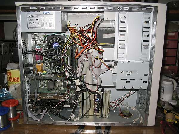 Here you can see
the inside of my PC, with the quad amplifier installed at the bottom. The
heatsink must be insulated from the ground, to maintain the full effect
of the ground loop breaking resistor R3. I installed it on little scraps
of self-adhesive rubber, and tied it down with two cable ties - quick and
dirty, but works well.
Here you can see
the inside of my PC, with the quad amplifier installed at the bottom. The
heatsink must be insulated from the ground, to maintain the full effect
of the ground loop breaking resistor R3. I installed it on little scraps
of self-adhesive rubber, and tied it down with two cable ties - quick and
dirty, but works well.
The inputs were directly soldered to the sound card, right behind its
connectors. So the connectors remain available for external devices. The
outputs go to four RCA jacks mounted on a small black plastic project box,
installed on the rear of the cabinet (barely visible above the Sahne-Nuss
chocolate container). The 12V power and ground were taken from an unused
output of the power supply, with the 12V routed a front panel switch that
allows to power the entire amplifier off and on. This is a good feature,
for the times when I want to use the computer as a signal generator, and
don't want the noises to blare out of the speakers! It's also great for
web surfing, to quickly shut down the audio from those web sites that keep
forcing undesired background music on you!
By the way, mine is a very silent PC! The fans in the power supply and
on the CPU run very slowly, in almost complete silence, because I connected
them to 5V instead of the normal 12V. The cabinet fan was eliminated, and
the tiny fan on the nVidia video card, which was absurdly noisy, was also
eliminated and replaced by a large finned fanless heat sink. The hard disk
was foam-mounted inside a sealed black metal box, and this box was in turn
foam-mounted in the cabinet! To ensure adequate cooling of the hard disk,
I sprayed the disk and the box (inside and out) flat black, so it can cool
by radiation alone! It has worked fine for several years now, so don't
tell me that I'm cooking my poor PC!
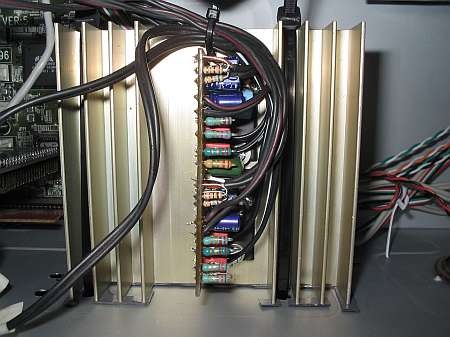 Finally, here's
a closeup view of the quad amplifier installed in the PC. You can see that
despite everything ugly said before, it looks rather decent. And it works
very well, which is the important point!
Finally, here's
a closeup view of the quad amplifier installed in the PC. You can see that
despite everything ugly said before, it looks rather decent. And it works
very well, which is the important point!
Back to homo ludens electronicus.
 Here
is the complete schematic diagram of one stereo amplifier. Of course, I
used two of these for my quad amplifier - and if you want, you can use
three to make a 5.1 amplifier! You can click the schematic to get a higher
resolution version for printing.
Here
is the complete schematic diagram of one stereo amplifier. Of course, I
used two of these for my quad amplifier - and if you want, you can use
three to make a 5.1 amplifier! You can click the schematic to get a higher
resolution version for printing.