The Awfully Antique Audio Amplifier
This project was born out of schematic
diagram drafting woes, so you will have to read a lot of related trivia, before
we come to the project proper!
While drawing a schematic diagram the other
day, using my more-than-20-year-old CAD software, I started thinking. A rare
occurrence, yes. This software is still DOS-based, and attempts to directly
write to the graphic card, printer, plotter, directly read the mouse, and so on.
It's becoming an ever larger problem to keep it running under Windows XP, Linux
or whatever. So, once again, I started thinking about upgrading. But the
present-day version of this software is so unspeakably expensive, that
the company selling it doesn't even dare to mention the price on their website,
and instead asks potential would-be customers to contact their sales personnel!
These probably have been trained to make an enormous number sound smaller.
And then, this new version requires a super
PC, with the latest, fastest Pentium 4, at least a gigabyte of RAM, and so on.
The basic demo version of the program comes on a DVD, because it wouldn't
even fit on a CD. Instead, the 20 year old version I have came on two
floppies, runs perfectly well on an 8088 CPU with 640kB RAM, and does absolutely
everything I need. So, why upgrade? Only to follow fashion? Come on! Case
closed.
And then, I kept thinking. An even rarer occurrence, certainly. This
time my thoughts roamed into the reigns of schematic diagram symbols. As
you might have heard before, the best things about standards is that there
are so many to choose from. Europeans use one style, Americans use a different one, others use combinations
of them, the IEEE tries to impose their standard on the world,
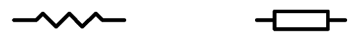
national standard institutes in many countries run against that, and so on. For
example, resistors are drawn in two totally different styles:
I was raised on American ham radio
literature, such as the ARRL's Radio Amateur's Handbook, so I learned
that the zigzag line was a resistor. It makes some sense! One
can imagine the poor electrons having trouble going that route without loosing control
in those sharp corners, and having horible traffic accidents.
But later, at university, my professors
didn't want any zigzag lines! The university was better connected to Europe than to
the USA, so I had to change style, and use the rectangular box. After all, that
makes sense too! One can imagine it as a block of some
resistive material. Think about a rod of charcoal, or graphite. And from there
to the carbon composition resistor, it's a small step.
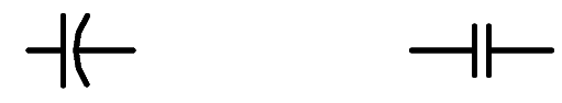
With capacitors, the difference between standards is
smaller:
Americans for some reason like to make caps with one warped plate, resulting in
uneven spacing between the plates, I suppose. Europeans instead use nice straight
plates and uniform spacing. The European style is a lot more logical, but Americans
say that their style allows to identify the side of the capacitor that is
connected to the external foil, which is important in some circuits. A good
point. Anyway, sometime in the 1990's I switched from the roundish to the
straight style.
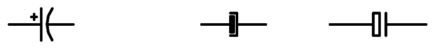
But with electrolytic capacitors, the
styles differ a lot more:
The first two styles are used both in the
US and in Europe, the third only in Europe,
to my knowledge (which isn't much). Which is more logical? Certainly not the last one,
which is too cryptic. A hollow anode? I preferred the second one. Most of my
drawings use it. But it's not optimal.
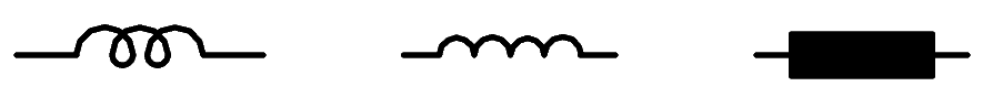
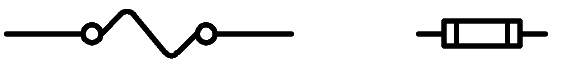
A totally stupid situation happens with
coils. Just look!
A coil is a spiral of wire, nothing else. So the first
picture makes some sense, but it looks more like a knot than a coil to me. In
the second picture the poor coil was stretched out too much, and looks dangerously
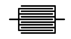
similar to a resistor. The first style is rather antique, the second is
what Americans use nowadays. Europeans instead want everybody to use the third
symbol: A rectangular black box! Go figure. How can a homo sapiens electronicus
infer that a black rectangular box is supposed to mean a coil of wire? It's
beyond me. I have always strictly refused to use that symbol, to the chagrin of
my European-educated professors, and some European engineers I met at my job.
Instead, I have sometimes used this symbol for striplines. It does actually resemble
them!
Another such case is the humble fuse.
It seems that everybody draws fuses as best he likes. Americans seem to prefer
either of these symbols:
The first might be confused with a resistor
by some. In any case, it doesn't give the idea of a fuse. The second at least
looks like a typical little glass fuse.
Europeans instead tend to be more
abstract. They like to draw fuses like this:
The version on the right might be
considered to look like some fuses, but it can be easily confused with the
symbol often used to indicate ferrite beads on a wire! And the symbol on the left is
another one that I would like to have explained by its inventor!
At this point, I had made up my mind: New
symbols are needed! If anyway people can't agree about which to use, then why
shouldn't I define my own ones? And change them as needed? OK, here I go!
Let's start with the capacitor. Most
capacitors we use are of some sort of multilayered construction, with all of the
layers of each pole connected at their end. This leads to an obvious and
entirely logical symbol for such capacitors:
I hope you like it! I do.
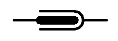
Electrolytic capacitors are normally elongated, and
use a roughened, thick anode, in some sort of container. That must be
the basis for a symbol representing electrolytic caps. And since so many things in a
schematic are too squarish, I rounded off the corners of my symbol:
Nice, huh?
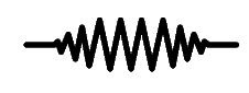
I don't want to make things too complicate. Symbols should be recognizable. So I
decided to keep the zigzag line for resistors, but give it a distinctive,
beautifully curved look, to take the rough edge off all those corners. Resistors
are soft things, after all, damping circuits, soaking up energy, getting cozy
warm...
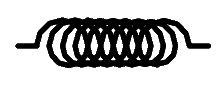
Likewise, I decided to keep the basic,
antique, original and best symbol for a coil, but make it look better
shaped:
This should be obvious enough to anyone,
and also will place emphasis on the need to carefully wind such coils into a
beautiful, even, round shape! It's just a pity that my ages-old schematic
drafting software is a little bit limited in resolution, so that I cannot make
the round shapes look perfect. At least my good intentions are clear,
right?
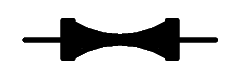
Since there is no reasonable symbol for fuses
in existence, I though long and hard about how to draw fuses. My head hurt from
it. It was a severe existential problem, for about five minutes. The best way
to draw a fuse would be, obviously, to make a bottleneck in the line representing
a conductor. The problem is that my stupid drafting software cannot draw a
line thinner than one pixel! So, I decided to blow up the whole thing. Here we
have the new fuse symbol, a blown-up bottlenecked conductor:
This symbol indeed looks a bit like the element in
a high current fuse!
Now I became bold! The next symbol to
attack was the ground. As you might know, engineers differentiate between earth
ground, chassis ground, signal ground, protection ground, power ground, European
ground, American ground, my ground, your ground... Whenever you fnd any symbol
with just one connection, that you cannot recognize, chances are it is a
ground! Here are a few samples:
At first, I thought about simply rounding
off one of these symbols, to make it look nicer, and more vertically developed,
to imply that it digs down into the ground:
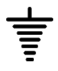
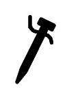
But then I thought that something radically
new was needed, and invented a new ground symbol: A real, true grounding stake,
complete with a wire tied to it!
It's lovely, right?
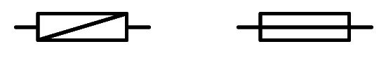
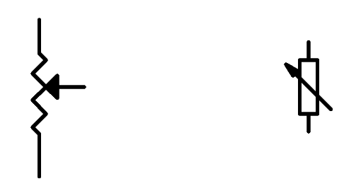
Potentiometers, like
those used for volume control, are also a bit problematic. Americans like their
cursors to jump from zig to zag on their resistive elements, while Europeans often
prefer shooting an arrow through theirs, just like Cupid would do with some loving heart out
there:
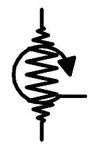
But the fact is that most potentiometers
are rotary! So I decided to invent a symbol for potentiometers that is of course
based on my resistor, but also contains the concept of the rotating cursor. Here
it is:
It looks a bit antique, but beautifully so,
don't you find?
At this point I got tired of thinking. Come
on, I don't have to think all day long, do I? It's tiring, really! So, for the
rest of the symbols, I decided to keep the basic existing designs, but just draw
them a little better: A curve here and there, nicer angles, and so on.
The biggest controversy regarding transistors is whether or not to draw a circle around them. I
usually don't do so. But there has been an instance when one of my schematics
was rejected by a magazine, for not having those donuts around the transistors!
The pro-donut gang says that these circles represent the encapsulation of a
transistor. Without a donut, it would be naked. The anti-donut activists instead
counter that if that were true, we would also have to draw a circle around every
diode, resistor, capacitor, and so on! After all, they are all encapsulated
too!
I finally opted for adding those donuts, even
if only for the aesthetic purpose of having a few more
round shapes in those overly squarish schematics.
These are the original symbols for transistors that came with my
schematic software:
And here are my redrawn, embellished ones.
They have nothing out of the ordinary, just are better made!
Like this, I redefined (and refined!) a lot of
symbols.
At last: The AAAA!
With all the new improved symbols installed in my
20 year old CAD software, I had to come up with some deserving project! Looking
around my workshop to see what I could draw, I came onto a box full of old
Germanium transistors. Oh, old memories came up!
Very old memories,
actually, this being me! Memories of building my first radios, as an 11 year old
kid, in 1977, but using schematics published in magazines dating to 1962, not
realizing that the electronics world had changed a little bit since then! The
European magazines often requested OC72 transistors, while American ones
typically used the CK722. If you remember them, you are old, don't deny it! The
radio spare part stores didn't have them anymore in 1977. At least there was one
guy in one of those stores, who knew what they were, and sold me some AC125
transistors, which he swore were exact replacements. My circuits often didn't
work, so I blamed him, until finally I did get a few real and true OC72's,
from a lab that had no use for those oldies anymore. When my projects still
didn't work, it dawned to me that maybe something else was wrong, such as the
schematics in those magazines having printing errors... Of course, it couldn't
be
me
who was wrong!
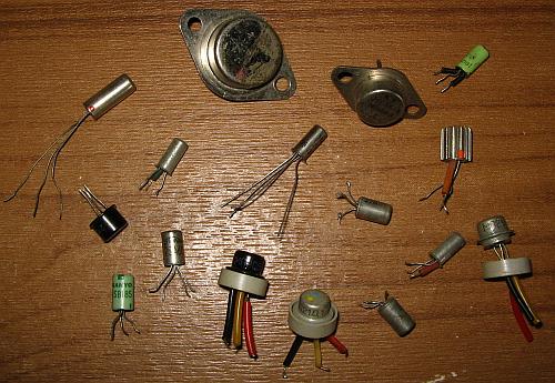
Here you can see a few of the transistors in my treasure chest. The long one
on the upper left is an OC72. The one in the middle, with four long legs, is
an AF137, a very capable (for the time!) RF transistor. The three flying saucer shaped ones,
fitted with insulating spacers, are Russian transistors, despite having the German colors around
their legs. They have cyrillic lettering I cannot understand. The
one with the very short leads near the middle right is the very ubiquituous
AC125. The black one on the left is a 2N526 made by General Electric. That one
is comparatively modern! Those in green plastic sleeves are Japanese, a 2SB185
and a 2SA103. So is the one which has a built-in heatsink, a 2SB189. The type
number is engraved in the heatsink! On top are two power transistors, a 2SB487
and another, totally illegible one.
Many of these transistors had something to
mark the collector lead. A red or orange dot, or a more spaced pin.
Using some of these transistors, and an
assortment of other old parts, such as paper capacitors, carbon composition
resistors, and audio transformers, the AAAA was conceived: An Awfully
Antique Audio Amplifier
! As you will soon see, it has several absolutely special
features, that make it an outstanding audiophile design, in every sense!
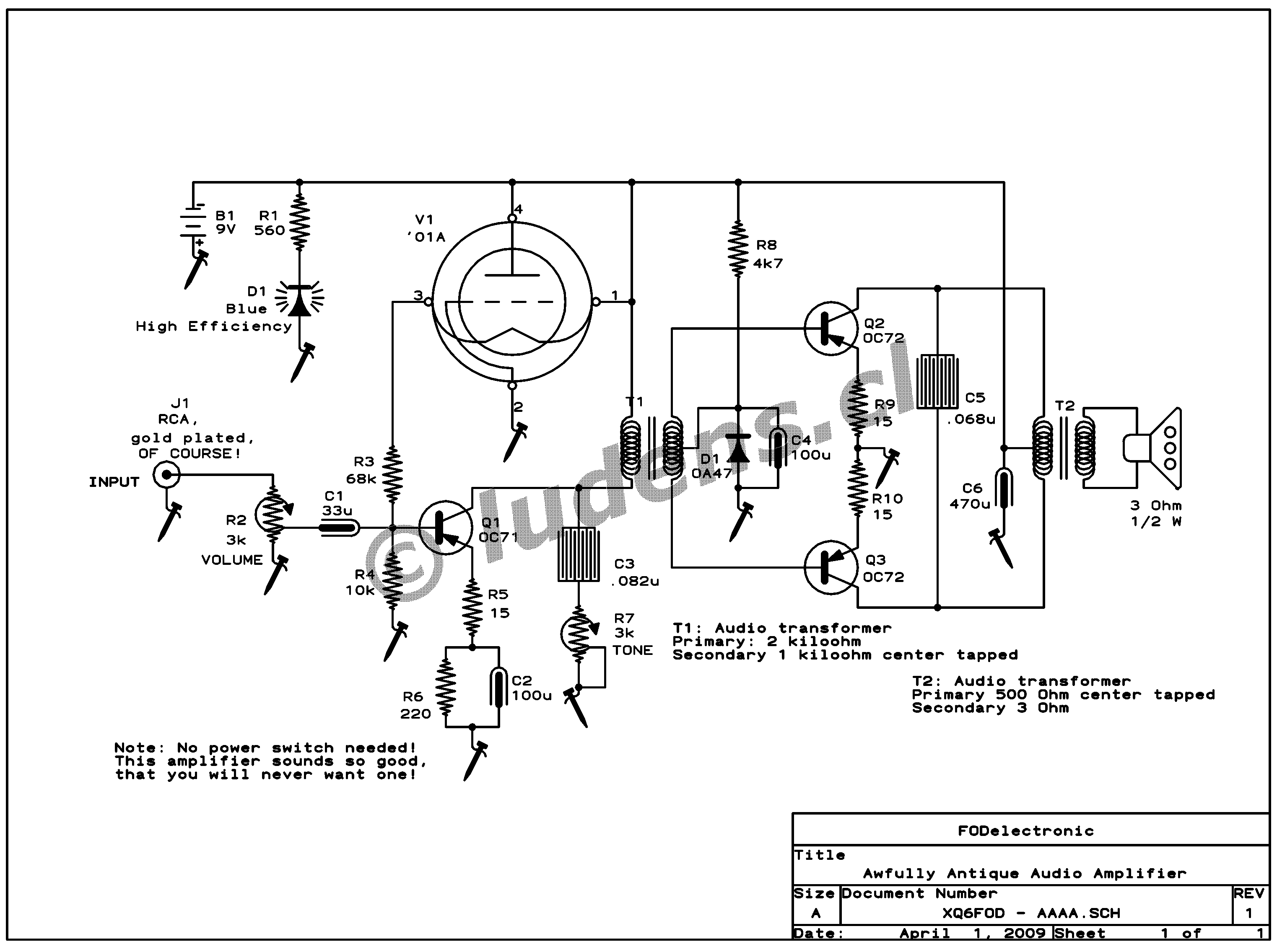
So, here it is, the AAAA, drawn in 20 year old
CAD software, using My Very Own Standard Symbols!
If you really want to print this work of
art, first click the image to get a high resolution version!
Since this is an audiphile amplifier of the
best style, everything starts with a gold plated input connector. Don't skip it!
Nobody who knows anything about audio would ever consider to even listen to an
amplifier that does not use a gold plated input connector!
Anyway, what follows is a standard volume
control and then a driver stage, based on the OC71 transistor. It uses some
emitter degeneration, which was a truly exceptional quality feature in
the glorious days of Germanium - most circuits did without, because
their designers were still thinking tubes.
If you happen to find an OC71 from the
first production years, it will come in a little glass encapsulation, covered
with black paint! That allows a further improvement to this already fine antique
amplifier: Scrape off the paint, then you can use the ambient light to change
the bias of the transistor! If you have fluorescent lamps, the OC71 will then
pick up a very homely hum from them, sounding much like a true valve amplifier!
This hum will give it a few additional audiophile points.
Dangling from the collector is a tone
control network. You know, those things that could be used to strip all higher
frequency components from the signal, or strip only part of them. You can label
the tone control knob with "speech" on the high resistance end, and "music" on
the other side, as was commonly done with radios of the time this amplifier
belongs to! Roughly in the middle of the range you could write "Jazz". After
all, that wasn't music, so it needed a dedicated position between boomy
music and screechy speech.
The power stage uses two legendary OC72
transistors in true push pull, to give a whopping quarter watt output. This
stage too has emitter degeneration, and also it sports diode biasing, making it
very modern within the timeframe of the OC72! Between the collectors is a
capacitor sometimes called "tone condenser" in antique literature. If you are
old enough, you might know: The less treble a radio or audio device had,
and the more boomy the bass was, the better was its "tone"! So the designers
added a capacitor that would short out enough of the high frequency components,
to improve the tone. The bass boominess was best obtained by installing the
speaker in a cabinet that was completely open on the backside. That allowed the
speaker's membrane to vibrate about two centimeters at its resonant frequency.
The lack of negative feedback from the output, in this amplifier, makes its
output impedance very high, so that at the resonance of the speaker there will
be higher output power, further enhancing boominess. Very good tone,
indeed!
Audiophiles with gold-plated ears have
long being talking about a curious thing called transient intermodulation
distortion, an effect that happens when you put a pulse having very
steep flanks, with a frequency spectrum extending far beyond audio, into an
audio amplifier that has large overall negative feedback, large open loop gain,
low speed in some stage, high speed in another, and no low pass filtering. Well,
I can assure you that the AAAA is completely free of TID! It has no overall
negative feedback at all, its gain is lousy low, it's very slow indeed but won't
pass any high frequencies, thanks to these antique Germanium transistors being
real audio devices: By their slow nature, they won't amplify
anything of a much higher frequency! But of course, please don't ask about
harmonic distortion, or static intermodulation distortion... Anyway, they
contribute to the good tone of this amplifier! You know, many audiophiles say
that certain sorts of harmonic distortion sound really good, which is why they
love valves and audio transformers. And the electric guitar fans are yet another
breed, they even use intentional distorters. But let's waste no time on them,
it's a lost cause!
If you have looked very closely at the
schematic, and if you aren't too young to know, you might have noticed a '01A
triode in the driver's biasing circuit. So this is a triode-biased transistor
driver, surely a revolutionary new invention by Yours Truly! And if you are too
young to know what a triode is, well, it's a cylinder made of absolutely
nothing, a few centimeters diameter and maybe twice as long, which has a
delicate structure of wires and sheet metal in its center, and a thin layer of
glass all around. Sometimes instead of a cylinder, the piece of nothing at all
is shaped like a cone with rounded base, or some other fashionable shape. The
whole contraption belongs to the family of empty-state electronic
devices, that was called a "valve" by sophisticated Englishmen, or
simply a "tube" by the plainer people in the USA. They were used
mostly before the OC72 came around. And the '01A is the most famous of the very
basic and most antique mass produced tubes! It has cult status, and so
there is no better thing to use in an audiophile circuit than the '01A.
You say that the tube isn't doing anything
in this circuit? Come on! It's doing something
very important! If you demonstrate this amplifier to any
true audiophile with thickly gold-plated ears, the very fact that there is a
tube in it, and actually a true and real '01A, will make this person hear an
indescriptible delicious quality of sound, which just wouldn't be there if there
was no tube in sight!
And if anybody notices that the tube's
filament doesn't even light, just defy him to pull the tube out of its socket.
The amplifier will immediately stop working, as the OC71 doesn't get any bias
anymore. What better way could there be to show that the tube is indeed
performing an essential task in the amplifier? One important caution is in
order, though: If you implemented the ambient light pickup feature,
by using the glass-encased OC71 with the black paint removed, you must
darken the room for this demonstration, otherwise the transistor will happily
self-bias, and keep running even with the tube removed!
At last, you might ask what an ultramodern,
high efficiency blue LED is doing in an antique circuit like this. Well, it
sets a little accent of eye-catching effect, like the obligatory tiny
highlight in a true low key photograph! And anyway,
using something completely out of place in modern antiques has a long tradition!
Or have you never seen any of those Chinese fake antique cathedral-style radios,
which have a little switch labelled "AM-FM"? Now go and search for a real
antique cathedral radio that receives FM! That would have been alien technology
in their time!
But if the blue LED disturbs your sense of
antique aesthetics, then use an orange LED instead, and make it shine into the
'01A. That way those modern fake audiophiles who have never seen a real tube
will think the filament is lit!
Construction
Don't even consider the use of a printed
circuit board! That would be awfully out of place for an antique amplifier! No,
you have to build this thing on a chassis, the real way. Start obtaining or
building a solid, large and heavy chassis. Cast iron is best, of course. If you
really can't craft it from cast iron, then use some thick steel plates. They
must be cadmium-plated, and forget that cadmium is poisonous and a carcinogen.
It wasn't generally known in the good old time, so it's no problem. If the
whole thing ends up too light, add some lead weights to the underside, and once
again, forget that lead is toxic too! Who cares? You won't eat the AAAA!
Or if you have some large, heavy transformers, install them on the
chassis, no matter that they aren't connected anywhere. Like me, you surely know
enough people who judge the quality of a piece of electronic equipment by its
weight! If they can lift it, it's poor quality. So, let's satisfy them, and make
this thing heavy!
The transistors mount on sockets, on top of
the chassis. The audio transformers also mount on top. The remaining parts are
probably best installed under the chassis, but you might want to add some large
old can-type electrolytic caps on top, for the show effect. The two
potentiometers mount on the front of the chassis, and get large, knurled
bakelite knobs with a little gold-plated insert in the middle. And of course,
the tube goes in the exact center of the chassis, with one mirror behind it, and
another two mirrors to its sides, forming angles of about 120 degrees with the
rear mirror. Don't dare to skip these mirrors! They add a lot of audiophile
appeal to the amp!
And yes, the chassis has to be painted glossy
black. Use gold-plated trim stock around the edges, and for the mirror
frames.
The transistors and transformers have to
be arranged in a nice symmetrical way around the tube. The aesthetics
count. Don't worry about wire lengths. Just be sure to use oxygen-free copper
cable for them, and all will be fine. Oh, I almost forgot: Real top quality
ultra pure HiFi solder is a basic requirement, of course!
Finding a suitable name
The hardest part about crafting a fine
antique like this, is finding a suiting name for it. For this article, I decided
in favor of AAAA, meaning Awfully Antique Audio Amplifier, which I hope
you have noticed already. Yet that wasn't the original name! It started as the
Antique Hybrid Amplifier, or, for short, the AHA! Then it morphed
into the High-quality Antique Hybrid Amplifier, or
HAHA... But I soon figured out, clever me, that any "H" in the name
wasn't convenient. Several A's in a string are better, because this will
guarantee that the amplifier will show up first place in any alphabetically
sorted list, and that's an important feature, because anyway most people don't
look down a list further than the first entry! That's how this amplifier came to
be called the AAAA.
Depending on upcoming competing designs, I
might have to change the name, to assure continued permanence at pole
position. So this amplifier might end up named the AAAAAA, or in full text,
the Absolutely Awful Audiophile April Audio Amplifier!