Understanding, fixing and improving the LC100-A inductance
& capacitance meter
 Maybe
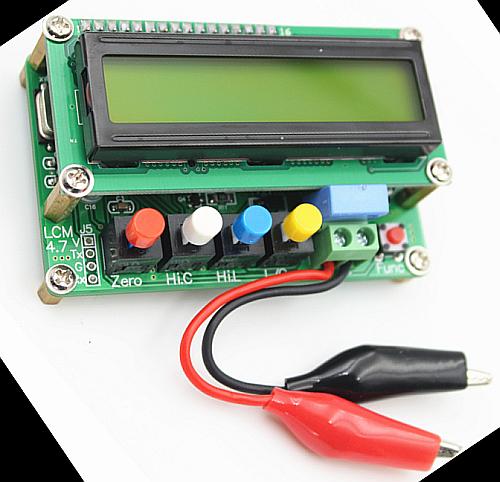
this has happened to you: Browsing the web, you stumble upon some offer
for a device, instrument, toy, whatever, that seems too good to let it
pass - and you buy it, just in case it's any good. This happened to me
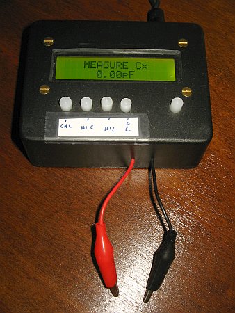
when I stumbled upon the LC100-A inductance and capacitance meter,
which is sold on many websites all over the world, and is shown here in
a photo taken from one of those websites.
Maybe
this has happened to you: Browsing the web, you stumble upon some offer
for a device, instrument, toy, whatever, that seems too good to let it
pass - and you buy it, just in case it's any good. This happened to me
when I stumbled upon the LC100-A inductance and capacitance meter,
which is sold on many websites all over the world, and is shown here in
a photo taken from one of those websites.
The manual claims pretty good specs: A measurement range of
0.01pF
to 100mF (yes, that's 100,000µF), 1nH to
100H, 1%
accuracy from 1pF to 1µF and from 1µH to 1H, and 5% accuracy outside
those ranges. All that for just US$11, including fully trackable
international AliExpress Standard Shipping! Sounds
definitely too good to be true, but at the same time very tempting, and
promising some entertainment for little money. If it actually works
well enough, it can be a worthwhile addition to my workbench, because
while I do have two multimeters that do a good job measuring
capacitors, I don't have another inductance meter that's quick and
comfortable to use. So I bought this LC100-A.
As soon as I got it, I tested it on a wide assortment of
capacitors
and inductors, measuring the capacitors also on both of my multimeters.
Surprise! The typical accuracy of this meter, on many
components,
was more like -15%, far from the claimed ±1%. Well, can we really call
that a surprise?
This instrument has four ranges. Low C is supposed to measure
up to
10µF, high C is for capacitances from 1µF upwards, low L is for
inductors up to 100mH, and high L for inductors from 1mH upwards. So I
set out to try each of the four ranges.
The high C range worked pretty well. Low C tended to be about
15%
low over much of the range, getting better at values of around
200nF, and then measuring ridiculously high beyond that, like reading
over 8µF for a 2.2µF 5% film capacitor.
The low L ranges tended to read about as low as the low C
range,
with the high L range being much closer to the real values. When
measuring inductors it's important to keep in mind that this meter uses
a variable test frequency of up to several hundred kilohertz, and many
inductors
made for lower frequencies use magnetic cores that don't work well at
the higher frequencies. This is not a fault of the instrument, and
after noticing this I only used test inductors that have a stable
value up to at least 1MHz.
Another problem was that the switches showed unstable contact
resistance. Pressing and releasing a switch would make the meter show a
very different value! Even slightly wiggling the L/C switch's button,
without actually pressing it, would make the measured value change a
lot.
In all ranges except high C it was critical to use the zeroing
function quite often, since the instrument showed drift that caused
severe measurement error when it had not been zeroed for a few minutes.
This sort of drift is to be expected in a low cost instrument, but the
inability of getting anything better than 15% accuracy over most of its
range meant that the instrument was almost worthless. So I decided to
reverse-engineer it, just for fun, and to see if it could be fixed.
Fixing the switches
The first step was disassembling the four switches, cleaning
their
contacts with DeOxIt concentrated contact cleaner, then rinsing them
out with isopropyl alcohol, then applying a layer of DeOxIt Shield to
keep the contacts from oxydizing again too quickly, and reassembling
them. After this job, which isn't hard to do but requires some
dexterity and
patience, the switch instability was gone. But the underlying problem
is that the factory used switches that have power-type contacts, rather
than small-signal contacts. The gold plating required on small-signal
contacts probably makes switches too expensive to be used on an $11
meter.
Update! The switch contact problem returned after just a few weeks...
Then I set out to reverse-engineer the circuit, so I could understand
it, and see why it worked so poorly. I didn't try to get into the
software running on the meter, concentrating my efforts on the
hardware. The reason is that the software is probably correct in its
mathematical operation, and the problems are typically caused by bad
decisions when selecting components at the factory. These meters are
apparently made by several different factories, and some are better
than others.
How the LC100-A works
This meter contains two completely separate measurement circuits. One
is used just for the high C range, while the other is used for the
other three ranges. A microcontroller does the required maths and
presents
the results on the display.
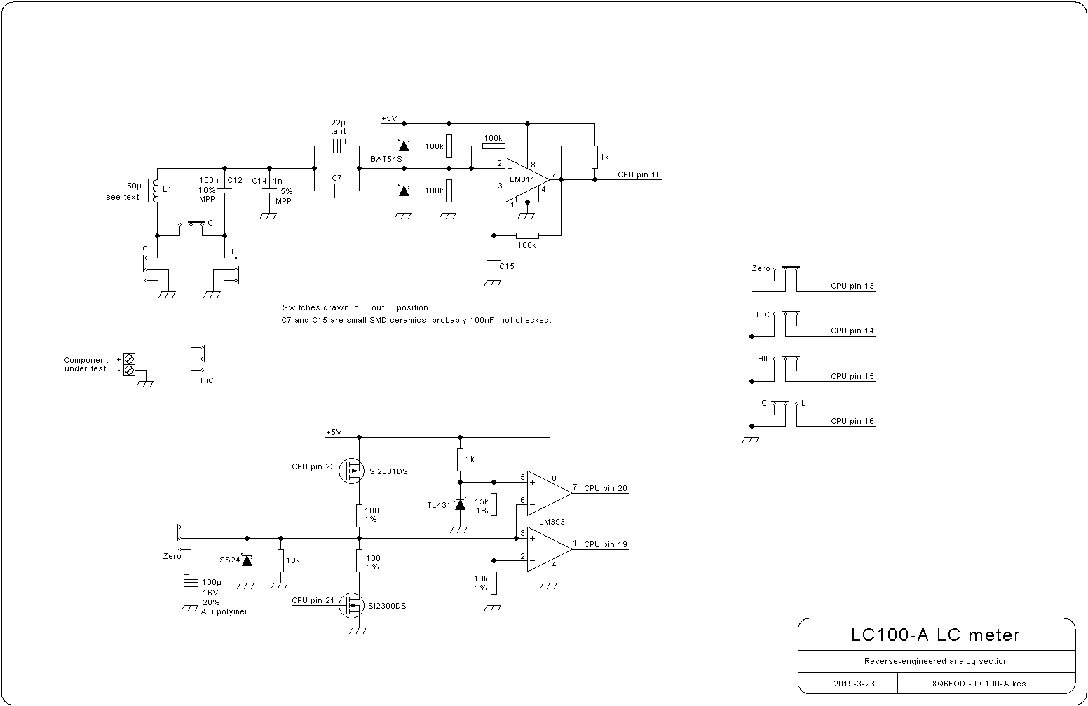
So let's start with the main measurement circuit.
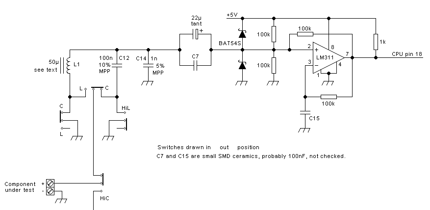 This
is an LC oscillator, whose frequency is controlled by three internal
components (L1, C12, C14) and the component being measured. These four
parts form a parallel resonant circuit.
This
is an LC oscillator, whose frequency is controlled by three internal
components (L1, C12, C14) and the component being measured. These four
parts form a parallel resonant circuit.
In low C range, L1's low end is grounded, C14 is in parallel, and the
capacitor being measured is connected in series with C12, this
combination being connected in parallel to C14. So the resonant circuit
has a fixed inductance of L1, and a capacitance that varies from 1nF
when the test leads are open, to 101nF when they are shorted, and very
close to 101nF when a large capacitor is connected. The
resulting resonant frequency range is then about 700kHz with the test
leads open, down to around 70kHz when they are shorted, but these
values depend on the actual value of L1, which can vary a lot from one
sample to another.
When pressing the "Zero" button, the CPU will measure the
frequency, and assuming a 1nF capacitance, will calculate the value of
L1. When you then connect a capacitor to the test leads, the CPU will
measure the new frequency, and since it knows the values of L1, C12 and
C14, it can calculate the value of the external capacitor.
In the low L range, C12 is not used, and the inductor being measured
connects in series with L1, that combination being in parallel with
C14. The operation logic is the same as in the low C range. And in the
high L range, the only difference is that C12 is added in parallel
with C14, so now the capacitance of the resonant circuit is 101nF, the
free-running frequency (test leads shorted) is around 70kHz, and the
lowest frequency with the highest suppported inductor connected
is 50Hz.
Let's now look at the rest of the oscillator: The 22µF tantalum
capacitor
in parallel with a ceramic chip couples the resonant circuit to the
comparator, which is configured in such a way that the DC bias on its
positive input is 2.5V, and in the absence of any oscillation in the
resonant circuit it will oscillate at a low frequency, given mainly by
the value of C15 along with its 100kΩ resistor. The switching
transitions will excite the resonant circuit, and the oscillator will
then fall into an operating mode where C15 and its resistor provide a
DC bias on pin 3 that follows what pin 2 gets, so that the output
squarewave will achieve a roughly 50% duty cycle. The oscillation of
the resonant circuit basically switches the comparator, which provides
a weak positive feedback via the 100kΩ resistor from its output to pin
2 and thus the resonant circuit.
So the oscillation amplitude on the resonant circuit will build up
relatively slowly, and finally become limited by the two Schottky
diodes clipping it to a peak-to-peak value of about 5.4V.
It's interesting to realize that the comparator and its associated
resistors load the resonant circuit with roughly 30kΩ. At
700kHz
the resonant circuit has a reactance of about 230Ω in each leg, so that
the loaded Q would be around 130. In practice it's surely a little
lower, due to the losses of L1. On the other end of the scale, with
100mH connected externally in the low L range, the loaded Q is only 3!
That's why the circuit requires switching into high L range, adding the
other capacitor, to bring the loaded Q back up and allow measuring even
higher inductances.
Note that C7 is probably not necessary at all. With the oscillator
circuit loading the resonant circuit at 30kΩ, I find it highly unlikely
that a 22µF tantalum capacitor might have enough series inductance or
resistance to be significant and require shorting by a ceramic cap.
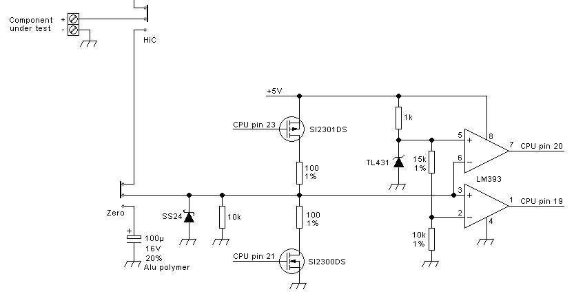 The
circuit for the high C range is totally different. It charges and
discharges the capacitor under test, through 100Ω resistors controlled
by MOSFETs, and measures the time needed to move between two fixed
voltages. The TL431 provides a 2.5V reference, which sets the upper
voltage level, and a resistive divider creates the lower level of 1.0V.
The two
comparators change their output states when the capacitor
voltage
crosses these levels.
The
circuit for the high C range is totally different. It charges and
discharges the capacitor under test, through 100Ω resistors controlled
by MOSFETs, and measures the time needed to move between two fixed
voltages. The TL431 provides a 2.5V reference, which sets the upper
voltage level, and a resistive divider creates the lower level of 1.0V.
The two
comparators change their output states when the capacitor
voltage
crosses these levels.
Note that the time needed to charge from 1V to 2.5V depends on the
supply voltage, so this is not a useful parameter to measure, except if
the supply voltage is well regulated - and it isn't in this instrument,
given the lack of a local voltage regulator. Instead the
discharge time from 2.5V to 1V is independent from the supply voltage,
so I guess (and hope!!!) that this is the time the software uses to
compute the capacitance.
The operation of this circuit might be like this: The CPU switches on
the upper MOSFET, waits until the capacitor has charged to 2.5V as
sensed on pin 20, waits
a little more, then switches off the upper MOSFET and switches on the
lower one. Then it measures the time from the instant the capacitor
voltage crosses 2.5V until it crosses 1V, through the transitions of
pins 20 and 19, and calculates capacitance
from it. Then it repeats the cycle.
The SS24 Schottky diode protects the circuit in case somebody connects
a charged capacitor with reversed polarity. But if anybody connects a
capacitor charged to more than 5V, with correct polarity, it would be
easy to blow up the LM393. The manual properly warns
against doing this.
Given the 1% resistors, and the pretty accurate TL431, such a circuit
could be used without any calibration. It would certainly produce an
accuracy within a few percent. And of course it needs no zero
calibration, since zero capacitance causes zero time to be measured,
and stray capacitances are insignificant relative to the capacitance
values this circuit measures. But this
circuit does include a reference capacitor, and when pressing the
"zero" button, it actually does a scale calibration. I was
shocked to see that the calibration reference capacitor is an
aluminium polymer capacitor having a ±20% tolerance specification!
Using that is worse than not calibrating at all! But then I measured
that little capacitor, and was profoundly surprised to find its actual
value to be within 0.3% of the nominal one! I don't know
whether
they cherry-pick capacitors for this position from a big batch, or if
this was pure luck, or if all these polymer capacitors are so very much
more accurate than their specs say. Such are the adventures of
reverse-engineering!
I have seen photos of other versions of the LC100-A using a tantalum
capacitor for calibration. I don't know if that would be better or
worse. But in my specimen this high C measurement circuit works well,
so I left it
alone, and devoted my further efforts to the main measurement circuit.
Fixing the problems
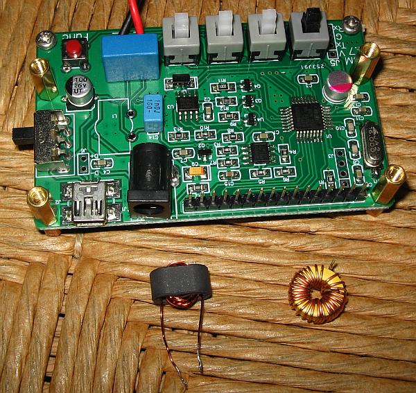 My
LC100-A came with a powdered iron toroid as the core for L1. It is a
yellow core with one white face, which is the usual color-coding for
lowest quality, cheapest, high permeability, hidrogen-reduced iron.
These cores
are massively used for filter chokes in switching power supplies, and
do a great job there, at frequencies up to a few tens of kilohertz. But
using such a core as a critical element in a high precision test
instrument operating at frequencies close to 1MHz, is gross
nonsense! It will change its inductance as the frequency
swings
from 700kHz downward, thoroughly messing up the calculations done in
the CPU!
My
LC100-A came with a powdered iron toroid as the core for L1. It is a
yellow core with one white face, which is the usual color-coding for
lowest quality, cheapest, high permeability, hidrogen-reduced iron.
These cores
are massively used for filter chokes in switching power supplies, and
do a great job there, at frequencies up to a few tens of kilohertz. But
using such a core as a critical element in a high precision test
instrument operating at frequencies close to 1MHz, is gross
nonsense! It will change its inductance as the frequency
swings
from 700kHz downward, thoroughly messing up the calculations done in
the CPU!
Photos on the web show that many LC100-A meters, specially older ones,
came with a twin-hole ferrite core instead. And in fact the
silkscreen marking on the PCB shows exactly that core shape, not a
toroid! So
it is obvious that the original specification was for such a twin-hole
ferrite core, and definitely not for a high-permeability powdered-iron
toroid!
From web photos, and the silkscreen printing, it was easy enough to
determine the size of the correct core. What I don't know is what exact
material it should be made from. There are many different
kinds of
ferrite, with dramatically different characteristics. Anyway, in my
parts stock I had this size of core in only two different types of
ferrite: Those having permeabilities of 125 and 850.
Among these two, the 125-permeability material is far more stable, both
against frequency changes and temperature changes, so I used that one.
I calculated that I needed 18 turns to get close to the same inductance
the original toroidal coil has (44µH), and my worry was how to get the exact
correct value, given
that adding or removing a single turn would already change the
inductance by more than 10%! So I wound 20 turns, as a first try,
planning to remove turns as necessary.
I wound my coil, soldered it into the circuit and tried.
Voilá,
now my LC100-A was almost totally precise! A 300pF 2.5% precision
capacitor measured as 299.7pF, a 1000pF 2% silver mica displayed
1001pF, and so on! Only the higher capacitance values, from several
tens of nanofarad upwards, showed increasing error.
Main problem solved! But this smelled strange: How could my 20 turns on
a core selected on very windy reasons have ended up with precisely the
right inductance? To find out, I wound another of those cores, with 22
turns. The results were the same, in terms of accuracy, although the
oscillation frequency was lower. That's how I learned that this meter
does not need a precise inductance at all for L1! All it needs is an
inductance that remains stable, while the frequency changes a lot. The
"zero" function will calculate the actual inductance value of L1 and
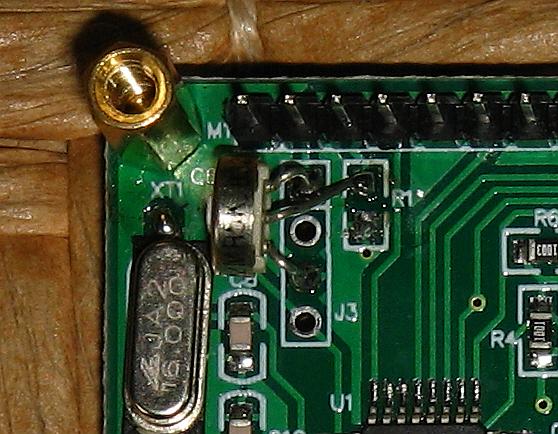
use it, regardless what it is, within some reasonable limits.
I kept the coil with the 20 turns, which gave an inductance of 97µH, and hot-glued it to the circuit
board for better stability. The yellow toroid fitted by the
excessively cost-conscious Chinese factory went into my junk box, to be
used
in one of my next switching voltage regulators.
By the way, the exact core I used is a Ferronics 12-360-K.
 Then
I turned to the persisting problem of increasing measurement error as
the capacitance got larger. This is quite obvious: The capacitor to be
measured is connected in series with C12, a 100nF capacitor. So, if the
external capacitor is very small, it dominates the value of the series
combination, and any deviation of C12 is irrelevant. But as the
external capacitance gets larger, C12's tolerance becomes more
important. When the external capacitor is 100nF, any imprecision of C12
will show up as the same imprecision on the measured value. And if the
external capacitor becomes large, like a few microfarad, then C12
totally dominates, and even a small imprecision of C12 causes a huge
error in the measured value! This is what was happening.
Then
I turned to the persisting problem of increasing measurement error as
the capacitance got larger. This is quite obvious: The capacitor to be
measured is connected in series with C12, a 100nF capacitor. So, if the
external capacitor is very small, it dominates the value of the series
combination, and any deviation of C12 is irrelevant. But as the
external capacitance gets larger, C12's tolerance becomes more
important. When the external capacitor is 100nF, any imprecision of C12
will show up as the same imprecision on the measured value. And if the
external capacitor becomes large, like a few microfarad, then C12
totally dominates, and even a small imprecision of C12 causes a huge
error in the measured value! This is what was happening.
In my LC100-A, the factory chose a 10% tolerance, X-type (275V
AC rated)
polypropylene capacitor. Go figure why they did this! These are
designed for safety and high voltage, and definitely not for high
accuracy! It turns out that mine was about 3% high, so it was very well
within its 10% rating, but far too imprecise to be used in this
circuit. C12 needs to be super-precise, if we want the LC100-A to give
halfways reasonable readings for capacitors of a few microfarad, in the
low C range!
Every electronician with some years of activity has hundreds of
assorted 100nF
capacitors in his parts stock. So it was not hard to find one that
measured slightly lower than 100nF on my multimeters, and which showed
a very good thermal stability. I took that one, and soldered it into
the circuit, in place of the original big blue X capacitor.
As expected, with that slightly low value, now the readings for
capacitors of a few microfard were very low. Like one half the correct
value, or -50%!
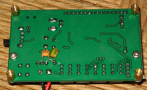 I
then added another capacitor in parallel to C12, to bring the total
value as close as possible to 100nF, while still staying below it. This
turned out to be a 2.2nF capacitor. With that in place, the readings
for my test capacitors in the several-µF-range were much better, but
still not good enough. So I added yet another capacitor in parallel, a
560pF one, which brought the total value close enough to 100nF so that
now a 4.7µF film capacitor, which measures 4.935µF on one multimeter
and 4.94µF on the other, measures 4.93µF on my LC100-A. Close enough.
Case closed.
I
then added another capacitor in parallel to C12, to bring the total
value as close as possible to 100nF, while still staying below it. This
turned out to be a 2.2nF capacitor. With that in place, the readings
for my test capacitors in the several-µF-range were much better, but
still not good enough. So I added yet another capacitor in parallel, a
560pF one, which brought the total value close enough to 100nF so that
now a 4.7µF film capacitor, which measures 4.935µF on one multimeter
and 4.94µF on the other, measures 4.93µF on my LC100-A. Close enough.
Case closed.
If you need to do this sort of adjustment yourself, and you don't have
another capacitance meter, nor precision reference capacitors in a
suitable range, here is a great
trick to find out whether your C12 is precise or not: Take any two
capacitors having values anywhere in the range of 220nF to 470nF or so.
Measure each of them separately on the LC100-A, then measure both in
parallel. Of course, the value measured for both in parallel should be
identical to the sum of the individual values. If this happens, your
C12 is fine. If instead the value measured for the parallel capacitors
is very different from the sum of their individual measurements, your
C12 is inaccurate, and requires correcting!
I would like to point out that you need to be extremely careful to
properly zero the instrument while doing these measurements, because
measuring such relatively high value capacitors in the low C range is
as sensitive to the value of L1, as it is to that of C12! If the coil
drifts by just 0.1% between the last zeroing and your measurement, the
value measured for a capacitor much above 100nF will be very wrong.
Of course this circuit is misdesigned, or rather let me say that it's
unrealistic to measure a big capacitor in series with a much smaller
internal one. Really the low C range of the LC100-A should have been
limited to a maximum reading of 100nF, or at the very most 1µF, but
never 10µF. Or a different circuit should have been used, in which the
capacitor being measured is not in series with an internal one.
While I was busy adjusting C12, I also removed C14 to check its value.
This is a 5% rated capacitor in my sample, and measured highly precise
on my multimeters, well within 1%, so I left it in place. I suspect the
factory cherry-picked it, like the 100µF calibration capacitor, and
that's a good thing. Or it was just luck.
Note that it would be perfectly possible to use any capacitors for C12
and C14, having inaccurate values, as long as they are stable, and
measure them at production time and program the actual values into the
software. But I doubt that the factory does this. If they do, they
didn't do it correctly with my C12.
Two
readers of these page have contacted me to comment that their LC100-A
meters allow software-calibration of the capacitor value, by using
the calibration function with the terminals shorted instead of
open, in low capacitance mode. Apparently doing several iterations of
shorted and open calibrations makes their meters learn the actual
values of both L1 and C12. I could not observe this behavior
on my meter in any certain way. Calibrating low C with the terminals
shorted at some times does not seem to make any change in mine, while
at other times it seems to make a change, but not achieving a good
calibration. Maybe different manufacturers use slightly different
firmware, despite them all displaying "Rev4.8" at start! Or maybe the
unstable contact resistance of the switches in my meter obfuscate the
results.
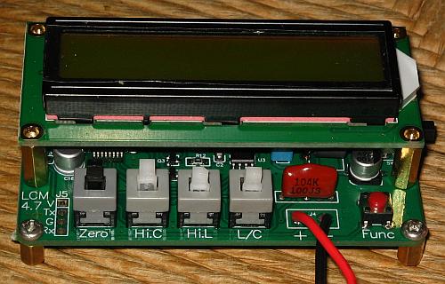
Contrast
 The
kind of liquid crystal display used in this meter has an input pin to
adjust the
contrast. The contrast needs to be set individually, due to
manufacturing tolerances, supply voltage, temperature, etc. But the
money-savers at the factory decided to NOT provide an adjustment, and
instead install a fixed resistor. Probably the display on their test
bench gave excellent contrast with that resistance value - but not the
one they sold me! It was showing the characters
in black on a nearly black background, and was very hard to read.
The
kind of liquid crystal display used in this meter has an input pin to
adjust the
contrast. The contrast needs to be set individually, due to
manufacturing tolerances, supply voltage, temperature, etc. But the
money-savers at the factory decided to NOT provide an adjustment, and
instead install a fixed resistor. Probably the display on their test
bench gave excellent contrast with that resistance value - but not the
one they sold me! It was showing the characters
in black on a nearly black background, and was very hard to read.
I'm not the only one having that problem. I found the website of
VK4GHZ, who gives nice instructions for the installation of a
potentiometer. Instead of re-inventing the wheel, I used his wheel...
Just that I had only a few 10kΩ potentiometers, none of them small
enough, but a bag full of 5kΩ ones, so I used one of those.
Another small change I made, visible in the photos above, is that I
removed the screw terminal block, and soldered the test leads directly
to the board.
Using this meter
After all the modifications, my LC100-A now works pretty well. Well
enough, in fact, that I might actually put it into a nice black plastic
project box and add a 7805 regulator! But that can wait... there are
more important projects waiting.
 Update! I did put it in that box!
It's important to use the "zero" function frequently, basically before
every measurement. It's not necessary to save the values every time -
waiting for the "OK" displaying is enough. This is for the low C and
both L ranges. The high C range doesn't need frequent
calibration.
When measuring capacitors, a good changeover point between low and high
range is about 0.2 to 0.5µF.
When measuring power supply inductors, it's often good to use
the "high"
range, so the meter uses a 10 times lower frequency, which is usually
much closer to the intended operating frequency of those inductors. If
the resolution in that range is not enough, you can use the "function"
button to see the oscillation frequency, one time with the leads
shorted and then with your inductor connected. Then you can do the
maths yourself, and calculate the inductance with higher resolution.
Also be sure to always check the oscillation frequency, when measuring
inductors that have cores unsuitable for RF. If the LC100-A is using a
frequency much higher than the frequency the inductor is made for, do
not trust the reading. While the reading is probably correct, it's
valid at that high frequency, and the coil's inductance at the
frequency of your power supply is probably a lot higher! This is the
main limitation in the usability of this meter.
Final thought
Chinese gadgets are just great. How else could you get several days of
entertainment and education for just 11 dollars, ending up with an LC
meter that actually works?
Back to homo ludens electronicus.