Mechanical construction
The lathe I used is a small German-made desktop unit intended for hobby
use, that can turn pieces up to 75mm diameter and about 250mm length. I
bought this lathe with the specific idea of finally being able to build
a good mobile antenna, and other radio-related mechanics! I learned the
basics of tooling operations while building this antenna.
The loading coil:
 There are several
advantages to winding the loading coil inside the support tube:
It will be protected from the weather and dirt, it will look clean, and
it will allow all of the tuning mechanisms to use the room inside while
contacting the wire. So I had to come up with a way of making such a coil!
And it needs to be quite precise, because the wheels of the chariot must
be able to freely run on the coil turns, without ever causing a short between
two turns!
There are several
advantages to winding the loading coil inside the support tube:
It will be protected from the weather and dirt, it will look clean, and
it will allow all of the tuning mechanisms to use the room inside while
contacting the wire. So I had to come up with a way of making such a coil!
And it needs to be quite precise, because the wheels of the chariot must
be able to freely run on the coil turns, without ever causing a short between
two turns!
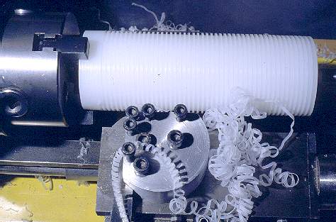
I first made a winding core from inexpensive, soft polyethylene (PE).
This core has a diameter of 55mm, which is 2mm less than the internal diameter
of the coil tube. The core is slightly longer than the coil tube; the exact
length is not critical. Into this core I cut a thread, which has a pitch
of 3mm per turn, while the cross section is rectangular. The width of the
cut is 0.1mm more than the wire diameter, so that the wire can move freely
in the thread, and the depth is equivalent to the wire diameter.
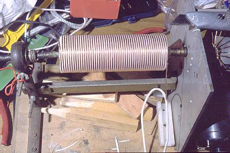 Then
I wound the coil on this core. I used a winding machine I got from CE5FSB,
back in my university times, but hand winding could also have been used.
The wire is the kind used for electrical installations in homes. It's solid
copper wire of 2.5mm² cross sectional area, insulated in PVC. I removed
the insulation while winding, by slitting it open with a sharp knife. It's
good to avoid touching the bare wire, because the skin oils would later
weaken the bond with the glue used to mount the coil in the tube.
Then
I wound the coil on this core. I used a winding machine I got from CE5FSB,
back in my university times, but hand winding could also have been used.
The wire is the kind used for electrical installations in homes. It's solid
copper wire of 2.5mm² cross sectional area, insulated in PVC. I removed
the insulation while winding, by slitting it open with a sharp knife. It's
good to avoid touching the bare wire, because the skin oils would later
weaken the bond with the glue used to mount the coil in the tube.
The wire ends are fixed to the core using two screws installed in the
two ends of the core.
After machining the coil tube, making its two threads, the coil has
to be installed inside. This is done with slow-setting epoxy glue (I used
90-minute Araldite), in this way: Firstly, the tube is sanded on the inside,
using coarse sandpaper, in order to improve adhesion of the epoxy glue.
A layer of epoxy is applied to the inside of the tube. This layer should
be 0.2mm thick. If it's thinner, the structure will end up weaker, and
if it's much thicker, the epoxy will hinder the free motion of the chariot
wheels. I made a spatula of plastic scraps, which has the blade cut to
the exact radius of the glue layer (28.3mm), and covers about 90 degrees
of the tube. This spatula has two little holes at the corners, in which
I anchored small pieces of 0.2mm magnet wire. These serve as spacers between
the spatula and the tube, making it very easy to apply the required even
layer of glue.
 Then
four pieces of 1mm magnet wire were inserted into the tube at 90 degrees
from each other, and bent over the ends of the tube. These four wires serve
as spacers, allowing to slide the core with the coil into the tube, without
touching the glue! Now, from each end of the assembly, 4 small pieces of
spacing wire are inserted. These wires keep the core and coil centered
while the long spacing wires are pulled out.
Then
four pieces of 1mm magnet wire were inserted into the tube at 90 degrees
from each other, and bent over the ends of the tube. These four wires serve
as spacers, allowing to slide the core with the coil into the tube, without
touching the glue! Now, from each end of the assembly, 4 small pieces of
spacing wire are inserted. These wires keep the core and coil centered
while the long spacing wires are pulled out.
The anchorings of the coil wire at the ends of the core are now removed,
and the wire is cut off cleanly, so that it can retreat in the thread of
the core. If all is correct, the coil will spring open and contact the
glue, while being held at the precise pitch by the edges of the rectangular
thread of the core! The low friction of PE helps making this step easy!
In any case, you can help by pushing the coil wire ends in. It's important
that the coil springs open to the full inner diameter of the tube, because
otherwise the chariot may jam later.
During this procedure of settling the coil against the tube, the
short spacer wires are kept in position by adhesive tape or other means.
It's very important to keep the core well centered at all times, because
otherwise it may bind to the glue. While PE does not adhere well to epoxy
glue, you may still manage to get enough glue on it to cause trouble, so
be careful!
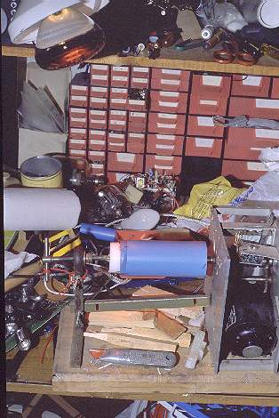
After the coil has fully expanded, the glue should be allowed to set
while the assembly is constantly rotating. This is necessary in order to
avoid the risk of having the glue flow down by gravity, causing an uneven
layer and later trouble. As shown in this photo, I used the winding machine
at low speed, and directed the beam of an infrared lamp on the coil tube,
in order to speed up the setting of the glue.
Excuse me for the messy photo. I surely may win some "messy shack contest"!
 When the glue
has fully set, it's time to remove the core. This is the moment when it's
most important that the core was made from slippery PE, and that the thread
was wide enough: Because the core must be literally screwed out of the
coil! I clamped the core end in a vise and turned the coil tube with both
hands.
When the glue
has fully set, it's time to remove the core. This is the moment when it's
most important that the core was made from slippery PE, and that the thread
was wide enough: Because the core must be literally screwed out of the
coil! I clamped the core end in a vise and turned the coil tube with both
hands.
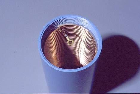
After the core has come out, you can inspect your coil. Wow! Mine came
out looking much better than I had expected!
This photo shows the top end of the loading coil. Any excess wire is
removed, then the last quarter turn of wire is reinforced with additional
epoxy on the top side (no wheel will travel here), the wire end is bent
to fit the plan, and a solder lug is installed. The lug must be centered,
and flush with the end of the tube.
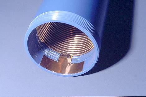 Likewise, the
lower end of the coil is cut to the dimension given in the plan, and then
reinforced with a dab of glue. A contact plate made from 0.1mm copper sheet
is soldered to the last turn of the coil and epoxied to the tube. If part
of a turn remains unused, that's no problem, but make sure that the coil
has the full dimension (amount of turns) shown in the plan! Even one missing
turn would cut off a large part from the 40 meter band!
Likewise, the
lower end of the coil is cut to the dimension given in the plan, and then
reinforced with a dab of glue. A contact plate made from 0.1mm copper sheet
is soldered to the last turn of the coil and epoxied to the tube. If part
of a turn remains unused, that's no problem, but make sure that the coil
has the full dimension (amount of turns) shown in the plan! Even one missing
turn would cut off a large part from the 40 meter band!
Previous page
Next page