My little paradise has a stream that provides enough water flow and head to run a small turbine, to provide electricity to my home. While writing this, the microhydro plant is being implemented, and here are some photos of the process.
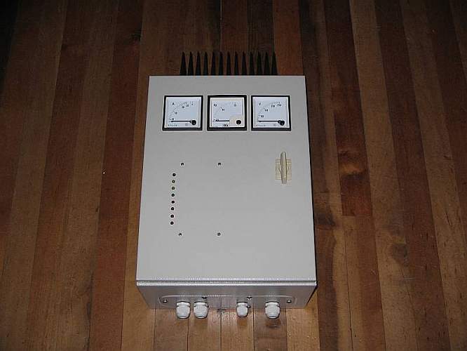
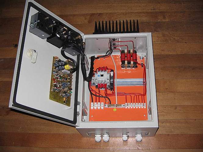
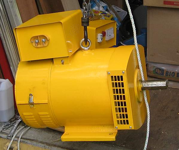
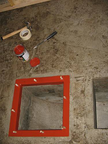
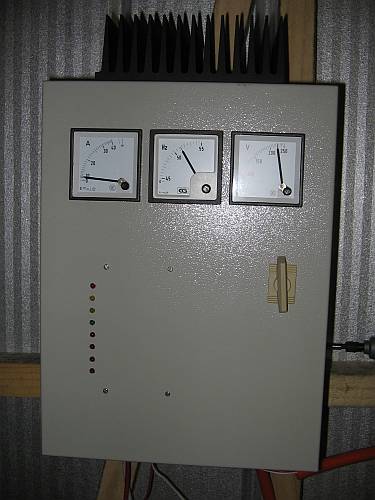
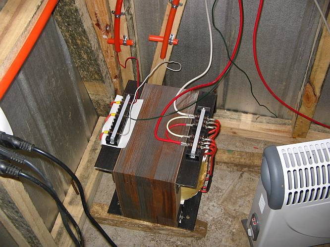
Since I usually like to start at the end, the first thing I built is the controller:
It is an implementation of Jan Portegijs' "Humming Bird", with
some changes and adaptations.
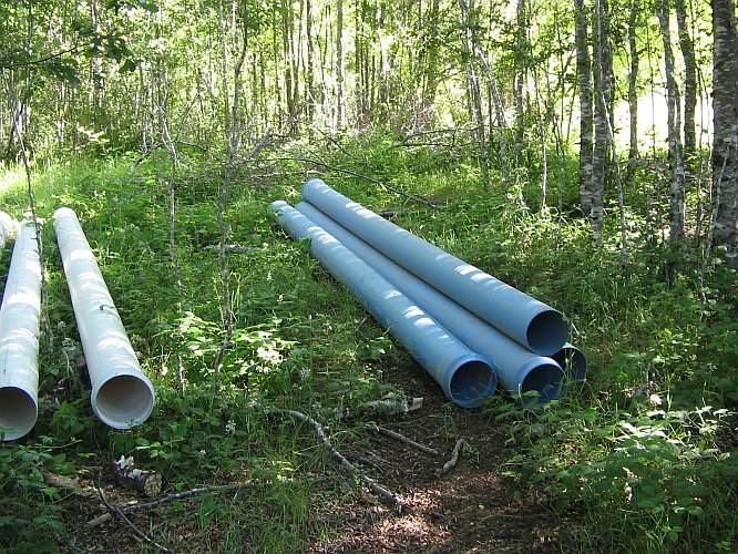
The largest cost of the plant, by far, is in the piping for the rather long penstock. When the purchase was made and the truck arrived, we unloaded the pipes at different places, to get them as close to the installation area as possible. Here are the main stacks:
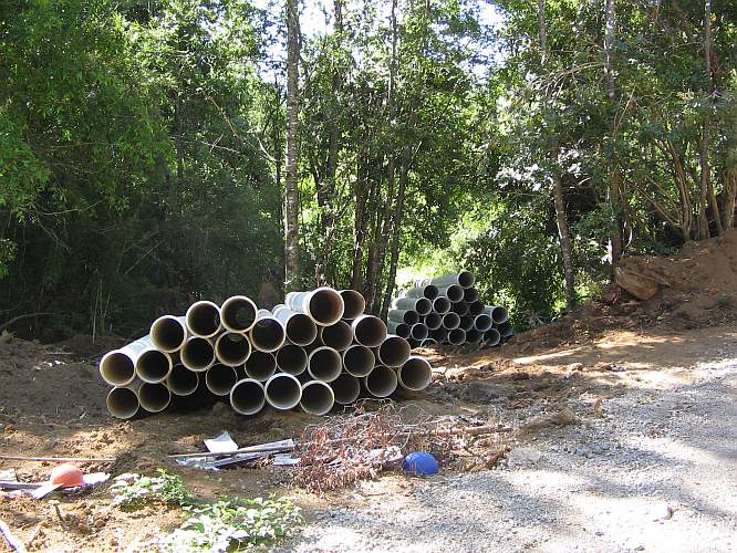
A smaller number of pipes were stored closer to the turbine site. All these are white PVC pipes, class 2.5. The lowest of them will be used pretty much at their safe limit, very close to 2 bar of pressure.
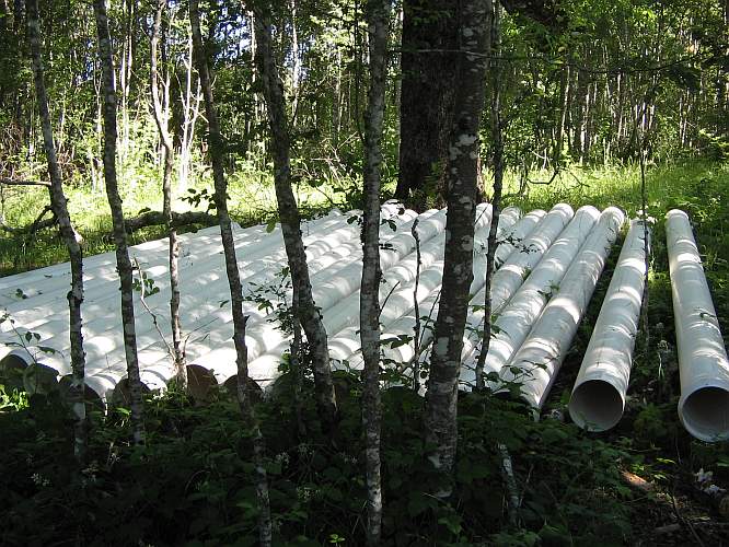
Only for the last part of the run, where the pressure exceeds 2 bar, I will use blue class 4 PVC pipe.
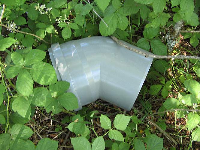
To change from the low slope run of the white pipe to the much steeper run of the blue one, a change of direction is required. I tried to purchase a 135 degrees bent pipe, but it was not available despite appearing in the catalog. The best I could buy is a 135 degrees corner piece, which is far from optimal, but perhaps better than heat-bending a pipe myself, in this relatively high pressure area.
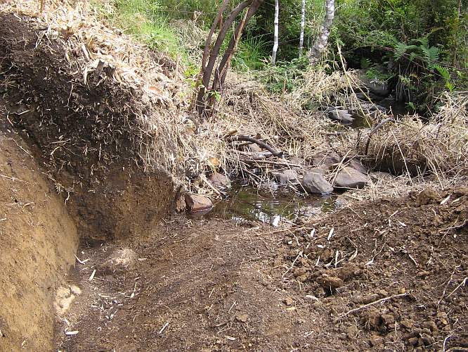
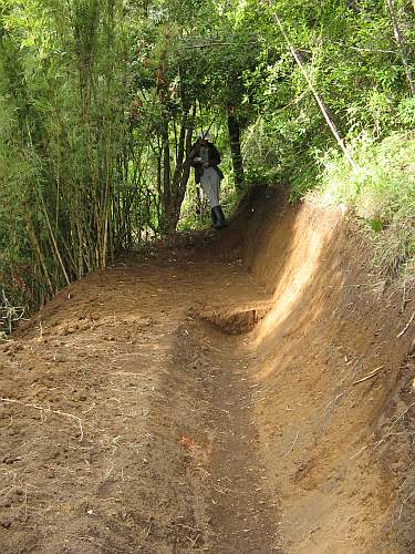
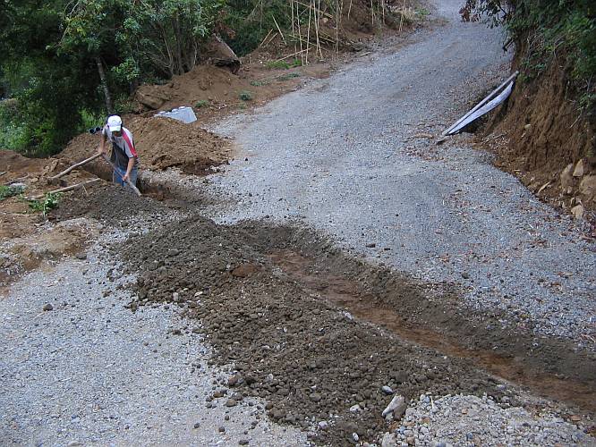
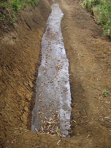
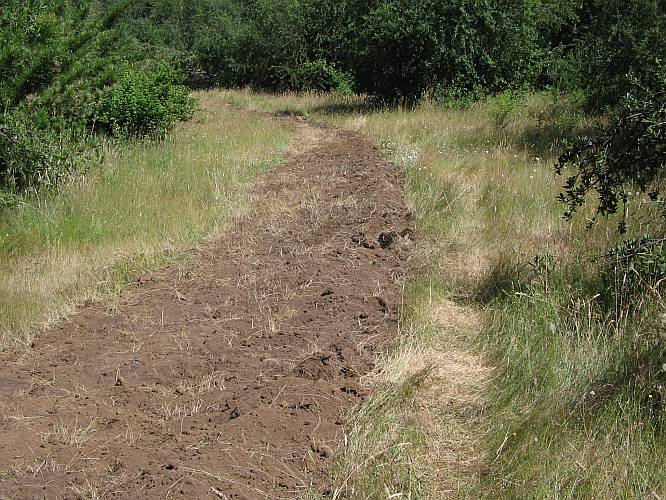
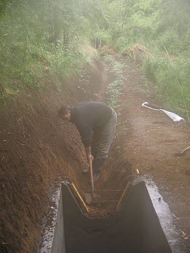
My neighbor Gabriel and his son took the hard work of digging the channel. Here you can see the beginning of the open channel that will bring the water from the stream to the forebay. A very small dam, made from wooden boards and some rocks, is foreseen to raise the water level a little bit to fill the channel.
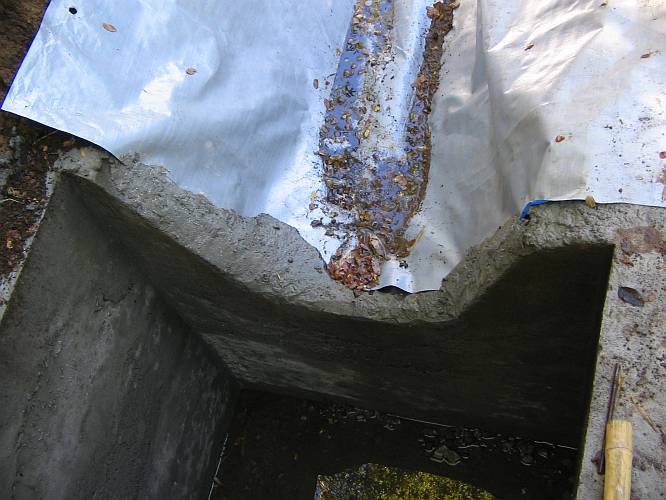
The open channel has a rounded cross section and runs with a very small slope. I don't know yet how high it will fill and thus how fast the water will flow. I also haven't decided yet whether to line the channel with concrete (good but expensive) or with polyethylene film (cheaper but not nearly as solid). In any case, some lining is required, or the water will wash away the soil. Suggestions about this are welcome.
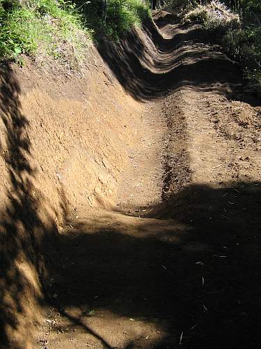
The flat area is where the forebay will be built. The intention is to square the channel there, deepen it, provide a silt basin with drain valve, then a trash filter, to end in a tank that has a water level at least 50cm above the tubing. Again, suggestions for this part are welcome.
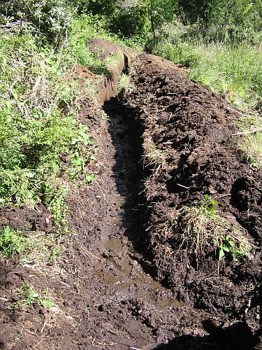
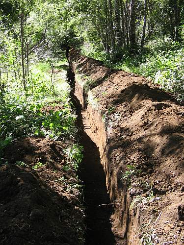
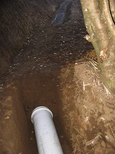
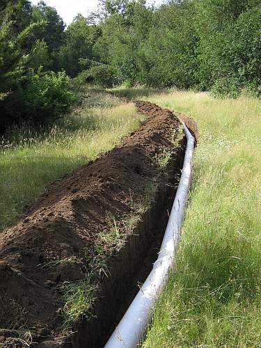
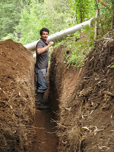
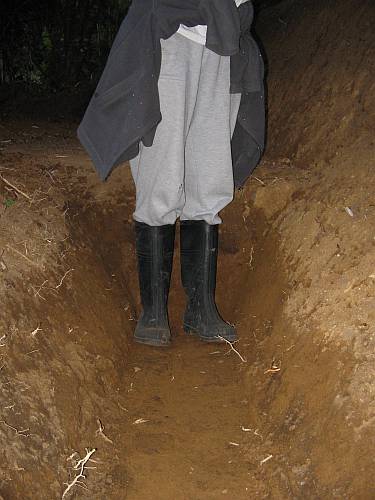
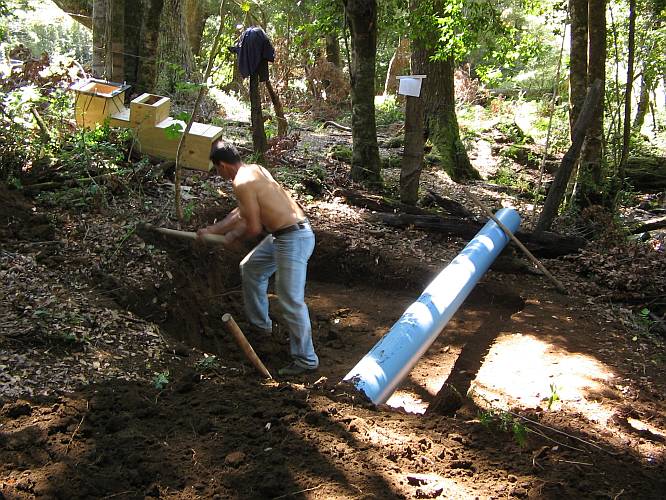
From the forebay, the 250mm PVC pipe will run underground through this trench.
The pipe will have to cross a short stretch of muddy terrain. As expected, when digging the trench through it, water seeped up. I hope to get away with simply burying the pipe in the mud, which is stabilized by grass roots. Here the pressure in the pipe is still very low (about 0.3 bar) and the run is rather straight, so it seems possible. Suggestions are welcome, in any case...
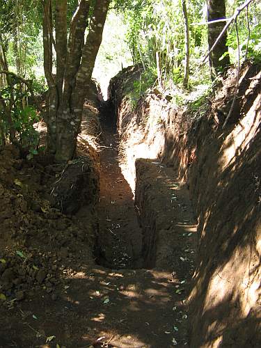
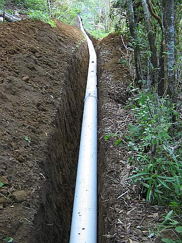
After the muddy area, the trench runs through the forest in stable soil, almost horizontally.
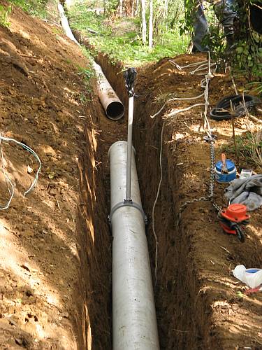
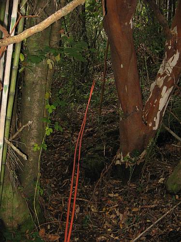
Then it reaches a place where it needs a bent downwards, to start a long downslope where we will finally start gaining some head. At this point a vent valve is planned, but I'm still a bit worried by the need to bend the pipe so much. Gabriel and his son dug very deep at this place, to soften the bend, but still it is considerable. We brought one section of pipe up, and bending it looks pretty hard. This class 2.5 piping has such thin walls that I fear melting it, burning through, or compressing and breaking the pipe, instead of bending it. Any ideas?
This is as far as we got until now. Work continues. The trench now has to cross the road, then go through a long stretch of grassland with constant slope and easy terrain, then it has to cross the stream on a wooden bridge we have to build, and then the real fun starts: Running it through forest so dense that it's hard to climb through!
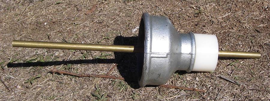
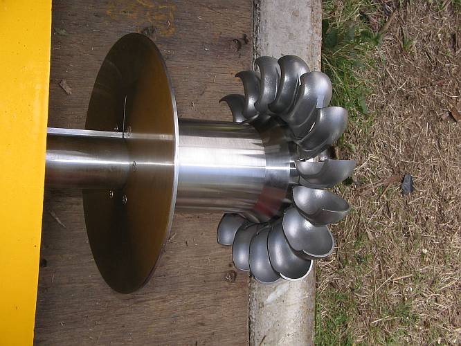
The machinery foreseen is a Chinese brushless synchronous generator with internal voltage regulator, mounted vertically on top of a pyramid casing containing a Turgo runner built from 16 spoons of the "orange" size, from www.h-hydro.com. The generator is waiting for me to pick it up, the spoons are already on hand, the rest has to be built. The turbine will use four jets. For the nozzles, I intend to use these concentric reductions:
They will be welded to flanges in the position shown here. The big side will get hose connections for 4" hose, while the small side will get homemade nozzles. The first nozzles will have 27mm outlet diameter, and I intend to turn them from nylon and give them a simple conical shape. Later I will probably make a range of nozzles of different sizes. The idea is to be able to exchange nozzles simply and quickly, by removing the whole injector unit from the turbine casing.
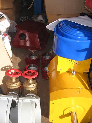
The four 4" valves and assorted fittings have been ordered but not yet arrived. I don't know yet how to make the distribution box that has to connect to 250mm PVC pipe on one side, and to four 4" brass valves on the other side, with a pressure gauge on top. Once more, suggestions are welcome!
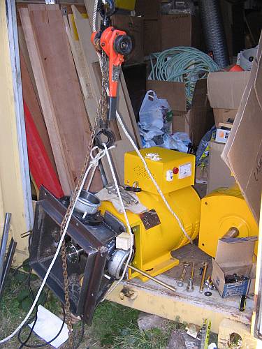
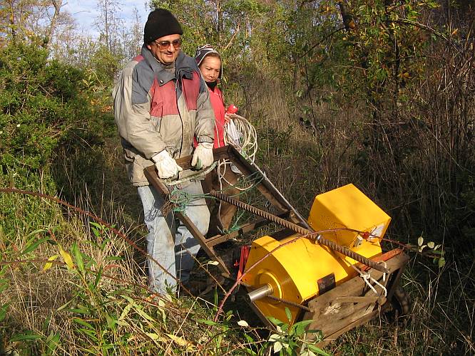
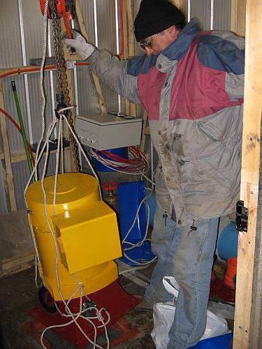
News! The generators have arrived:
These are Chinese-made brushless synchronous single-phase generators with electronic voltage regulators. The manufacturer is Mindong Wanlong Electric.Their low price made it possible to buy two of them, so there is a spare, just in case there is a failure.
Here you can see one of them hoisted into the air for unpacking. Its companion sits in the back.
At the same time, I'm finishing the detail design of the turbine. Here is a quick glimpse of a sort of schematic drawing, seen from the side, which also illustrates one of the four water jets. It's a traditional vertical axis Turgo. Comments and suggestions are welcome.
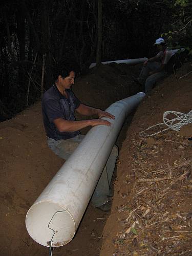
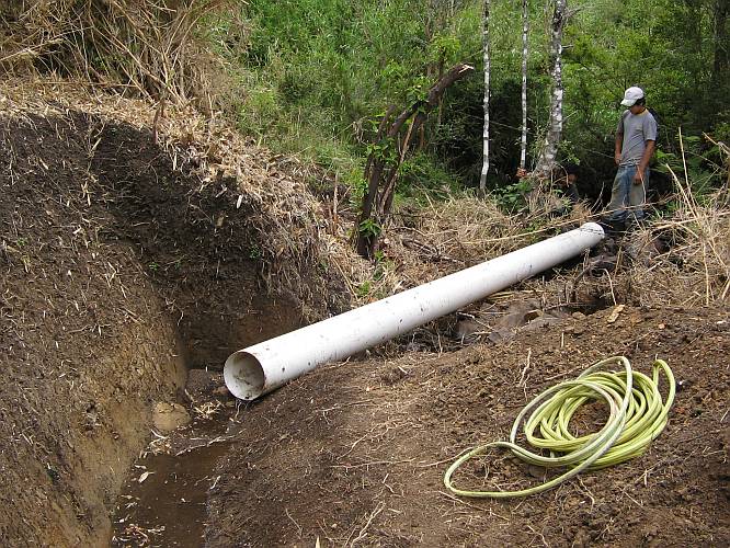
Meanwhile, work on the penstock installation continues. Gabriel provisionally put the tubes in the trench, to see how they fit. Here is the first tube, beginning right where the forebay will be. I asked him to make the trench a bit deeper here, because as shown there wouldn't be enough water over the tube.
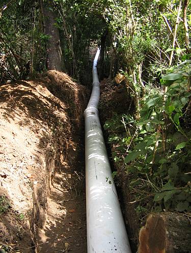
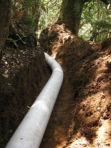
From here, the penstock runs through forest, swamp, and more forest,
and then through grassland.
From here the pipe crosses the creek and continues on the other side, through the forest, for its last 120 meters.
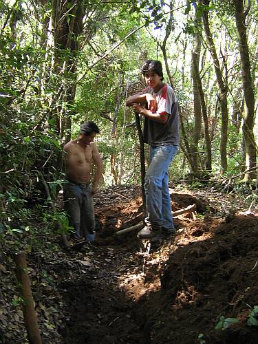
Digging a trench through the forest is hard work! It was all done by my neighbor Gabriel and his son.
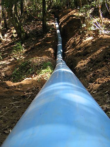
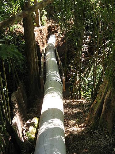
The final 24 meters of penstock drop sharply, developing 30% of the total system pressure. For this last run only, blue class 4 pipe was used. All the rest is the much cheaper white class 2.5 piping.
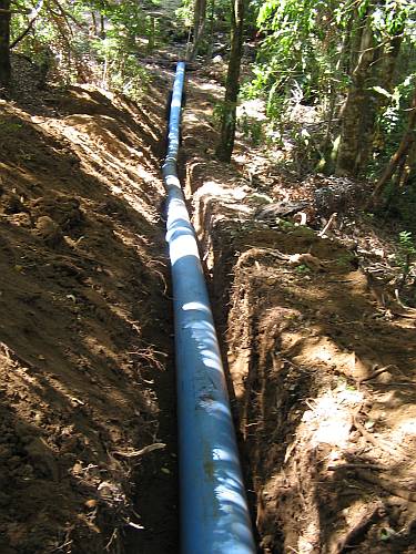
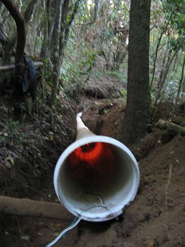
And here the penstock is seen from the turbine's perspective!
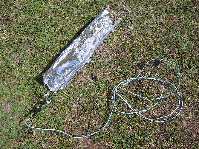
Now the final installation of the pipe can start! It has to be connected using rubber rings, and it has to be bent in many places. To bend this kind of pipe, many people use blowtorches. This is a quick method, but a dangerous one! It's easy to burn a hole into the pipe, or at least severely deform it. It's also possible to cause a fire. So I invented a PVC pipe bender. It consists of two electric quartz heating elements of 500 watts each, installed in a wire cage that slides into the tube. An aluminium foil reflector keeps 1/4 of the pipe circumference cool, to act as a stiff hinge, while the rest of the pipe will soften, in a length of about one meter.
In use, the pipe bender is fed from a portable generator. Here you can see the work at the sharpest bend my penstock requires.
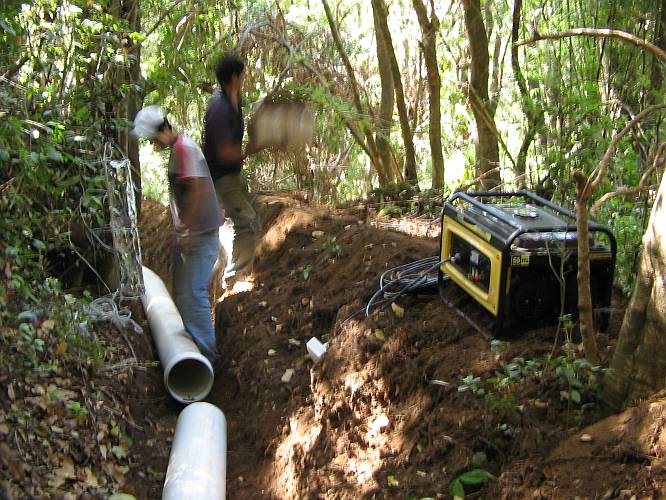
This was a typical bending setup. Gabriel acting as center point, his son as end load, and I as the controlling factor on the front of the pipe section.This piece of pipe had to be bent in three places, to give enough curving without too much weakening. We worked into the night, as you can see!
The red glow from the tube bender can be seen here. The heating is almost exclusively by infrared radiation.
And this is the result.
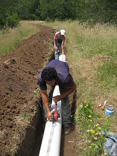
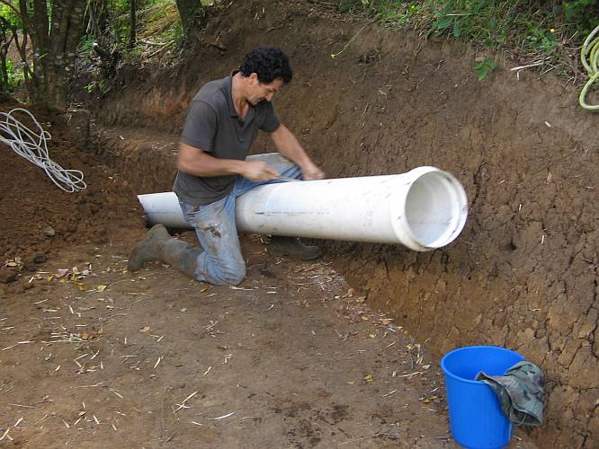
To assemble the pipes, we cleaned the ends, installed the rubber seal, marked the insertion length, chamfered the pipe end, brushed on some soap-based lubricant, plugged the the tube ends together, and then used a lever hoist and some ropes to pull it fully in.
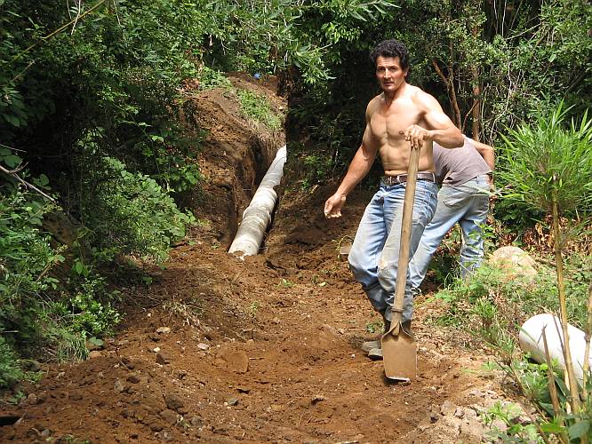
The assembled pipe is already reaching out of the forest!
And soon we were at the point where the pipe had to cross the road. My valiant helpers dug a trench through the road, we installed the pipe there, and then they closed the trench, all within two hours, so that we didn't cause an excessive interruption to the truck traffic going to the house construction site! Everything is running concurrently here!
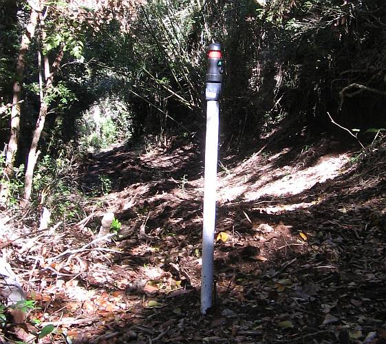
At several places we installed air relief valves. Here is such a place. A hole is cut into the tube, a collar is installed, and an extension tube is screwed in which will later carry the valve at its top.
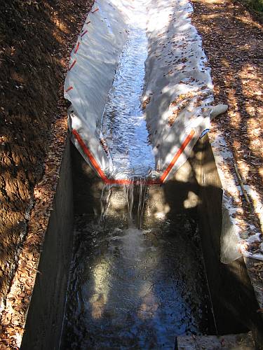
Before installing the top pieces of tube, I wanted to find out for sure if I would get enough water level over the tube, to avoid vortex formation. For this purpose, we fed some water into the channel leading to the future forebay.
The water flowed nicely along the channel, but it was clear that the slope was not constant, so I asked Gabriel to deepen both the second half of the channel, and the trench for the first two sections of tube. As you can see here, the water flows quickly down to the rock in the middle of the picture, and from there on is almost stagnant.
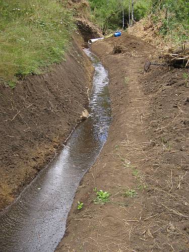
Here you can see the water pooling up where the forebay will be. Statically, there was enough water level, but when the water is flowing, the level will be lower. So we need some more depth for the tube. The soil is so dry after more than a month without rain, that it soaked up all the water we could get in! The creek was running very low, only about 10 liters per second. We fed about 2/3 of the creek into the canal, and it took three hours to fill to this level! After stopping the water supply, it dried up in 20 minutes. Clearly some lining is necessary!
And here ever-efficient Gabriel has deepened the trench for the tube!
When I bought the plastic tubes, I bought a few extra, just to be sure I had enough. I had measured the distance by GPS only, because at the time I bought the tubes, it was not yet possible to get through the jungle by the exact path the penstock had to take. As we advanced with the work, at times it looked like even this excess would not be enough! Then again it looked like only one length of tube (from a total of 84) would be left over. Finally, we finished just right, with all tubes being used, and only one and a half meters of the last piece left over! Here Gabriel is cutting off the only little piece that is left! Murphy lost the game, one time at least!
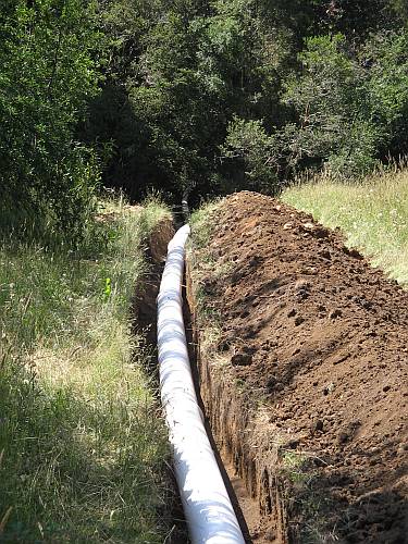
After the tubes had been installed, I asked Gabriel to quickly close the trench, to avoid pipe degradation by ultraviolet radiation from the sun, and also to let nature start fixing the damage we did. If any joint leaks enough to become a problem, I guess we will notice even so, and can dig it up again. Anyway we can't very well pressure-test the tube without covering it, because it would buckle up and become disconnected!
The soil is full of roots and seeds, so as soon as it rains again, this scar should get green and merge into the rest of the landscape.
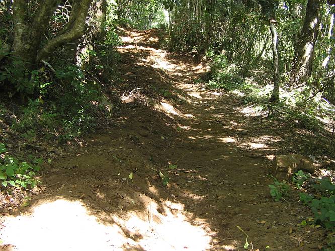
In the forest we laid the tube into a trail, which now just looks a bit more open than before.
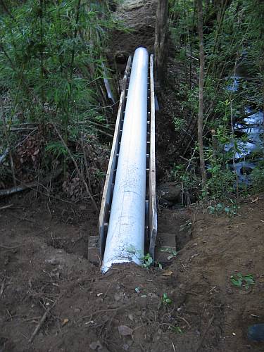
My penstock has to cross the creek. For this we had to build a bridge. I used some old timber laying around, and engaged my sister's workforce for the task.In a month's time she has to play the Baroque flute in a concert of Bach's Musical Offering, and joked that this was a great way to rehearse for the concert!
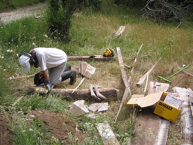
The ready-cut pieces have been carried to the construction site.
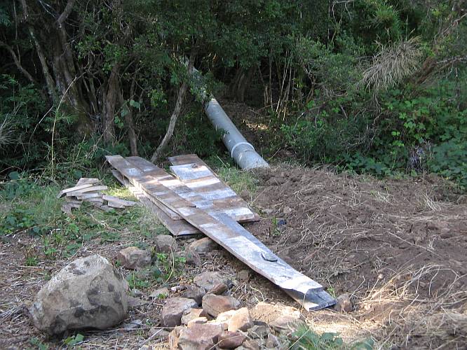
And here the bridge is in place! We installed it on four concrete blocks, to avoid having the wood in contact with the ground, which would make it rot too fast.
Later my trusty neighbor covered the tube with earth, up to the bridge ends. I will build a roof for the bridge, to protect the tube against the sun, even if here in the forest it gets rather little sun.
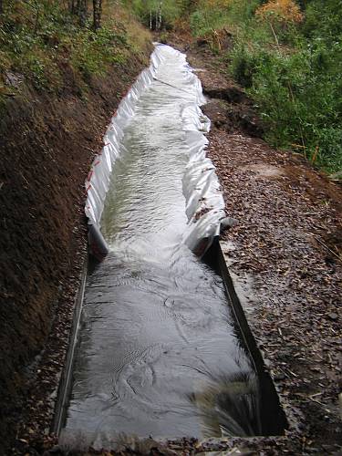
Finally the canal was deepened, to maintain enough flow speed and avoid sedimentation in it. I prefer having any sediments settle down in the forebay. My sister serves as measure of the depth of the canal.
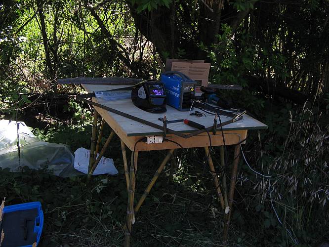
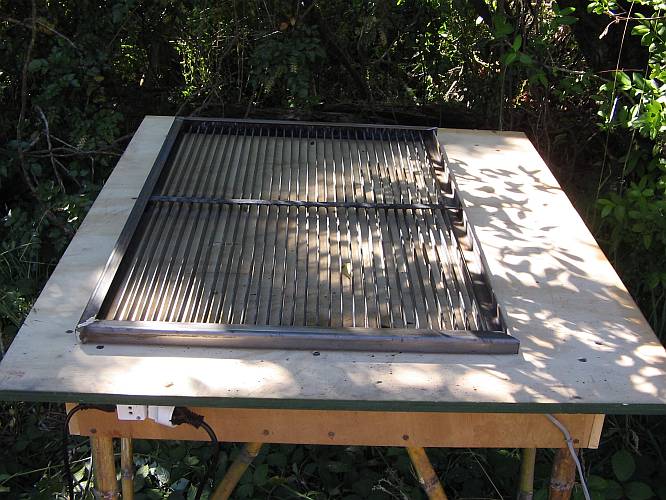
Gabriel took a well-deserved week off, and in the meantime I'm doing some steel work. Here the frame for the trash rack is about to be welded together.Note the special model table! Its top is a leftover from building the transport structure for my flying machine, two sides are leftovers from building the big box I use in the car, while the other two sides are scraps left from building my kayak. And the bamboo legs are locally grown!
The trashrack is ready! It is 1m tall by 65cm wide, and will be installed underwater in a 45 degree angle. The spacing between bars is 16mm. The mounting frame on top of it has only three sides yet, because I ran out of angle stock due to a last minute design change. This is the first thing I ever welded, so I'm glad that the resolution of the photo is too low to show all the spattering and rough finishes! The next item I have to weld is the turbine housing.
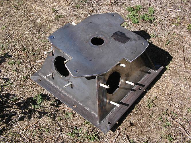
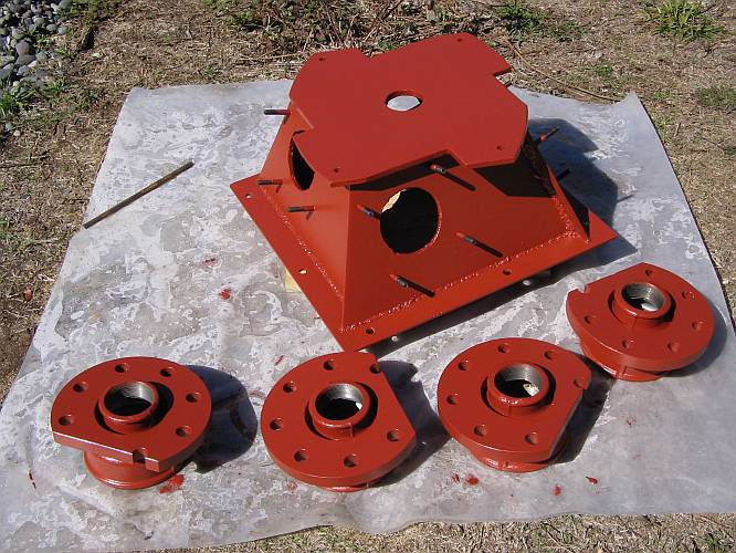
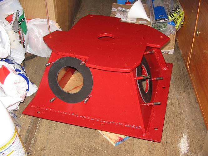
I went right to the work, and here it is, the basic part of my turbine housing, still hot from the welding!
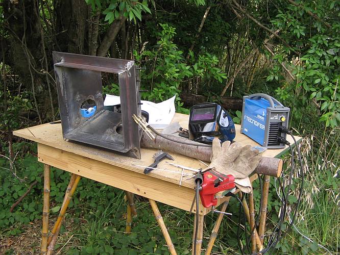
And here you can see it from the top. The welding is not perfect, because I'm powering the 5.5kVA arc welder from a 2kVA generator, which is not a very good thing to do... But I got the job done anyway!
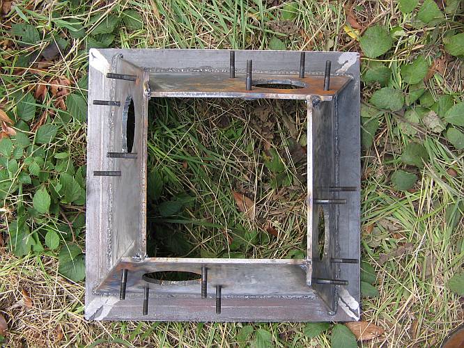
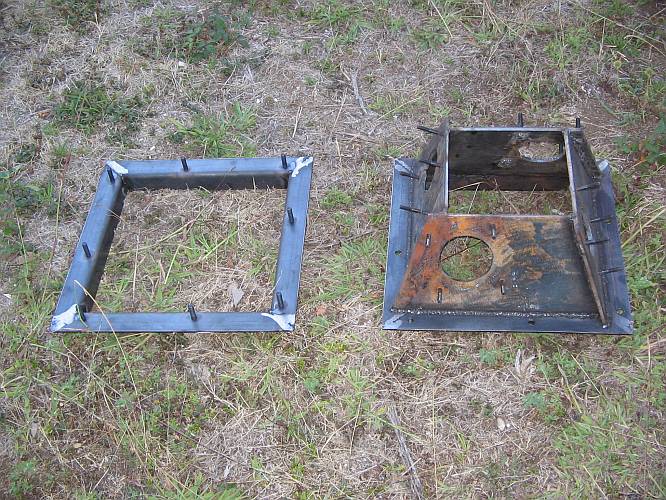
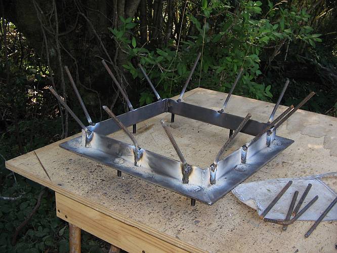
This turbine case will mount on the frame at left, which in turn will be cemented in. The bolts are welded to the structure.
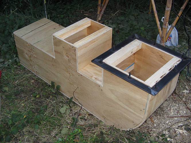
I built this wooden mold for the water outlet duct of the power house. It will have a larger opening for the turbine, and a smaller one that can be used as a general sink, or for a second, smaller "summer" turbine.
The turbine mounting frame got some spikes welded on, to anchor it in the concrete.
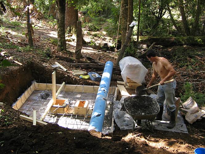
Gabriel is digging the platform for the power house.
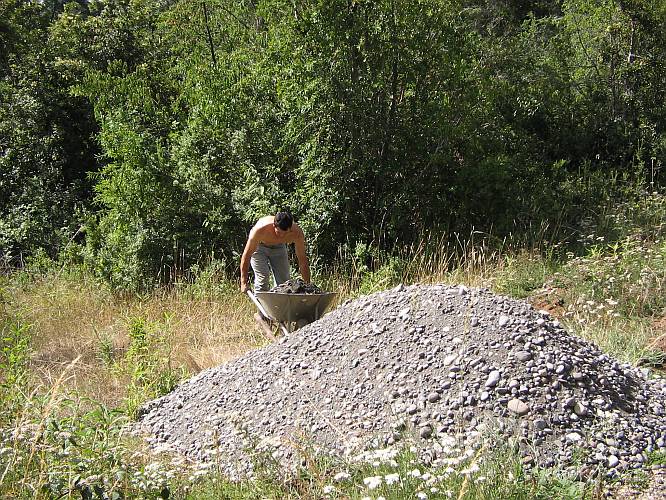
And then the hardest work started for him: Hauling in about three tons of gravel, sand and cement, by wheelbarrow!
All this material had to be mixed by hand. While he mixed and poured concrete, I finished the steel structure. In this photo the outlet channel is already made. Note that this channel also acts as main anchor for the pushing force exerted by the water in the penstock. In addition, there are two smaller anchors in the corners of the concrete slab.
While Gabriel continued making and pouring concrete, I cut the penstock to length, installed a cap, and installed steel and mould for the tube anchors.
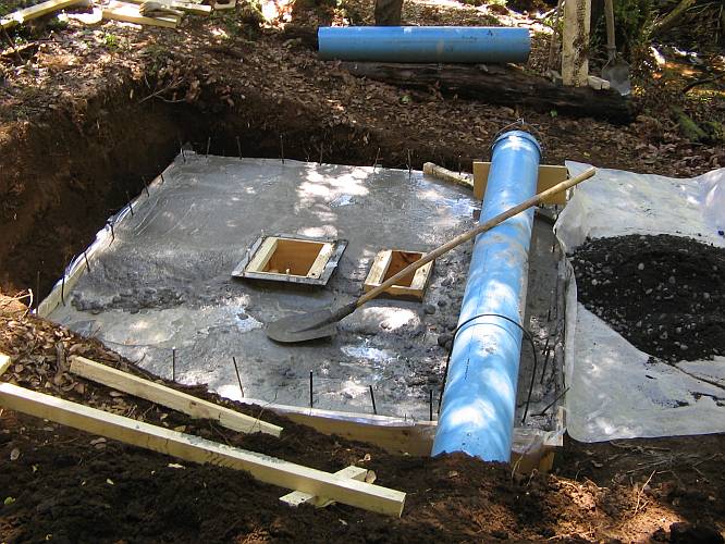
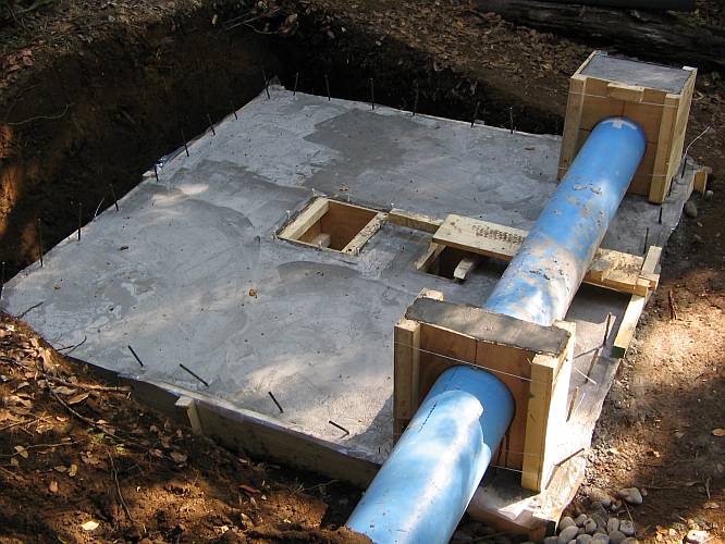
The concrete work is ready!
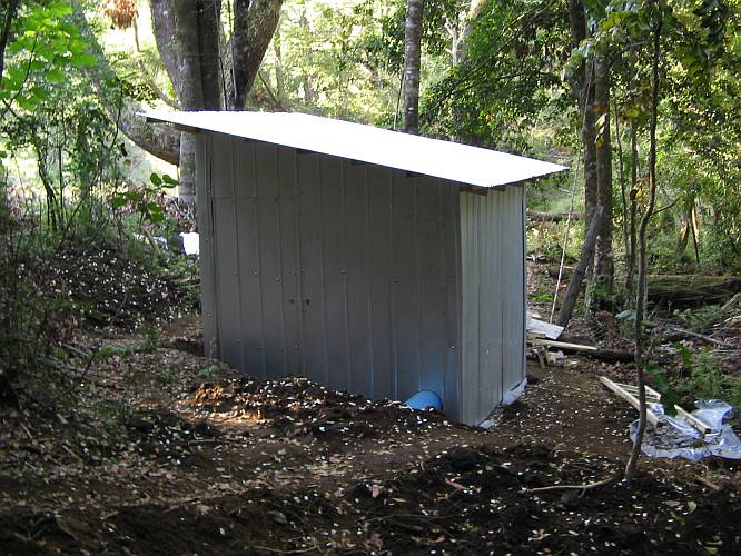
After the concrete had set, I built the power house on it. Here you can see the finished structure. All wooden pieces were cut to size at my little cabin, then hauled to the site and assembled there. Incredibly enough, they actually fit! :-)
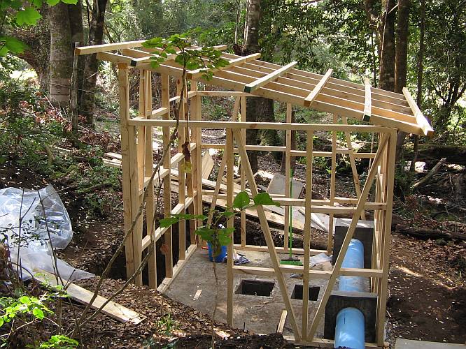
Metal sheeting was used for both the roof and the walls. I will probably paint it later, when there is more time. Also the wall sheeting still needs a few more nails. This is the first house I ever built with my own hands, so watch it with due respect!
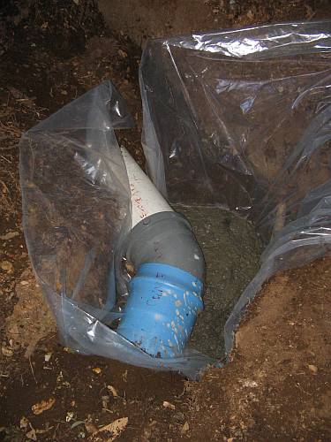
You might remember that my penstock has a 135 degree elbow. We cast concrete around it, to make a nice anchor block. We filled in concrete to about 10cm above the plastic.
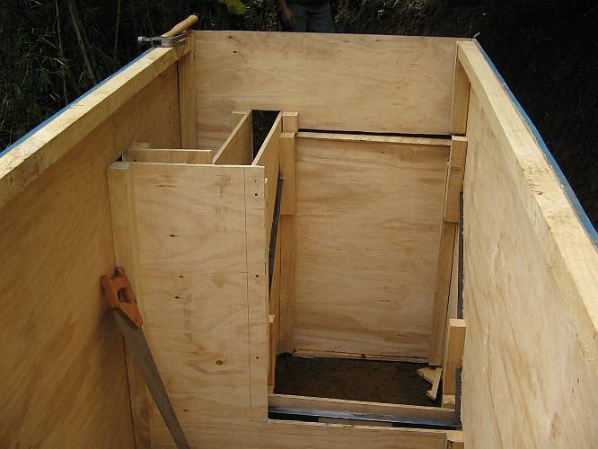
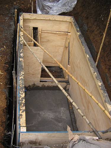
The power house being ready, work at the other end of the system needed to be done: The forebay. Here is the mold and steel structure for it, with the frame for the trash rack already installed.
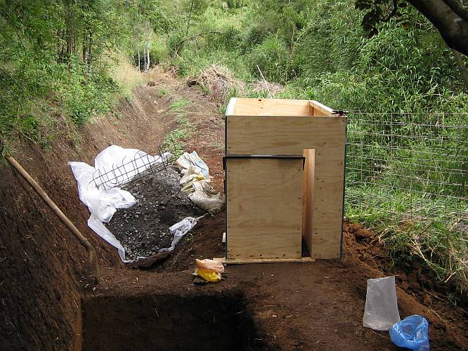
The mold looks quite complicate. This corner has the overflow chamber.
We lowered the whole thing, steel and all, into the hole dug by Gabriel. We got caught under the behemoth (2.44 * 100 * 122 cm) and had some trouble getting free again! Then we poured the concrete for the floor.
When the floor had hardened enough, we slowly filled the walls.

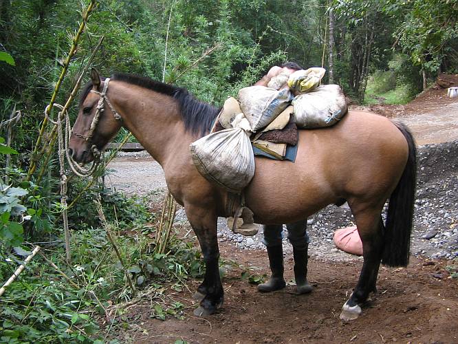
My largest fear was how to haul all the gravel, sand and cement in. Here we needed slightly more material than for the power house, and the trail to this place is steep uphill. Not even Gabriel could push a wheelbarrow full of stones up this trail! Ever resourceful, he went to his land (neighboring mine) and came back with the perfect tool for this task: His horse, and some sacks.
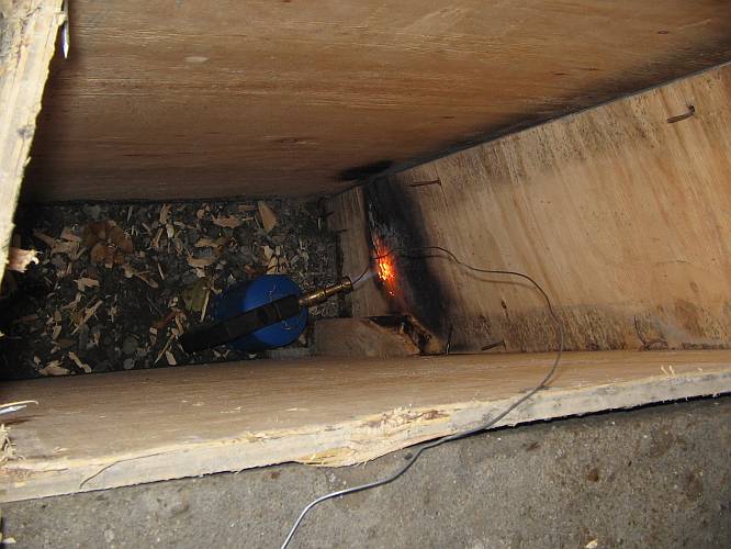
After allowing the concrete to harden for a week, the molds were removed. This was really difficult! The molds inside the overflow chamber had to be burned through with a blowtorch, not easy at all with wood totally soaked by the wet concrete and the rain!
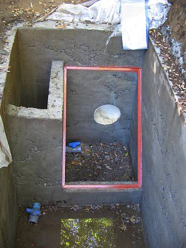
Unfortunately, what emerged under the wood looked really terrible. Despite all our attempts to properly compact the concrete, things went wrong and the concrete looks roughly like a Swiss cheese. At many places the little sand in our mixture had failed to get past the many stones, leaving lots of air spaces. You might not believe how hard it is to get sand here! The material I got for the forebay was a natural mix of sand with stones of assorted sizes, but clearly it had too many stones and not enough sand. To avoid further delaying matters, I decided to try using the forebay like it is, rather than trying to line it with another layer of concrete, or demolish and rebuild it, which would be the only really good thing to do. At least, the steel frame that will hold the trash rack got a nice coating of anticorrosive paint...
In the powerhouse, the mounting frame for the turbine also got anticorrosive paint.
You might imagine that anyone visiting me here has to work! When the Capt'n of the Capricornio came for three days (look in the Nauticus section of this web site for stories about my trips with him aboard his sailboat!), it was time to finish the feed channel. Here you can see him doing grueling shovel work, in the midst of autumn fog.
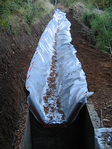
I lined the channel with plastic cloth, and tried to connect it to the forebay with some concrete. But the night after I tried this, it rained unexpectedly. Water got under the cloth, lifted it up, washed away much of the uncured concrete, and destroyed my work.
To prevent this from happening again, I then connected the cloth to the forebay using a steel frame installed with screws. It's not 100% watertight, but with some luck it might be good enough. At this time, winter is coming, the creek is rising, and I want to get my system running as soon as possible!
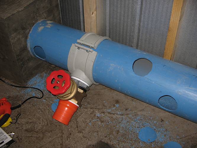
Now I have to install the technical equipment. This is a tube collar with valve and hose barb, of which I will have four in the power house.
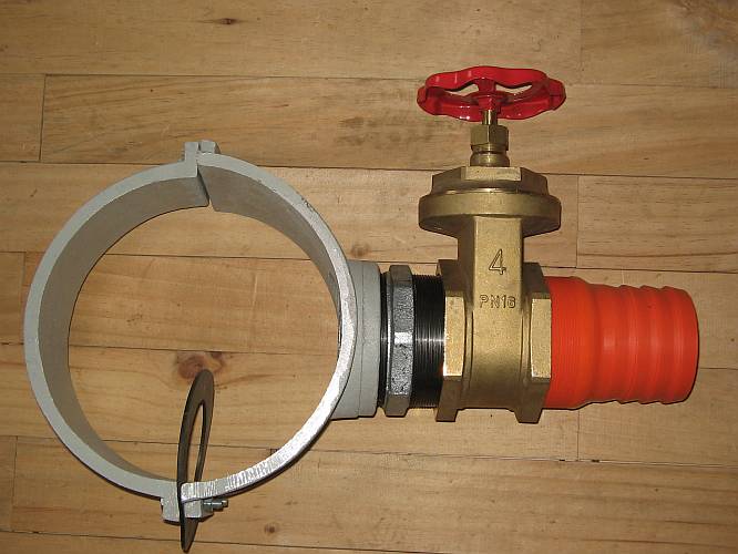
Unfortunately the collars and nipples are of horrible quality. The collars are cast aluminium, terribly porous, almost as bad as the concrete of my forebay... The threads seem to be made in casting. And the nipples are zinc dipped cast iron. This material is brittle, and many chunks of the threads are simply missing. On top of that, the threads of the nipples are far smaller than the specs require, so they screw fully into the collars before their tapers even start to adjust. The valves have better threads, but very much shorter than the minimum required by the specs of the BPST thread. They fit the nipples so loosely that they almost fall off! I tried to wind on an almost grotesque amount of teflon tape, and assembled the stuff, but I fully expect these assemblies to leak everywhere. If the leaks are not too bad, I just will build dams and canals in my powerhouse to channelize the leak water away... but if they spray all over the place, I will have to find another solution. Suggestions are welcome.
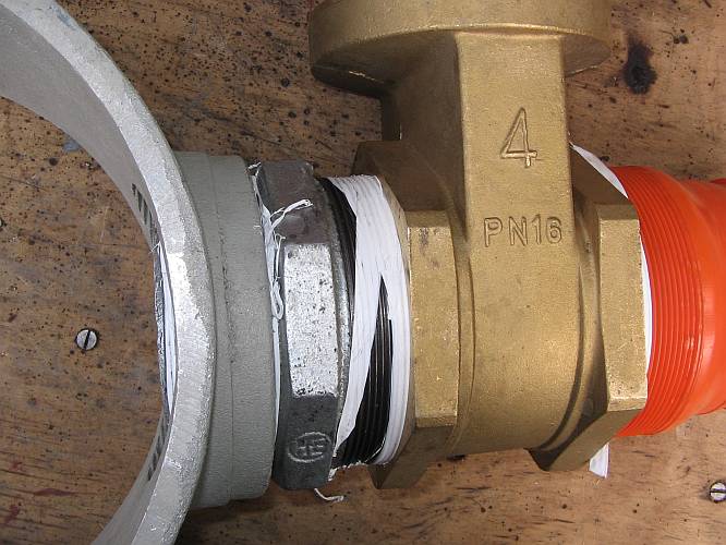
Here you can see a detail of how the nipple protrudes deep into the collar, where later the plastic penstock will be. I solved this problem by grinding off the protruding parts, after taking this picture.
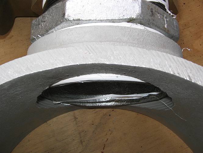
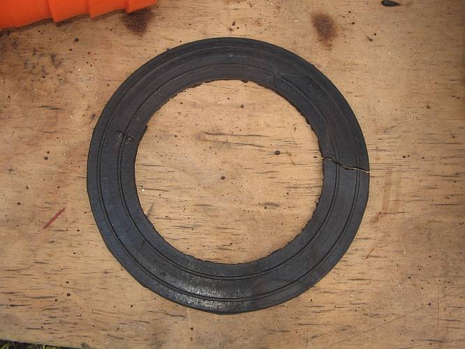
The collars come with their rubber seals. Oh well. Two were usable. Another looked like this, with a big break. And the forth simply was missing. I had to make replacements for those two, but I can't make them with the two ridges, which might be necessary to seal against the very rough cast aluminium. It's really a disgrace to have to deal with such low quality products, but unfortunately these are the only I could get.
While fair weather days were used to do the outside work, on rainy days I did indoor work like machining the nozzles. Once again, my hobby lathe is providing good service! I can even make the tapered threads on it!
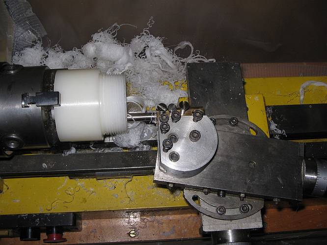
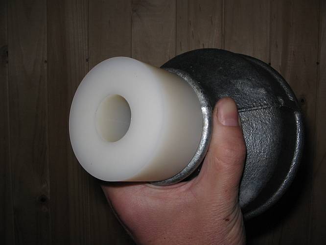
Here is one finished nozzle, mounted on a reducer. It's conical inside, while the outside is a simple cylinder to allow easy gripping in the lathe. It's made from a polyamide 6. The exact brand name of the material is Ertalon 6SA.
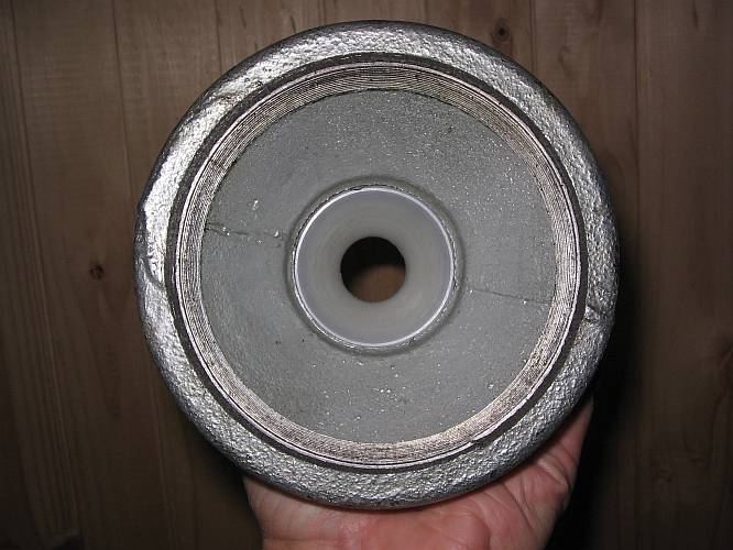
Looking through the reducer and nozzle! The perspective is a bit misleading in this closeup photo. In truth, the hole is about one quarter the diameter of the thread.
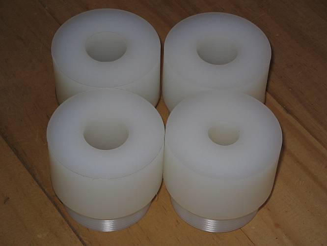
And here you can admire all four nozzles, to be used initially. Three of them have the nominal 27mm bore, for 12 liters per second. The fourth is a "half nozzle", with a 19mm bore that will give a flow of 6 liters per second.
The turbine case was completed next. The top plate got some cutouts to allow easier mounting of the injector assemblies, and was welded on top of the side walls in a somewhat twisted position. While unorthodox, this position allows the easiest access to all screws. Nobody has ever cast in stone that all things have to be perpendicular to each other!
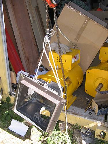
Test fitting the turbine case to the generator. The case can be lifted by a single person, but to bring it close to the generator without bumping it, and then installing the bolts, I preferred to use my hoist. Anyway I needed the hoist to move the generator to the edge of the container door, because that one cannot be lifted by one person!
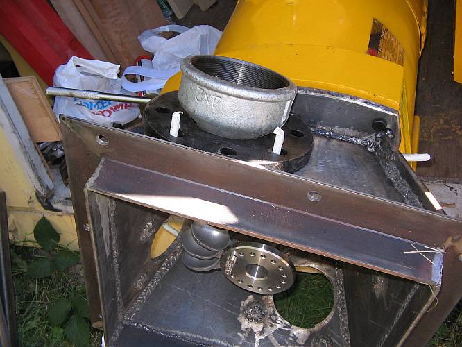
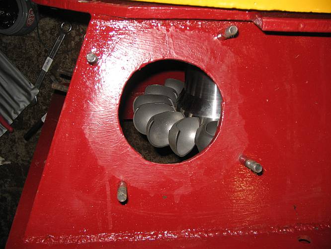
The task on hand now was welding the concentric reducers to their mounting flanges. The flanges allow fine tuning of the position of the complete assembly, but the coarse alignment has to be done by rolling the reducers in the flanges, before welding them. For this purpose, I installed a few turbine spoons, with the rear piece of the runner, so I could aim the reducers and tack weld them.
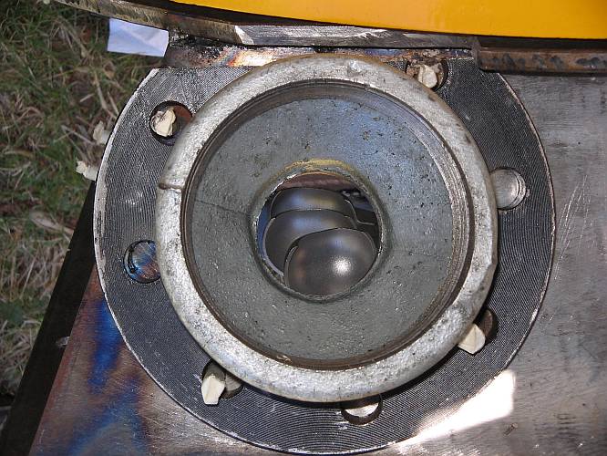
Very coarse aiming can be done visually, but this is of course not precise enough! For a photo it's nice, though!
I made a simple injector alignment tool. It's an unfinished nozzle that has a straight bore of 12mm diameter, into which a 12mm brass rod fits snugly. The rod can be pistoned in the pseudonozzle.
Using this tool, it's easy to see exactly where the water jet will land. The only problem was to decide where exactly on the spoons the jet should land! Good information is hard to come by. I finally made the center line of the jet hit the spoons about 8mm below the top surface, at the point where the spoon center line is perpendicular to the jet. Also, I placed the jets on a slightly smaller radius than the center of the spoons are, because this will keep the outer parts of my rather thick jets from missing the spoons. In any case, the position of the jets can be fine tuned later about 8mm to any side.
You can see that holding things together for tack welding is not so very easy! A helper would have been welcome, but I had none.
And one more photo, where you can see one nozzles and the alignment tool in place. Tack welding the underside nozzle was particularly funny, lying on my back in a forest ants nest in front of the container, and welding overhead at short distance!

After tacking was complete, I fully welded the injector assemblies, and then these assemblies and the casing finally got a much deserved coat of anticorrosive paint, which was then hidden under mandarin red paint, a tribute to the Chinese generator this turbine will move!
The finished turbine case, complete with rubber seals, ready for installation!
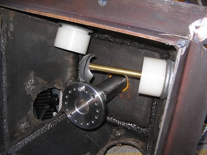
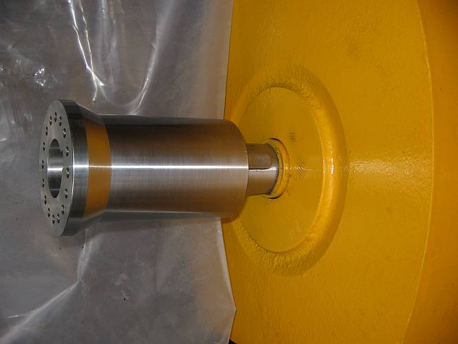
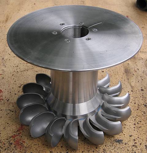
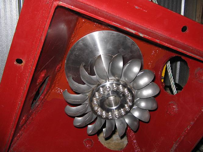
The machined pieces for the turbine runner are the best made parts of the whole system. They were made from stainless steel in Oscar Quijon's workshop in Santiago, to my design. Here you can see the main piece, mounted on the generator axle.
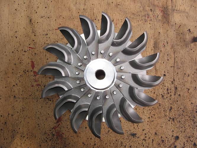
The complete runner was test-assembled, to check the fit of the spoons, which have to be machined a little to be used on a 16-spoon runner.
This shows how the spoons sit on the runner back piece.
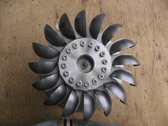
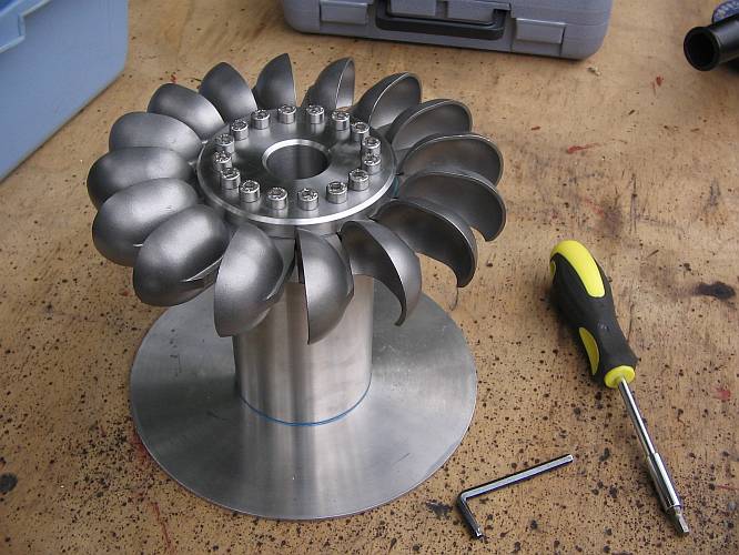
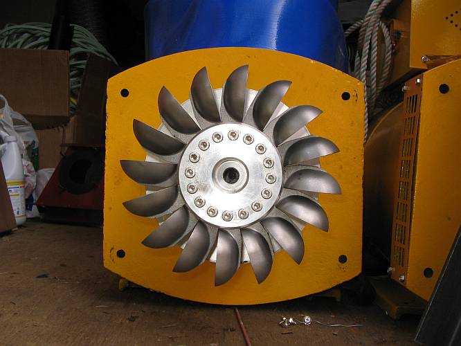
When I was satisfied with the fit, I assembled the runner, complete with water thrower disc, and with Loctite thread sealant in all threads and mating surfaces.The ugly scratch on top of the water thrower plate was my fault, when my Dremel tool slipped while making the key cutout in the disc, which was not foreseen originally and thus not made by the workshop. The scratch is very shallow, in any case.
And here the same thing from below. I torqued the bolts to the optimal force calculated by my friend Michael, who is an expert in the matter.
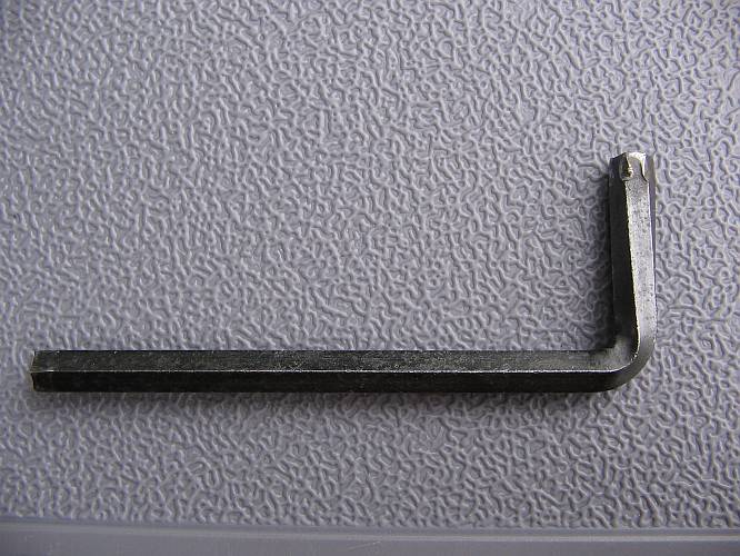
The only problem was that the Chinese-made Allen wrench wasn't quite up to this torque!
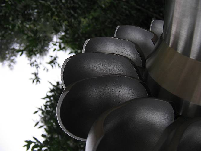
Allow me some artistic expression in this series... such as Hydromechanics and nature!
Finally, the runner was stored on the tip of the generator axle, waiting for action!
Looking from "below". Once assembled, a bolt with large washer will hold the runner to the axle. This same hole is threaded with a larger thread (which was funnily forgotten by the machinist in Santiago, and had to be made in Temuco later!). Using this thread, a long bolt can be inserted and used as extractor when the runner has to be taken off the generator for bearing maintenance.
My storage container is starting to look interesting!
Final installation has started! Here you can see all the plumbing, in my car, on its trip to the powerhouse.
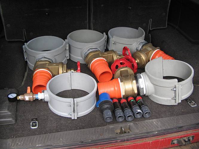
Hey, after cutting all these holes, I could now start a flute factory!
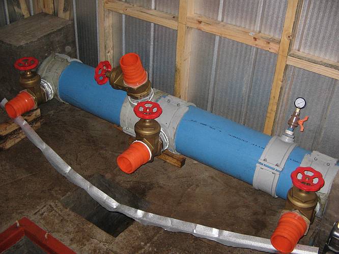
The four valves and the manometer have been installed. The next step is feeding water into the penstock, and watching where it will burst or leak! There is no question that it will leak - the only questions are how much, and at how many places!
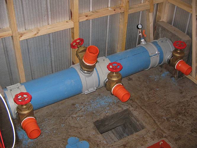
I also installed the air release valves along the buried penstock.
The high voltage line from the powerhouse to my little cabin was also built. First, I made two dozen of these assemblies, which would be used for joining the conduit sections.
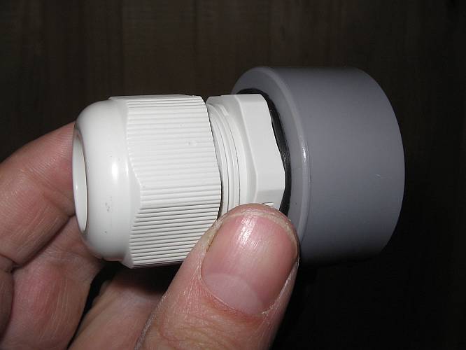
The line consists of two 16mm conduits, each carrying a single 1.5mm2 wire, of the common household type that has a PVC insulation rated for 600V. I will run this line at 2kV between wires, with a center connection at ground potential, so that each wire sees only 1kV over its insulation plus the conduit. That should be safe even if water gets into the conduits! The line was provisionally laid over the forest floor, but will be buried for safety by Gabriel. Anyway I will use it at 220V only, with low power, until the transformers are ready.
Here is a splice point. The conduits and wires come in 100 meter lengths. I soldered the wire ends together, insulated them with Scotch Super 33+ tape (the only insulating tape I can really recommend!), and then slid my joining pieces over the ends of the conduit, and torqued them shut. These joints should be pretty well sealed.

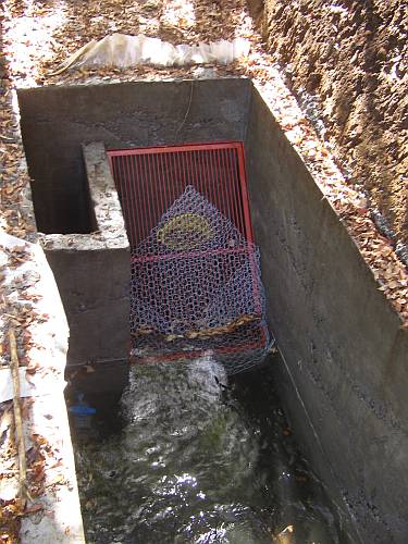
The next step was testing the penstock and plumbing. For this purpose, I needed some water in my forebay. The work started by cleaning away some of the dead brush that was completely covering the creek at the place where the weir needs to be built.
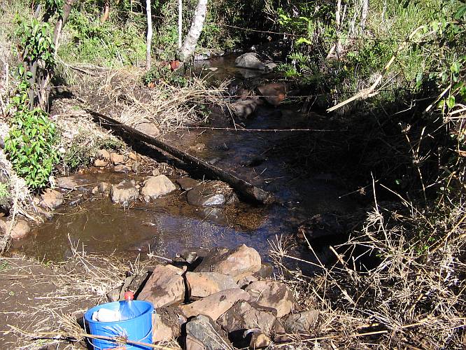
A simple wooden weir lined with plastic cloth soon had a trickle of water flowing into my forebay, not enough to run the turbine, but enough to slowly fill the penstock.
To keep the dirt out as much as possible, I provisionally installed a spaghetti sieve in the penstock inlet!
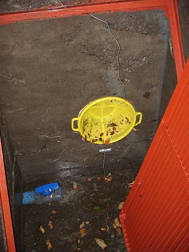
A piece of chicken wire over the main filter also helps, and the penstock is filling!
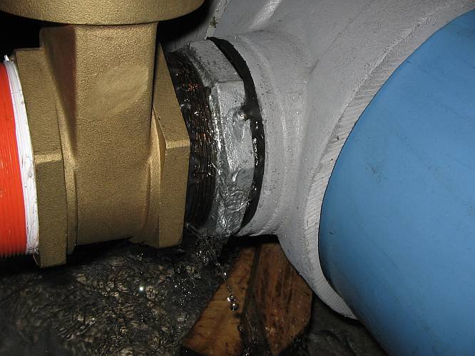
In the power house, meanwhile several new springs were showing up. The rubber rings that came with these collars were hopelessly useless. No amount of tightening the collar bolts would make them seal, because the pipe deformed under them.
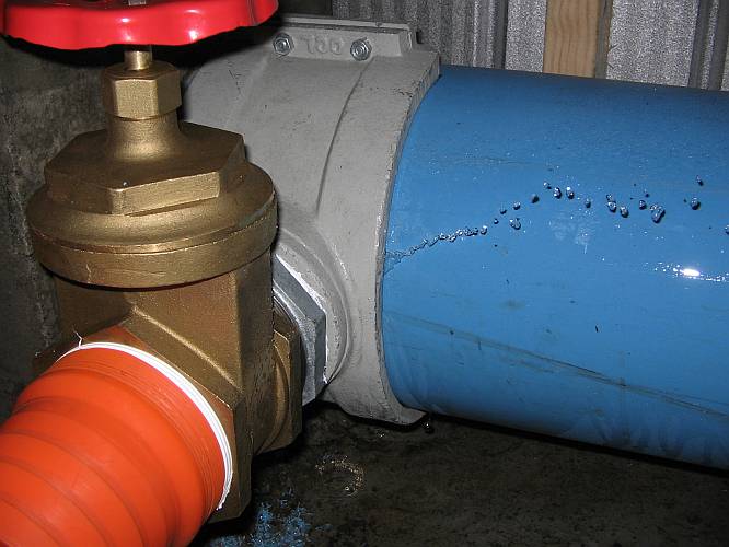
And the teflon tape in the threaded joints didn't do a better job. These threads are unfortunately of such low quality, that the teflon tape simply cannot seal them.
Water was dripping everywhere! And this was with the penstock just starting to fill, with a pressure that was only 1/4 of the final working pressure!
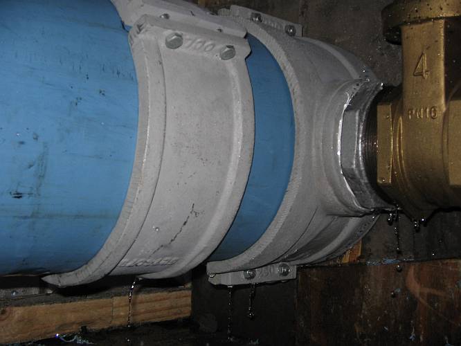
So, I disassembled everything again, cleaned out the teflon residues, and reassembled the threads using a tixotropic anaerobic thread compound. According to its label, it would harden in 12 hours. I let it harden for two days. But it didn't harden at all, not even the slightest bit! When I did the next water test, the situation was much worse than with teflon tape! Now, absolutely every thread leaked!
I had also replaced the original hard rubber rings that came with the collars by much softer ones, hoping they would better seal the collars to the penstock. Some actually worked, but others did not. The pipe was already too deformed from the pressure of the hard rubber rings.
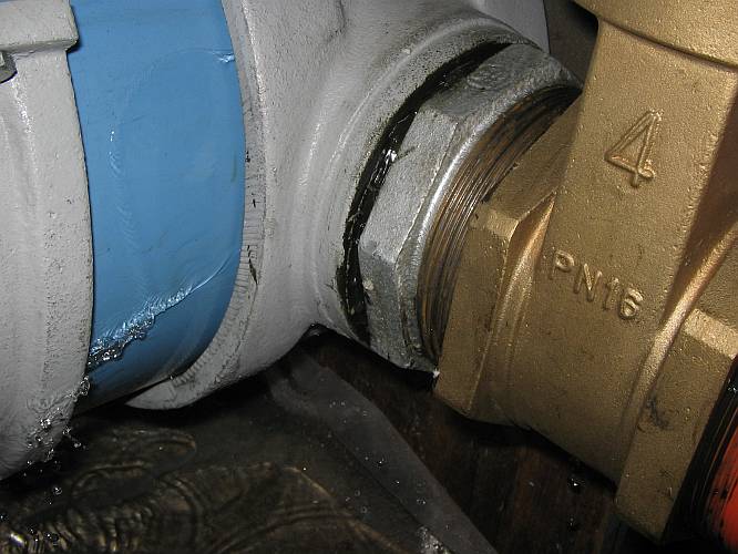
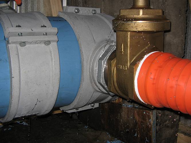
The situation was really between funny and ridiculous. Note the manometer. I have 0.1 bar in the penstock, and still all joints are dripping!
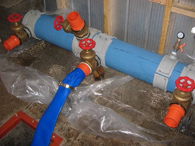
The solution to this problem was silicone caulk. I again disassembled everything, cleaned the black useless sealant away, discarded the rubber rings, and reassembled everything using silicone caulk. Now everything is watertight, at the full working pressure! There was only one tefloned joint left, at the center hose barb. I left it just to see if this joint of rather well finished plastic with brass would hold water. When I connected the hose and tried it, I found that it leaked too, so I had to seal it with silicone too! Lesson learned: Teflon tape is useless for big threads, and gasfitter thread goo is even more useless. On the small threads of the manometer connection instead the teflon tape works well.
The metal water canal in the photo is there to take care of some water dripping through the valves. The factory new metal to metal seals need to set in first, before sealing hermetically. But that's not a problem.
And then the rain came, putting a sudden and violent end to the long lasting drought. It rained 400mm in a few days, and while I write this, it's still raining, with only one day of of break in between. My little almost dry creek quickly swelled into a big torrent. Its bed clogged with dead plants, almost the full creek went into my canal and forebay, resulting in damage to the canal.
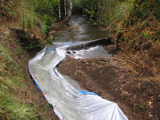
I tried opening the weir, but couldn't. Everything I tried just worsened the situation, so I'm now pretty helpless and watching how nature has its way. Specially bad is that a lot of water is going under the lining, causing much damage.
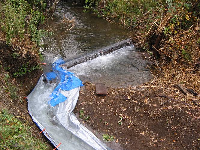
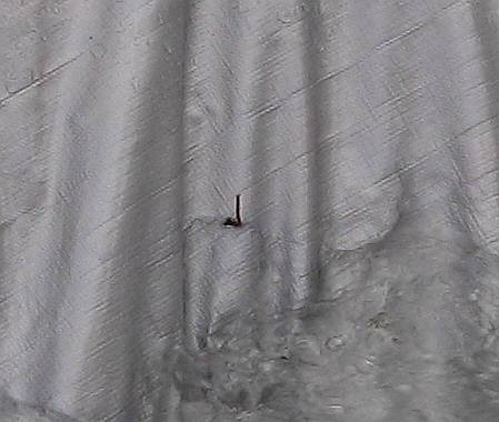
The cloth is moving constantly between the two layers of moving water, and this motion makes it chafe against rocks, roots, twigs, etc, and all such places are becoming damaged. Here you can see a tiny twig that worked its way through the canal lining. So, the lining, a 200 dollar investment, has essentially been lost, even before the turbine has been installed!
The canal overflowed and eroded the soil at three places. But at the same time I'm getting about 180 liters per second of water into my forebay, more than three times as much as my turbine can swallow! Happily, the spill gate of the forebay works well, and there has been no damage so far.
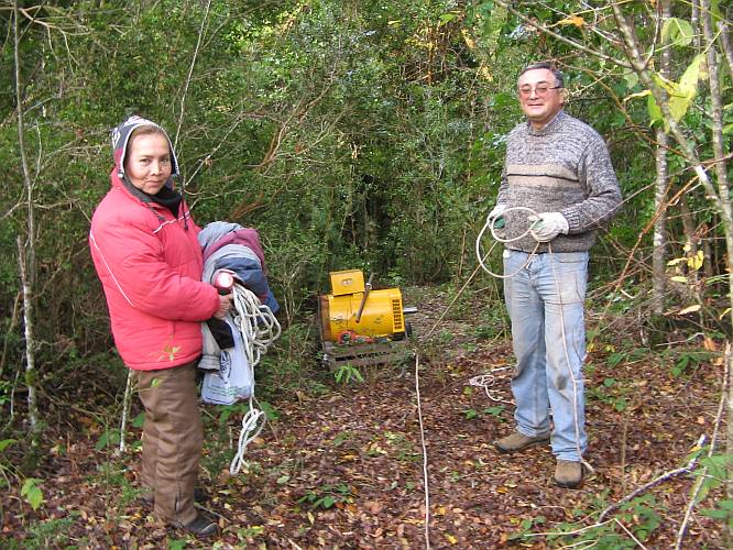
Having enough water, it was time to start up the system! After a solid week of continuous rain, there was one single fair weather day. My friends Manuel and Ariela came over to help me with the hard job of hauling the generator to the machine house. We used a two-wheeled cart for the task.
At the steep places we tied ropes to trees and used mountaineer's methods to slowly let the generator with its cart down the slope.
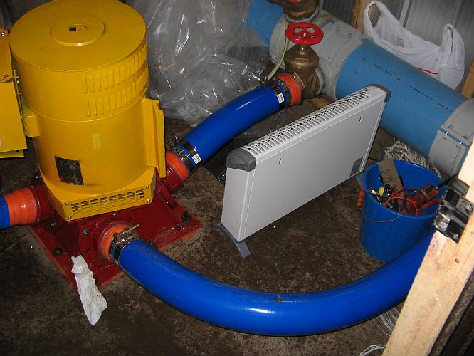
And here it is, in the machine room, dangling from the hoist, with the turbine already attached!
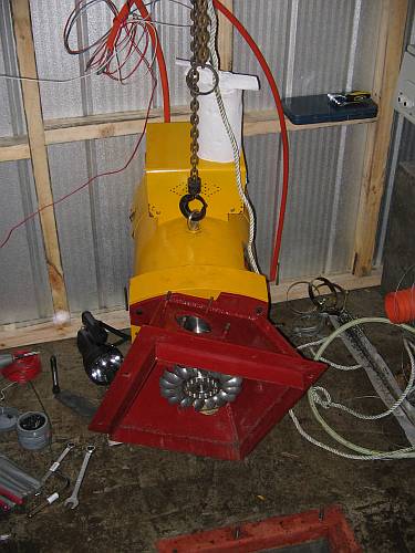
A last look at the turbine, before installing the machine on the outlet channel.
Then the machine was tilted into the vertical position and lowered onto its pad.
A last look through one of the nozzle mounting holes, before installing the nozzles for good.
With the nozzles installed, and two of them connected, I opened the water valves. But I got no voltage, and the generator ran very slowly. A moment later, it started smelling of hot plastic, and another moment later, smoke came out of the generator's AVR box!
It turns out that at the factory the box was miswired, so that the AVR was disabled, and a dead short placed across the output. This shorting wire was a thin one, and this was the one that smoked, when the generator put who knows how many amperes through it! Here you can see the miswired box. Note the two power leads of the AVR, coming from THE SAME post of the voltmeter! And then follow the thin wires between the left output post and the circuit breaker, and you will see the short circuit.
I don't know if this miswiring is done on purpose, for safety reasons. But if so, they should mention it in the manual!
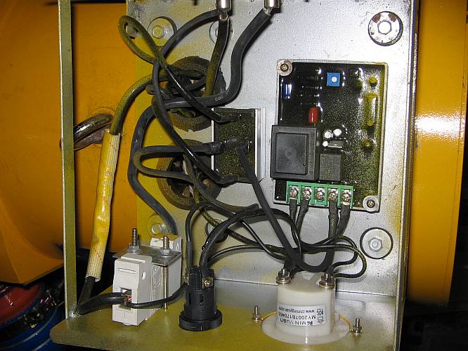
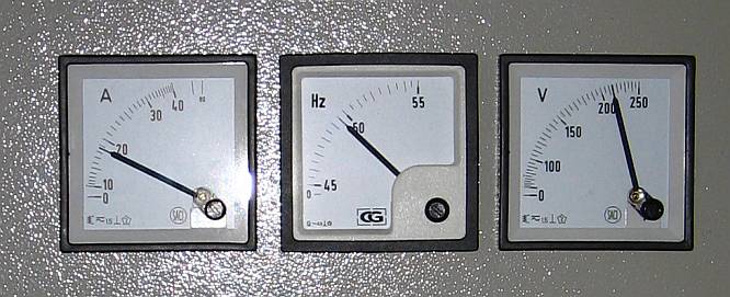
After flipping the two wires, everything started running! I adjusted the voltage to 230V. The frequency is held to 50Hz +/-1Hz by the ELC. I had preadjusted it in the lab, before moving, and no further adjustment to the ELC was needed.
I did some load step tests, and everything seems fine. Each full size nozzle seems to be producing a tad over 2kW, while the small size nozzle produces about 1kW. The generator needs several hundred watts for its base loss (excitation, friction, ventilation). With one large and the small nozzle active, I had about 2.3kW of output power. This promises close to 8kW when using four large nozzles, and this would be on the upper side of my expected range! That's good news. Pressure drop in the penstock was very small with these two nozzles in use, so it seems that the math was correct in this regard too.
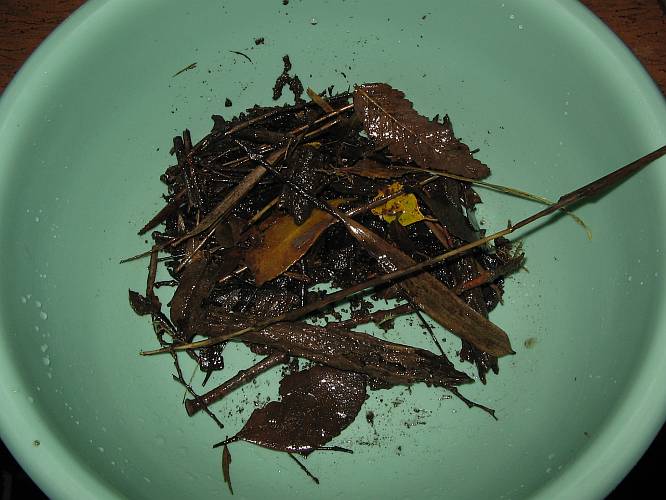
So I closed the machine room and went home to enjoy my hydroelectricity. But it didn't last long! The lights went out even before I arrived. An impressive amount of organic debris had clogged the intake screen. Here is a small sample of it: Some leaves, lots of twigs, and many larger pieces of rotten wood. I have a fine wire mesh screen in place that holds all this back, but that can't work without clogging. Leaving just the coarse screen of parallel bars, much of this debris would get through, so it would clog slower, but then I fear that my nozzles will clog faster than the screen! And they are harder to clean.
Fortunately the problem for the most part solved itself. This huge amount of debris came in because of a combination of the flooding rain after long drought, and running the system for the first time, which flushed all loose debris in the channel. After cleaning everything, the self-cleaning of the filter is now operating perfectly. There is enough flow into the loading chamber to cause some turbulence, which keeps even the fine meshed filter clean. Often a twig or leaf settles momentarily on the filter, only to be dislodged and flushed over the spill gate seconds later. As I write this, the turbine has been running for exactly three weeks without any manual cleaning required.
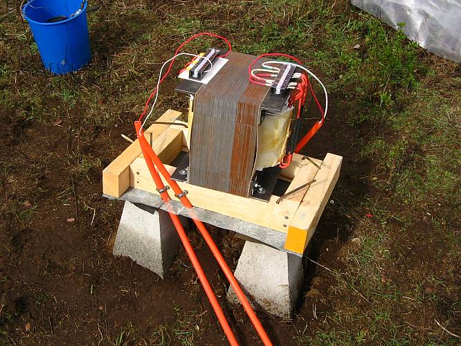
With the turbine running smoothly, it was time to make the transformers, to be able to transport the full power to the house. The 600 meter long line was designed to have low loss when operating at 2000 volts. At 230V, the losses are extremely high at anything over a few hundred watts. So, here I go...
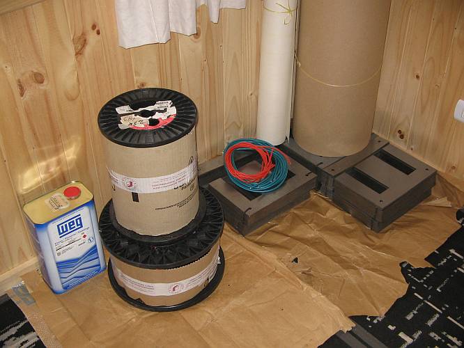
Here is the material. You can see the nice stacks of silicon steel E-I laminations, two coils of enameled copper wire, two rolls of insulating material, a can of impregnating varnish, and some spaghettis. Not shown in the picture are some bolts, steel angle stock, the terminal strips, and cotton straps.
The E-I laminations measure 30x25cm, and the full stack (for the two transformers) is a bit more than 30cm high. Don't let these low numbers fool you: The steel weighs no less than 140kg! And there are 55kg of copper wire, but not all of the wire was used. Only about 80%.
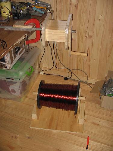
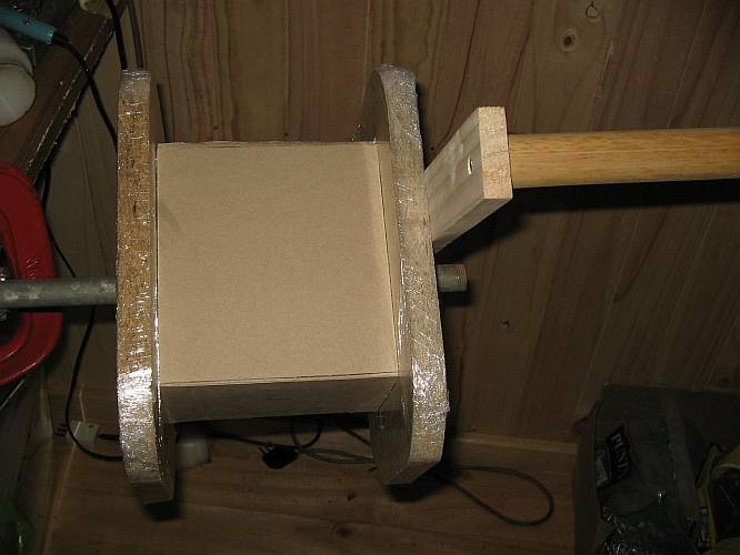
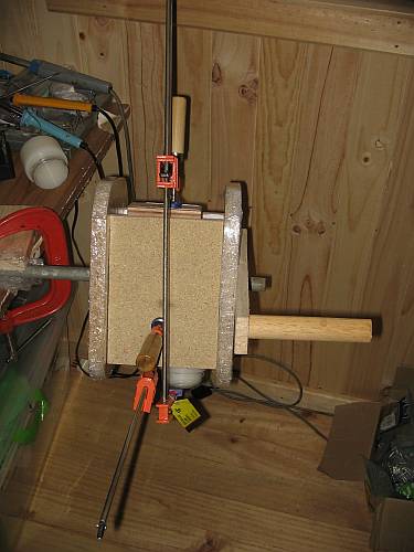
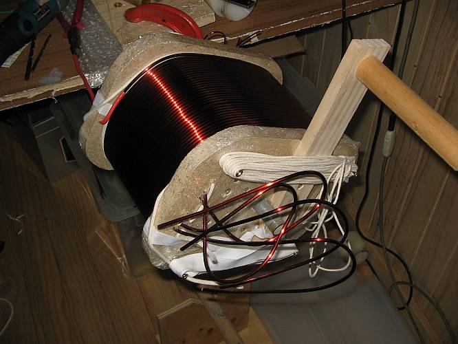
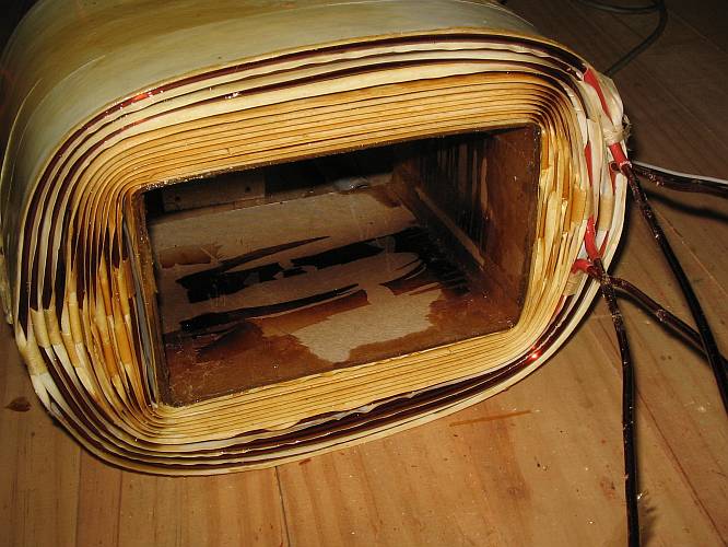
I do have a transformer winding machine, a gift of my friend Enrique from many years ago, but for this large transformer (10kVA), the machine was too small. So I crafted this setup to wind the transformers: A simple wooden form with a crank on it, mounted on a steel tube clamped to my desk. Below it is a support for the wire coil. The wooden form is designed in such a way that the pieces can be individually removed once the winding is complete. Each wooden piece was individually wrapped in several layers of kitchen plastic wrap, to act as a demoldant and keep the impregnation varnish from sticking to the wood.
The bobbin for the transformer was made simply from two U-shaped pieces of 1.5mm thick Pressspan. For those of you who don't know it, this is simply a very hard and stiff cardboard. It's antique, and only rated for class B (that tells how much heat it survives), but I couldn't get anything better for the purpose. Since it will be serving mostly a structural purpose, it's OK despite the fact that the rest of the transformer is built with class F materials.
The two U pieces are epoxied together, and compressed to keep them from buckling.
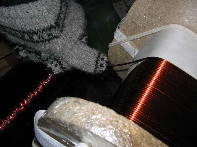
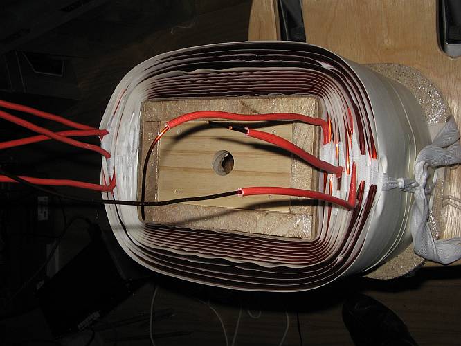
Two layers of class F insulating material were wound on the bobbin. I used 0.19mm thick Nomex-Mylar-Nomex laminate. Then the high voltage winding was made, in eight nice layers, with one sheet of NMN laminate between each layer and the next. To keep the wire from buckling out during winding, it has to be pre-formed in the opposite sense while winding, as shown here. I used wool gloves, to avoid wearing through my poor thumb!
The first layer of the high voltage winding is ready. Cotton rope is used on each side to keep the wire from getting near the edges. This rope is later removed. The flat cotton straps instead, which bind the wire turns together and keep the whole thing from falling apart once the form is removed, remain in place.
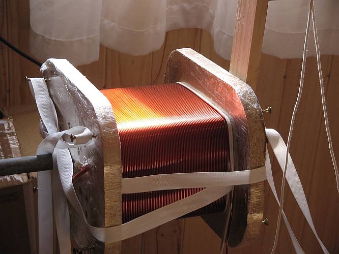
The work is simple, but a bit exhausting when it comes to the low voltage winding, which uses quite thick wire that's not easy to bend into the proper shape. Anyway, here you can see the completed winding, with the last layer of the low voltage winding showing, prior to installation of the protective cover, made from several layers of NMN laminate.
Note the many wires coming out of the form. There are eight wires from the low voltage side, and four on the high voltage side. This is because each winding is made in two halves to provide a center tap, and because there are actually two low voltage windings, which allow configuring the transformer for different modes of operation.
The moment of truth: When opening the form, will the winding hold together, or spring apart?
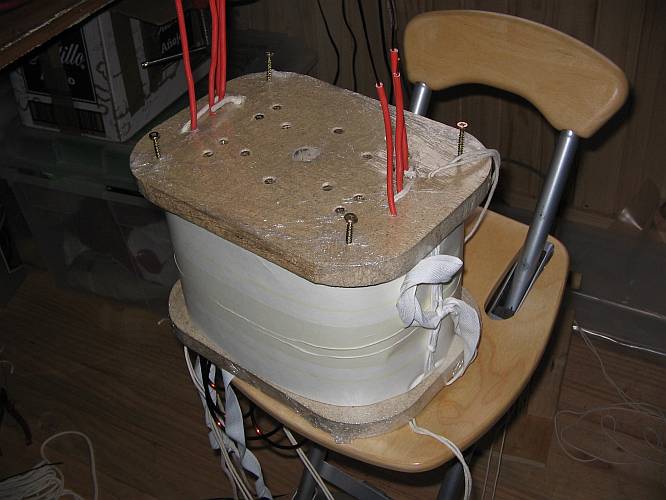
It holds together, fortunately. In this picture it's shown ready for impregnation. Only the top cover of the form has been removed, and the bottom side has been sealed with some more kitchen wrap. I then applied the impregnation varnish by simply pouring about two liters of it into the winding. It will soak into the Nomex, wet and cover every piece of wire, gluing everything firmly together, moisture-proofing it to some degree, improving the insulation, and aiding thermal transfer.
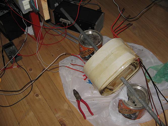
The varnish I used is intended for oven-drying at 140 to 150 degrees Celsius. I don't have an oven large enough to fit this coil, so I heated it by applying roughly 20A of direct current to the high voltage winding. I monitored the temperature by measuring the resistance change of the wire.
After drying the varnish and removing the wooden form, the coil assembly feels as solid as a rock. There are some remains of roasted kitchen wrap, which look ugly black, but otherwise the only dark color comes from the varnish.
As a last step, the voids left by the cotton rope are filled with neutral-curing silicone sealant, which is an excellent insulator and will survive the high temperature this transformer might attain. I didn't do a particularly beautiful caulking work here, but technically it's good enough.
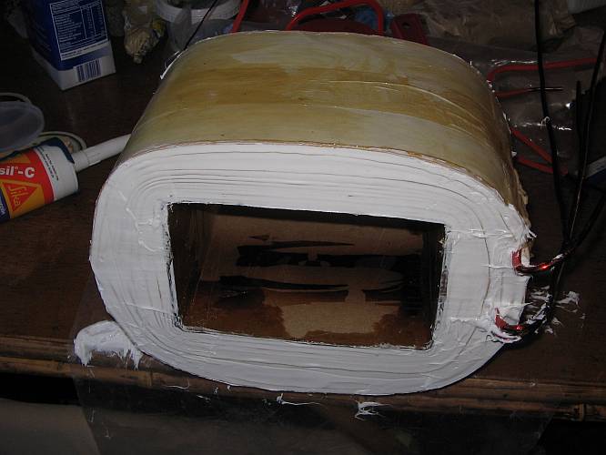
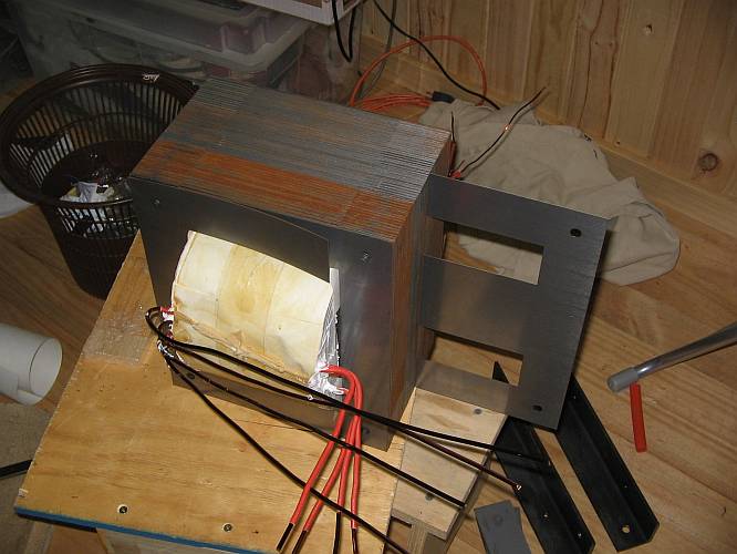
The core is now assembled.
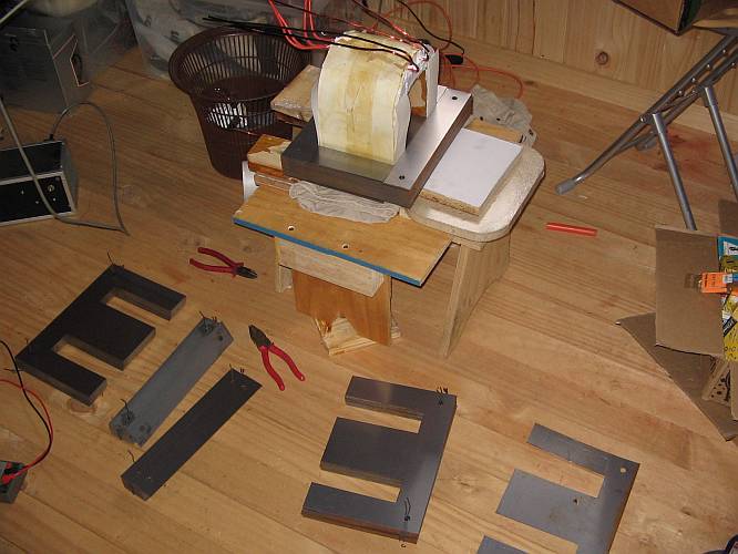
Inserting the very last E!
Then the steel angle pieces and bolts were installed, taking care to properly insulate everything, to avoid unnecessary losses and heating. I even insulated the holes through which the bolts go!
At this point we could say that the transformer is ready and fully functional. The only job that remains to be done is dressing the connection wires.
And now it's really ready! And then I had to make the other one...
![]()
After finishing the second transformer, the big job that remained was moving one of the transformers down to the machine house. My friends from Temuco were planning to come over and help me, when suddenly, out of the blue, my long missing neighbor Gabriel showed up. He had heard the turbine running (it's right across the fence from his property), and seen the outflow, so he knew it was finally running, and wanted to see it in detail, to enjoy at least a little bit of satisfaction from his hard work. I told him about the transformers, and he proposed to immediately bring down one of them. Why not? So I went for my pry bar, to use it to carry the transformer, which at its 92kg of weight can be carried by two people without too much trouble. But Gabriel will ever be Gabriel. "92 kilos? I can carry that alone! Don't bother with your pry bar." And so he did!
This trip made Gabriel remember the many others down this slope, with the wheelbarrow full of gravel and sand.
Provisionally the transformer was seated on some wooden pieces, to keep it clear of possible minor flooding. The conduits with the high voltage wires were fixed in such a position that in the event that condensation accumulates and drips out, it won't drip onto the transformer. Also, the wires have drip loops and are in free air, so that there is no insulation problem. But anyway, at only 1000V each against earth, insulation isn't really a problem. The center tap of the high voltage winding is grounded.
The other transformer was installed on a small wooden pad on concrete blocks, next to my little cabin. Later it will be installed indoors in the definitive round house.
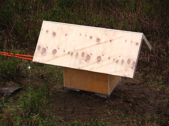
For weather protection, this transformer got a nice doghouse-style structure over it. It's sheeted in thin polyethylene, which should hold up long enough ( a few months) until the transformer can be moved to the round house. The roof of the doghouse seems oversized, but I did that because in the apexes of the sides there are ventilation openings, and I don't want the wind to blow rain into them. These openings, and also the big one below the transformer, are covered with wire mesh against rats, insects and birds.
With the transformers in place, I could enable an additional nozzle at my turbine, so it's running on two large and one small nozzle now, generating a tad over 4000 watts in this configuration, and consuming 30 liters per second. Extrapolating, and considering the losses, with the four large nozzles (its maximum configuration) it should reach very close to 7000 watts, at 48 liters per second. Not bad for a microhydro installation conceived for a baseline power of 5kW, with any extra being welcome. And there still is the possibility of installing even larger nozzles and running higher power. The penstock was designed for 70 l/s, and the turbine is supposed to accept nozzles of up to 34mm diameter, while my "big" ones now are 27mm. At the higher flow, the penstock loss would become noticeable (it's almost unmeasurable now), so the power increase wouldn't be that large, but it might be possible to coax the system up to 9kW, which would be pretty much at the limit of the 10kVA rating of the generator and the transformers.
For now, however, I won't do it, because the 4kW generated at this time provide ample power to my little cabin, including very comfortable heating while on the outside it's below freezing. So I will stay at 4kW for some more time, maybe until next winter, when I will be living in the big round house, and needing more power.
The frequency is keeping very stable at 49.5Hz. When I next remember bringing a small insulated screwdriver along, I will correct it to 50Hz. The voltage is a bit less stable, as the AVR has some temperature dependance. In this photo it's particularly low, because I was testing the system disconnected from any external load, with the 4kW being dissipated inside the machine house, so it was very warm there. But normally the voltage stays between 224 and 228V. Which means that after the drop in the transmission line and transformers, I end up with 220-224V at my cabin, which is much more stable than what the public grid can provide!
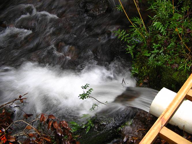
This is the outflow from my turbine, at 30 l/s. Poor tired water, depleted of most of its energy! :-)
The switching of the TRIACs in the ELC, coupled with the inductance of the generator, causes some significant distortion to the waveform:
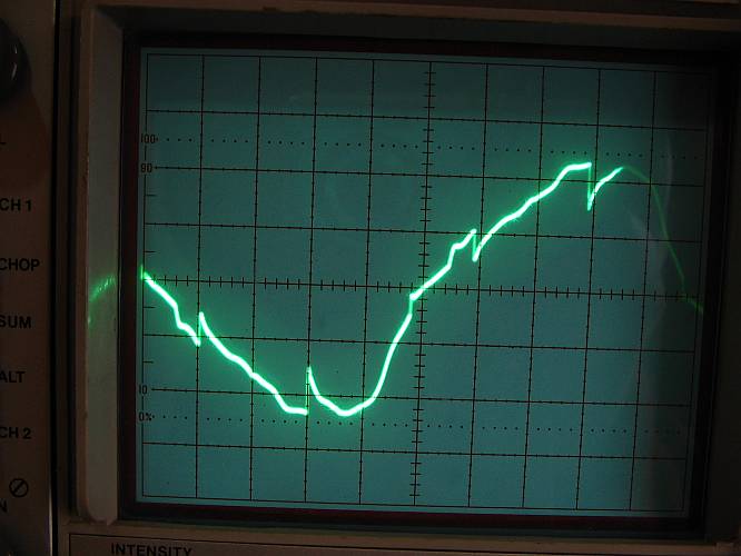
To get rid of at least the hardest flanks, I installed a 20uF capacitor in parallel with the generator. This is the result:

It's not perfect, but workable. Anyway, later on I will build a more sophisticated ELC, using high frequency pulse width modulation, with full filtering. Until then, I can live with this slightly distorted waveform.
After all this work, I celebrated with a turbine-styled apple pie! After making this photo, it was baked in my electric oven, using microhydro power, and eaten along with tea brewed using an electric kettle powered by microhydro, in a house heated by microhydro and lit by microhydro too, while some beautiful Schütz music was playing in the microhydro-powered music equipment. Ah, that's life!

After close to a year using the system in the configuration shown here, I added a new ELC installed at the home, that distributes the power optimally among several useful loads. If you are electronically inclined, have a look at my homemade ELC, and general ELC discussion!
Back to Implementing my paradise.