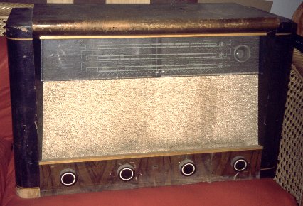
Philips 916 X-10
 One good day a
work mate approached me with the good news that he had an old radio that
may interest me. He played it down, telling me that it was in bad shape,
but maybe I could use it for parts. And then he brought me this somewhat
damaged and dirty, but nevertheless beautiful sample of early post-war
Dutch technology!
One good day a
work mate approached me with the good news that he had an old radio that
may interest me. He played it down, telling me that it was in bad shape,
but maybe I could use it for parts. And then he brought me this somewhat
damaged and dirty, but nevertheless beautiful sample of early post-war
Dutch technology!
The Philips collectors among you probably know that the first figure
in the Philips model number indicates the quality level of a set. Well,
this is a 9! It's the top-of-the-line table radio of 1947! It employs a
rather complicated circuit, with a pentode RF preamplifier (EF9), a separate
oscillator and mixer in a triode/hexode combination tube (ECH4), then comes
an IF amplifier and detector using an EBF2, followed by a pentode (!) audio
preamplifier (another EF9), and the audio power amplifier with Philips'
well known and much feared multiple feedback (EL3). The rectifier is an
AZ1 with a 4V filament, and of course there is a dual-action magic eye
(EM4)! The radio offers continuous coverage from 520kHz to 22MHz in three
bands, loudness compensation, and delayed action dual AGC! The tuning mechanism
employs a clever automatic reduction drive that serves as a bandspread
for short wave.
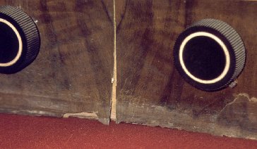 This radio definitely
had seen better days. This close-up photo shows the sorry condition of
the palisander veneer around the knobs! Like in almost all old radios,
the rubber feet had decomposed, leaving this radio sitting on its belly,
and apparently its bed for many years was a damp cellar floor. Humidity
crept up, fouled the wood, loosened the glue, and pushing the radio around
without lifting it didn't make things better. Oh well, that's how a discarded
radio's life used to be like...
This radio definitely
had seen better days. This close-up photo shows the sorry condition of
the palisander veneer around the knobs! Like in almost all old radios,
the rubber feet had decomposed, leaving this radio sitting on its belly,
and apparently its bed for many years was a damp cellar floor. Humidity
crept up, fouled the wood, loosened the glue, and pushing the radio around
without lifting it didn't make things better. Oh well, that's how a discarded
radio's life used to be like...
I tried hard to get some spare palisander veneer, but didn't find any.
Faced to the decision of replacing it by some different wood, or trying
to preserve it, I opted for the latter. I glued back on whatever was left
of the palisander, and filled the gaps and edges with a tinted wood filler.
The result is far from perfect, but if some day I find a better way to
fix this, at least all original wood I got is still there.
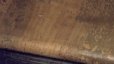 But heavy rotting
was not the only problem. Termites had attacked this radio! They were unable
to eat through the very hard palisander, or perhaps it just tastes bad,
but they ate up almost all of the soft wood below, and made lots of tunnels
through the veneer on the radio's top, which seems to be makore wood. On
this close-up photo you can see a few of the hundreds of termite holes
I had to patch! By the way, you can also see how little of the original
finish remained in place. This radio was in for a total stripping and refinishing,
no doubt.
But heavy rotting
was not the only problem. Termites had attacked this radio! They were unable
to eat through the very hard palisander, or perhaps it just tastes bad,
but they ate up almost all of the soft wood below, and made lots of tunnels
through the veneer on the radio's top, which seems to be makore wood. On
this close-up photo you can see a few of the hundreds of termite holes
I had to patch! By the way, you can also see how little of the original
finish remained in place. This radio was in for a total stripping and refinishing,
no doubt.
But first I had to get rid of the termites. They were still alive and
happily eating my radio! And I didn't want them to spread into my other
radios, furniture, the floor... So the first thing to do was removing everything
nonwooden, then packing the cabinet into an hermetically sealed plastic
bag, and breaking an ampoule of lindane inside. That's a very strong poison,
and pretty much the only poison powerful enough to get rid of these radio-eating
beasts! I left the radio in the bag for an entire month, so the toxic gases
could thoroughly impregnate the wood and kill off all the insects. Then
I opened the bag, caring for ample ventilation in order to avoid following
the termites into the grave, and let the radio exude the odor for another
month. Only then could the repair work start.
 Meanwhile I
started the electronic repair. This radio had gone through several repairs
during its lifetime, obviously showing that all efforts had been made to
keep it running in times when spare parts were hard to get. The best example
of this can be seen in this photo. At some time the output tube failed,
and some radio technician, unable to find an EL3, simply used the ubiquitous
EL84, a very much more modern tube with miniature pinout. He cut the base
from an old P-type tube, mounted a miniature socket on top of it, and inserted
the EL84. He did not touch the wiring, so returning the radio back to original
condition was as easy as locating an original EL3, and plugging it in! Actually
the tube I got is an EL3N, an improved and slightly fatter version of the EL3.
If you ask me, it's close enough!
Meanwhile I
started the electronic repair. This radio had gone through several repairs
during its lifetime, obviously showing that all efforts had been made to
keep it running in times when spare parts were hard to get. The best example
of this can be seen in this photo. At some time the output tube failed,
and some radio technician, unable to find an EL3, simply used the ubiquitous
EL84, a very much more modern tube with miniature pinout. He cut the base
from an old P-type tube, mounted a miniature socket on top of it, and inserted
the EL84. He did not touch the wiring, so returning the radio back to original
condition was as easy as locating an original EL3, and plugging it in! Actually
the tube I got is an EL3N, an improved and slightly fatter version of the EL3.
If you ask me, it's close enough!
But this wasn't the only change. The original EF9 RF preamp tube had
been replaced by an EF6. While they look alike and are pin-compatible,
they behave very differently! The EF9 is a variable transconductance pentode
designed for using AGC, while the EF6 is a sharp-cutoff pentode designed
for fixed-bias applications! Of course, this made the AGC of the first
stage work very badly, and the genius who did the tube replacement opted
for simply eliminating that AGC!!! He did it so nicely that I was puzzled
for over a year, until finding out! One level of AGC, at the IF tube,
remained, so the radio basically had some AGC, but not nearly enough. I
had to connect the antenna for short wave listening, and unplug it for
medium wave reception, otherwise the radio overloaded and distorted badly
on strong local stations.
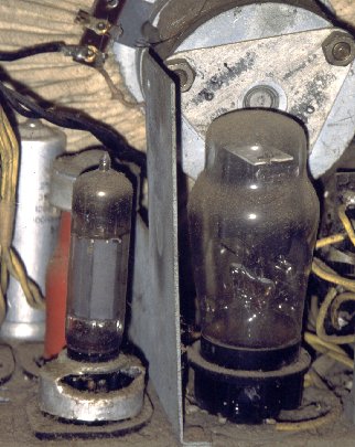
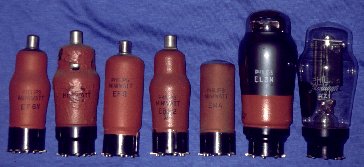 Here is the
full tube complement of the radio. The EL3N is new, added by me to replace
that ugly EL84. The other tubes are those that were in the radio when I
got it. However, later I replaced the EF6 by a real EF9, and I also had
to replace the magic eye, which was badly worn. I found exact original
replacements for all of those!
Here is the
full tube complement of the radio. The EL3N is new, added by me to replace
that ugly EL84. The other tubes are those that were in the radio when I
got it. However, later I replaced the EF6 by a real EF9, and I also had
to replace the magic eye, which was badly worn. I found exact original
replacements for all of those!
American collectors may not be familiar with these tubes' sockets. They
have no pins, but side contacts! These are the famous P-type sockets, in
use in Europe from the late 1930's through the late 1940's, and for some
specific tube types even into the 1950's! This radio is particularly
nice in that it employs a complete series of P-type tubes!
The crumbled paint on the oscillator/mixer tube is due to some grease
from the variable capacitor creeping onto it and attacking the paint. However,
the tube is in good condition. The red paint on the tubes gives these old
Philips radios a real touch of class! :-)
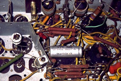 Look closely
at this photo. Note the trimmer soldered over the coil base, and note the
square coil shield clamped with a capacitor bracket. This is yet another
modification the radio underwent! The broadcast band oscillator coil must
have failed, and instead of fixing it, some technician simply removed it,
and used a totally different, newer and much smaller coil - the one you
see here. The modification works correctly, so I did not change it, but
I would love to get an original Philips oscillator coil, to patch the gaping
hole in the chassis!
Look closely
at this photo. Note the trimmer soldered over the coil base, and note the
square coil shield clamped with a capacitor bracket. This is yet another
modification the radio underwent! The broadcast band oscillator coil must
have failed, and instead of fixing it, some technician simply removed it,
and used a totally different, newer and much smaller coil - the one you
see here. The modification works correctly, so I did not change it, but
I would love to get an original Philips oscillator coil, to patch the gaping
hole in the chassis!
Note those black paper capacitors in the upper part of the photo. They
are encased in tar, and all of them were leaky. After the first
one burnt up, I got the message and replaced them by plastic caps. I left
the original ones in place, disconnected, and hid the plastic caps behind
them, as well as possible. The same was true for all electrolytic capacitors:
Not one was still usable.
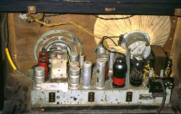 Here's the
inside of the radio, after repair. The white (well, sort of white) cloth
over the speaker adds to the typical Philips look. I could not wash this
cloth, it was much too damaged. So I kept it in original, dirty condition!
Here's the
inside of the radio, after repair. The white (well, sort of white) cloth
over the speaker adds to the typical Philips look. I could not wash this
cloth, it was much too damaged. So I kept it in original, dirty condition!
But before I arrived at this stage, another hard work had to be done:
The audio stage was distorting badly. I traced the problem to an open feedback
winding in the output transformer. Now this is really bad news! There is
no way to get such a special audio transformer nowadays: It has a primary
winding, a secondary winding, a compensation winding, and two independent
feedback windings, all of very specific characteristics. And it is potted
in tar, sealed into a soldered steel box! I know of no other hobby collector
who even attempts to fix such a case... But I did! Yes, I know, I'm stubborn!
So, I removed the transformer from the radio, unsoldered the steel box,
took the tar clump out, melted it, poured the tar off, collecting it in
a tin. Then I disassembled the iron core, and started opening the windings.
Well, you probably know that audio transformers use to have many thousand
turns of very thin wire, and I was fully expecting having to unwind and
rewind the entire thing. But then a large dose of luck came to my help:
The bad winding was the uppermost one! I removed the 520 turns of #46 wire...
yes, 46-gauge! It's much thinner than a human hair!!! Of course, I could
not get it off in one piece, I rather had to remove it in chunks, and then
do some detective work to determine the amount of turns. Then I made the
new winding, using #42 wire, which was the thinnest I could get. Fortunately,
there was enough space.
Before repotting the transformer, I tried it in my radio. I had written
down all connections, but of course I could not know the proper phasing
of the repaired feedback winding. So I just picked a phasing, and of course,
by Murphy's law, got it wrong and produced an audio oscillator instead
of a radio. Then I inverted the winding, and.... wow! This radio
has the best sound of all in my collection!!!
But I like things in the original way. So I had to repot the transformer.
I placed it in its steel box, and heated the tar. I warmed the transformer
too, so the tar would not solidify too quickly. I heated the tar quite
a lot, so it would flow nicely, and I warn you that this is a stinky business.
Then I poured it into the steel box, but some vapor caught the flame,
and immediately I had a burning torch! I ran with the burning transformer
into the kitchen, grabbed some aluminum foil and used it to asphyxiate
the fire. No damage had been done, just a very small amount of the tar
had burnt away. But the smell!!! Running through the entire home leaving
a black cloud of tar smoke behind was a dumb thing to do! It took half
a year to get that hellish smell out of my home! Everything had soaked
up that stink!
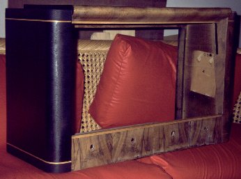 So, here is
the cabinet. After killing the termites, I sucked their remains away using
a vacuum cleaner applied to the holes. After this procedure, the cabinet
was extremely lightweight! There was almost no wood remaining below the
veneer. I had to fill it with epoxy resin. I used more than one liter of
resin! Then I filled the damaged areas at the outside, like the lower black
rounded corner in this photo. The stripping was done next, followed by
applying carbon-based black paint to the sides, leaving two natural colored
strips free of carbon. This photo shows the cabinet when one side already
had its black cover, while the other bears only remains of the original
paint, left over from the stripping process.
So, here is
the cabinet. After killing the termites, I sucked their remains away using
a vacuum cleaner applied to the holes. After this procedure, the cabinet
was extremely lightweight! There was almost no wood remaining below the
veneer. I had to fill it with epoxy resin. I used more than one liter of
resin! Then I filled the damaged areas at the outside, like the lower black
rounded corner in this photo. The stripping was done next, followed by
applying carbon-based black paint to the sides, leaving two natural colored
strips free of carbon. This photo shows the cabinet when one side already
had its black cover, while the other bears only remains of the original
paint, left over from the stripping process.
After all black paint had been applied, I simply brushed shellac over
this radio. The original finish was sprayed lacquer, but considering that
my repair of the palisander area is very provisional, and I intend to redo
it in some better way, I applied just the easily removable shellac. If
I, or someone else, one day decides to make a better repair, at least it
will be possible to remove the shellac easily and without any further damage.
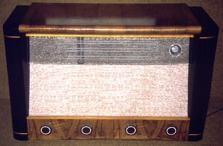 And this is
the end result. The main weak spots are the patched, but not really repaired
palisander veneer at the bottom, and the disaster that happened with the
speaker grille cloth. Yes, it was a real disaster! The first photo on this
page lets you see how dirty it was. And it was firmly glued to a backing
plywood plate. So, at first I tried to use carpet cleaning foam to get
the dirt off. It did not help at all. So, I had to undertake the risky
business of removing the already damaged cloth from the wood, and wash
it. I soaked wood and cloth in water, which loosened the glue, so I could
remove the fabric. I then washed it in cold water, using mild detergent,
being very careful because the fabric was really weak, sunburnt and thinned.
The dirt came off nicely. Then I stretched it as much as it would go, because
it already looked much smaller than it had been! But I couldn't stretch
it much, because it was almost ripping. Once it had dried, the nasty surprise
came: The fabric had shrunken so much that there was no way to cover the
entire opening!
And this is
the end result. The main weak spots are the patched, but not really repaired
palisander veneer at the bottom, and the disaster that happened with the
speaker grille cloth. Yes, it was a real disaster! The first photo on this
page lets you see how dirty it was. And it was firmly glued to a backing
plywood plate. So, at first I tried to use carpet cleaning foam to get
the dirt off. It did not help at all. So, I had to undertake the risky
business of removing the already damaged cloth from the wood, and wash
it. I soaked wood and cloth in water, which loosened the glue, so I could
remove the fabric. I then washed it in cold water, using mild detergent,
being very careful because the fabric was really weak, sunburnt and thinned.
The dirt came off nicely. Then I stretched it as much as it would go, because
it already looked much smaller than it had been! But I couldn't stretch
it much, because it was almost ripping. Once it had dried, the nasty surprise
came: The fabric had shrunken so much that there was no way to cover the
entire opening!
I could not get any replacement fabric that looked reasonably alike.
So I glued it back on, for the moment at least, but at the top you can
see the frayed edge. If anyone can get me a piece of original 1947 Philips
speaker grille cloth, I would be thankful! My e-mail address is on the
main homo ludens page!
This radio is now 100% usable and very enjoyable. It has a great sound,
and an incredible sensitivity! It hears the entire world, 24 hours a day,
using just a 1m long piece of wire as an antenna! It actually hears well
enough to enjoy music on short wave! Even my modern Kenwood doesn't do
that!
My thanks go to Ramón Huidobro for giving me this radio, and
to Gerard Tel for getting me some info on this set and helping me understand
what had happened to it.
Update:
More recent research seems to make this radio a little bit older than I
originally thought. It seems that Philips kept producing radios all through
the war, with a high end line including the models 914X and 915X from 1940
to 1942, and the 916X from 1943 to 1945. At least, other collectors say this.
Indeed, recently I saw Philips radios made in 1947 that use the newer line
of tubes! As a consequence, I would re-date this 916X-10 export model to 1945,
just when international business could (and needed to!) resume, and before
Philips could switch to the newer tubes.
Back to the homo ludens radiohistoricus
page.