The story of
homo ludens radiactivus
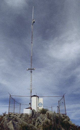
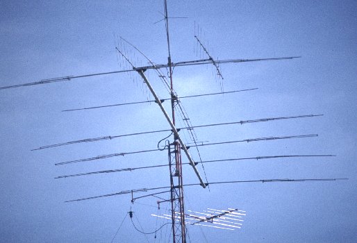 There are two classes
of people in this world: Those who shudder when seeing such an ugly kludge
of aluminum, iron, copper and plastic obscuring the sky, and... well...
radio amateurs, lovingly called "hams"! I definitely belong to the second
class of people. You may call me XQ6FOD instead of using my name. If you
want we can talk in Morse code, for even if I don't like it at all, I had
to learn it, and, please, don't ever try to tell me that my antennas
are ugly! By the way, these are not mine, they belong to Claudio Santander,
CE5SG. My antennas include an azimuth-elevation rotator with a large satellite
antenna too. Just a little bit more iron on the roof...
There are two classes
of people in this world: Those who shudder when seeing such an ugly kludge
of aluminum, iron, copper and plastic obscuring the sky, and... well...
radio amateurs, lovingly called "hams"! I definitely belong to the second
class of people. You may call me XQ6FOD instead of using my name. If you
want we can talk in Morse code, for even if I don't like it at all, I had
to learn it, and, please, don't ever try to tell me that my antennas
are ugly! By the way, these are not mine, they belong to Claudio Santander,
CE5SG. My antennas include an azimuth-elevation rotator with a large satellite
antenna too. Just a little bit more iron on the roof...
This is the most fascinating hobby I have, and it will be for life,
so much is sure. There is just so much to explore. But before starting
that, let me tell you about the history of my ham career. It may show you
how much fun I have had, and above all, how many hours I have spent on
this hobby! Be patient, this story is several dozen photos long, plus the
text, so if you have a slow connection it will take some time to fully
load. I hope it will be worth it.
How it started
I felt attracted towards technical things since I was very small. Let it
suffice to say that I installed electrical lighting in my sister's doll
house, electrified my mother with a coil and battery, built a steam turbine
that soon had the condensation running down the walls, all before I was
eight years old. By the time I was eleven, I had built electric signaling
systems, several electric motors, an improved steam engine, coupled it
to my bicycle's dynamo, and despite this self generated power I was increasing
my battery consumption at an alarming rate. Oh yes, plus the candles used
for the steam engine's boiler...
It was in this promising time when I reached my twelfth birthday. My
parents had the marvelous idea of giving me a "KOSMOS Radiomann" set. That's
a german educational game. It's just a box containing a few resistors,
capacitors, a bulb, battery, a diode, two coils, some wire, and even a
real transistor, mounted on a yellow plastic base! It also included all
necessary connection material, a childproof protoboarding system, and an
instruction booklet that described over one hundred experiments to be done
with these parts, starting from the taste of electricity (put a 4.5V battery
against your tongue, try it!), electricity out of a lemon, an AM radio,
right through a spark transmitter with coherer receiver! I was in heaven.
This game taught me more electronics than the entire university career
did, several years later!
Shortly later, in an hobby exhibition, I discovered the booth of the
Radio Club Concepcion. It was my first contact with ham radio. People there
were very friendly, starting with whom would become my long-time tutor
in ham radio, Emilio Troncoso, XQ5BIB. Shortly later my father and I were
invited by Enrique Oelker, CE5DF, my father's friend, to come over and
visit his radio station. I still remember that visit, how that very kind
man switched on his radios, commented that the conditions on that saturday
morning weren't so good, switched on a linear amplifier containing a radio
tube larger than I had ever seen or even imagined, called a few times,
and got answer from a ham in Germany. Wow! There he was sitting back in
his chair, talking to a friendly guy 10.000 km away, across oceans and
continents, as easy as that! You must keep in mind that this happened years
before home computers and internet, even years before any affordable and
reliable long-distance telephone service, at least in this part of the
world. My father seemed more interested in the huge collection of
classical music that was in the same room, but I could hardly get my eyes
away from that radio! My spark transmitter reached 10 meters, and this
thing, not so much larger, covered a million times more!
The next day I biked to the Radio Club, and became a student member.
Apparently the youngest member in its history. But they had bad news for
me: Chilean regulations of that time set a minimum age of 15 years to get
the simplest ham license! I fell short of that, by what seemed an eternity.
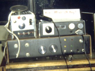 So, being too young
to use radios, instead I learned to build them. First of all I built an
adjustable, reasonably regulated power supply, that delivered 0-15 Volt
at about 1 Ampere. It's the one on the upper left in this photo. I built
the box from 1 mm aluminum sheet, and lacking any decent tools, made the
holes with hammer and nails... The transformer, hand-wound of course, was
glued in, as it lacked any screw holes. This power supply had to be kept
in upright position at all times, otherwise the transformer could have
fallen off and smashed the other parts... I remember how it took several
days to convince my mother to let me plug it in.
So, being too young
to use radios, instead I learned to build them. First of all I built an
adjustable, reasonably regulated power supply, that delivered 0-15 Volt
at about 1 Ampere. It's the one on the upper left in this photo. I built
the box from 1 mm aluminum sheet, and lacking any decent tools, made the
holes with hammer and nails... The transformer, hand-wound of course, was
glued in, as it lacked any screw holes. This power supply had to be kept
in upright position at all times, otherwise the transformer could have
fallen off and smashed the other parts... I remember how it took several
days to convince my mother to let me plug it in.
Under Emilio's instructions I put together a low power direct conversion
transceiver for the 40 meter band. It could run double sideband or continuous
wave. That's the big thing under the other boxes. It featured a Hartley
variable frequency oscillator. The receiver comprised a 2N2222 RF preamplifier,
an MPF102 mixer, a 741 opamp audio amplifier and an LM380 power amplifier.
It worked, but had lousy sensitivity. Anything below S9 got swamped by
the noise. The transmitter was quite decent, having another 741 as a microphone
amplifier, a two diode balanced mixer, and three RF stages ending in a
class-A power amplifier built around two 2N3553 transistors. Note that
these are UHF devices! At least they did RF...
This radio was built on a style of crude circuit board: I cut a piece
of chipboard, glued small scraps of copper foil to it, and soldered the
components to those copper spots. I must confess, I had not yet discovered
that it was allowable to cut the leads of the parts, so every resistor
and every capacitor was soldered with full lead length! The IC pins were
soldered to wires, to make them long enough. It was a mess, but it worked!
Unfortunately I have no photo of it...
As I had no license to actually put this radio on the air, I asked Emilio
to test it for me. He did, it worked, but suddenly he was holding a knob
in his hand. He teased me for several years with this! I could build a
functional transceiver, but I could not fasten the screws of the knobs!
Bored by waiting for my 15th birthday, I temporarily turned my back
to ham radio and built the third thing you can see in the photo: A citizen's
band transceiver based on a surplus board. I basically put it into a homemade
enclosure (this time I did fasten the screws!), cabled and adjusted it.
It worked very well, putting out 4 Watt in AM, on all 40 channels.
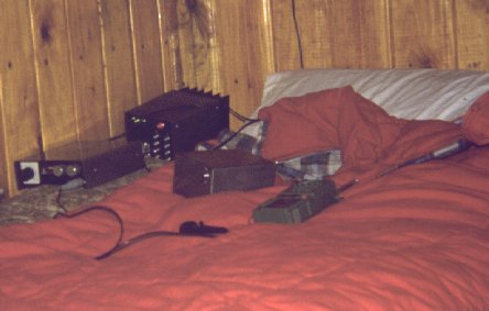 I used this radio
a lot! I made dozens of friends on CB. This was the time of the CB boom
in Chile, and that band was boiling with activity. No license was really
required, everyone just used the band. This photo shows my bed station
in a summer cottage where I often went. The bed was a two-story affair,
my brother slept below me, and I had to share my mattress space among the
sleeping bag and the radio station. Note that the station is more complete
already: A large 13.8 V, 15 A power supply has been added. The box in the
middle is a battery case containing 10 NiCad cells. So I could put the
line-fed power supply away from the bed before sleeping. And yes, I slept
with my radio...
I used this radio
a lot! I made dozens of friends on CB. This was the time of the CB boom
in Chile, and that band was boiling with activity. No license was really
required, everyone just used the band. This photo shows my bed station
in a summer cottage where I often went. The bed was a two-story affair,
my brother slept below me, and I had to share my mattress space among the
sleeping bag and the radio station. Note that the station is more complete
already: A large 13.8 V, 15 A power supply has been added. The box in the
middle is a battery case containing 10 NiCad cells. So I could put the
line-fed power supply away from the bed before sleeping. And yes, I slept
with my radio...
The toy walkie-talkie was used as a portable, to communicate to my "big"
CB rig. It transmitted on channel 14, and received the entire band, with
no selectivity at all, due to its regenerative receiver. Sometimes I was
so generous that I even let my little brother use the portable!
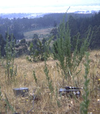 The battery pack
was also often put to good use during portable operation. I climbed every
hill within a distance reachable by bike or on foot, searching for the
sweet spot that would put my tiny signal across the oceans. I contacted
Europe, North America, even a few asian stations, all with 4 Watt on AM
and a vertical dipole strung in any convenient tree! Brazil and Venezuela
were everyday contacts.
The battery pack
was also often put to good use during portable operation. I climbed every
hill within a distance reachable by bike or on foot, searching for the
sweet spot that would put my tiny signal across the oceans. I contacted
Europe, North America, even a few asian stations, all with 4 Watt on AM
and a vertical dipole strung in any convenient tree! Brazil and Venezuela
were everyday contacts.
Did you notice the microphone? I had no money for fancy things. All
was financed by a rather thin allowance. That microphone was the very cheapest
I could find... It worked. Don't ask for more.
 Very often I got
help from classmates, neighbor kids, other friends. Here you can make the
acquaintance of Antonio Diaz, who helped me carry the gear up some hills
and was setting up the station here. He was into technical things too,
being the first among my buddies to get a programmable calculator! I remember
that Casio, I think it was an FX702, programmable in BASIC language. Wow!
He was our computer genius, and I learned my first steps in BASIC on his
machine.
Very often I got
help from classmates, neighbor kids, other friends. Here you can make the
acquaintance of Antonio Diaz, who helped me carry the gear up some hills
and was setting up the station here. He was into technical things too,
being the first among my buddies to get a programmable calculator! I remember
that Casio, I think it was an FX702, programmable in BASIC language. Wow!
He was our computer genius, and I learned my first steps in BASIC on his
machine.
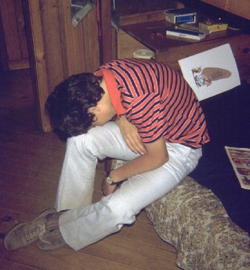 But such mountaineering
trips cost a lot of effort! He barely made it back... And I didn't feel
like going out again either. We were 14 years old by that time, full of
energy, full of desire to get out higher, farther, greater, longer, wider,
but sometimes the desire was just a tad larger than the energy...
But such mountaineering
trips cost a lot of effort! He barely made it back... And I didn't feel
like going out again either. We were 14 years old by that time, full of
energy, full of desire to get out higher, farther, greater, longer, wider,
but sometimes the desire was just a tad larger than the energy...
Note the multimeter and tools on the bench in the back, behind the Asterix&Obelix
magazine.
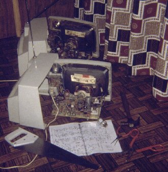 I was getting confident
enough in my skills to start repairing things for money. But it was not
often that I got two TVs of the same model for repair, at the same time!
These hybrid "Antu" TVs were still common in Chile. I took the opportunity
to make a photo, showing the tools used for the task, like a hammer, and
a hacksaw. I used this photo to shock my classmates...
I was getting confident
enough in my skills to start repairing things for money. But it was not
often that I got two TVs of the same model for repair, at the same time!
These hybrid "Antu" TVs were still common in Chile. I took the opportunity
to make a photo, showing the tools used for the task, like a hammer, and
a hacksaw. I used this photo to shock my classmates...
The business soon flourished. I charged little money, and most often
I could repair the equipment. If I couldn't, for whatever reason, of course
there was no charge. This type of warrantee brought me lots of clients,
and the income was very welcome to finance both the radio hobby, and photography,
which was eating up lots of money by that time.
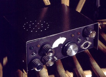
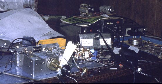 This photo shows
my radio station a few months later. I was now 15 years old! I had registered
for my ham exam that same day, and soon was the holder of my first real
ham radio novice license! I got the callsign CE5FOD. This event caused
an equipment building rush, as I noticed that my first radio was just too
deaf for any decent work. And the long-legged parts often came loose. So,
I finally disassembled that thing and started building a new, much improved
radio, reusing the same parts. That's the metal thing you see on the left.
It was ready, except for the cabinet. And it worked great! I photographed
it after the first contact.
This photo shows
my radio station a few months later. I was now 15 years old! I had registered
for my ham exam that same day, and soon was the holder of my first real
ham radio novice license! I got the callsign CE5FOD. This event caused
an equipment building rush, as I noticed that my first radio was just too
deaf for any decent work. And the long-legged parts often came loose. So,
I finally disassembled that thing and started building a new, much improved
radio, reusing the same parts. That's the metal thing you see on the left.
It was ready, except for the cabinet. And it worked great! I photographed
it after the first contact.
Note the new SWR meter. Behind it is a new 0 to 15 V, 3 A power supply,
with full short circuit protection. On top sits a chipboard based antenna
tuner, and the small knot of parts in front of the SWR meter is a 30 Watt
power amplifier! The station was quite usable, despite the look!
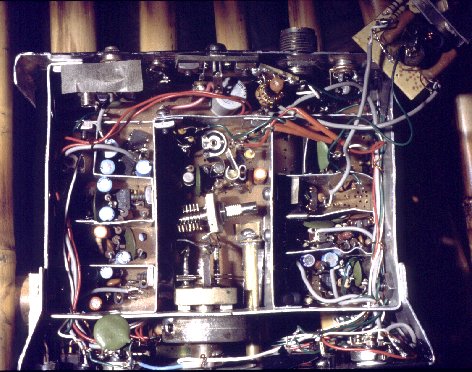
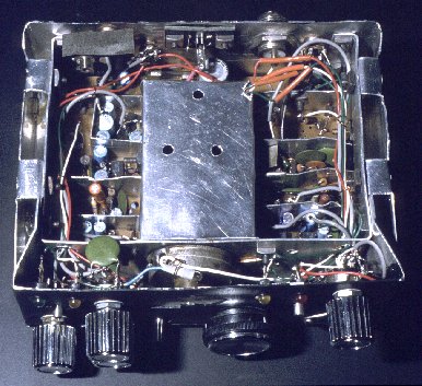 Here is the inside
of the new radio. The transmitter used much the same circuitry as the first
model, but was assembled in a very much more compact way, on a real printed
circuit board! Lots of shielding made it stable. The VFO was now a much
more stable Colpitts type, and thanks to a reduction dial mechanism it
didn't need a separate fine-tuning knob like its predecessor! The receiver
was totally new, based on "An optimized QRP transceiver" by Roy Lewallen,
W7EL, published in the August 1980 QST magazine, but modified for my purposes.
I had four stages of active audio filtering for good selectivity! The TX-RX
switching was fully electronic now, I just did not like relays.
Here is the inside
of the new radio. The transmitter used much the same circuitry as the first
model, but was assembled in a very much more compact way, on a real printed
circuit board! Lots of shielding made it stable. The VFO was now a much
more stable Colpitts type, and thanks to a reduction dial mechanism it
didn't need a separate fine-tuning knob like its predecessor! The receiver
was totally new, based on "An optimized QRP transceiver" by Roy Lewallen,
W7EL, published in the August 1980 QST magazine, but modified for my purposes.
I had four stages of active audio filtering for good selectivity! The TX-RX
switching was fully electronic now, I just did not like relays.
 This
radio worked well and was my workhorse for several years. It traveled up
countless hills and some mayor mountains. But on this photo the station
is assembled on the lunch table in the summer cottage. The radio is complete
now, box and all. Just the amplifier is still unboxed.
This
radio worked well and was my workhorse for several years. It traveled up
countless hills and some mayor mountains. But on this photo the station
is assembled on the lunch table in the summer cottage. The radio is complete
now, box and all. Just the amplifier is still unboxed.
Note that now I even have a more decent microphone than in the old CB
days! I had some more income now and could afford that luxury!
Yes, the station had to be dismantled and stored away before every meal...
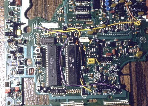 My skills as a
repair man were increasing. Don't you just love this electronic landscape?
I do, I can't help it! This is the CPU section of a Betamax video recorder.
I tracked down a bad solder joint on this board that was causing erratic
operation. I spent two weeks on that. But video equipment was very expensive,
so the owner paid me a tidy sum of money for the fix! To me, as a 15-year-old,
it seemed like a fortune!
My skills as a
repair man were increasing. Don't you just love this electronic landscape?
I do, I can't help it! This is the CPU section of a Betamax video recorder.
I tracked down a bad solder joint on this board that was causing erratic
operation. I spent two weeks on that. But video equipment was very expensive,
so the owner paid me a tidy sum of money for the fix! To me, as a 15-year-old,
it seemed like a fortune!
By the way, do you remember the Betamax format? I used it some time,
in the school's "video academy", to make a movie about Concepcion's tourist
attractions! I remember carrying around lamps that had a total power of
almost 10.000 Watt, otherwise it was just impossible to light the scenes
well enough for those insensitive picture sensor tubes. CCDs were not yet
available. Of course, it was not easy to find enough power outlets for
all those lamps. Today you just need a 30 Watt battery powered light...
Oh oh, I seem to be ooooold!!! :-)
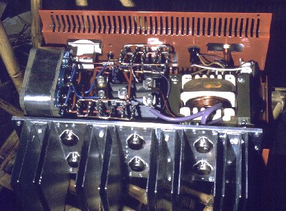
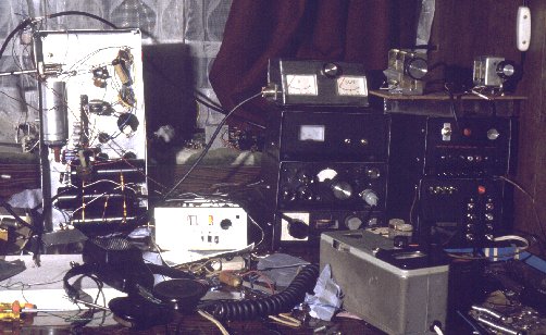 Some
months later. School is a secondary thing in my life, first is ham radio!
The amplifier is now encased in a nice box, sitting on the transceiver
and below the SWR meter. The bright smaller box is a half finished frequency
counter, built from a kit, that has just four digits but counts well into
the UHF range. I regularly used it as a digital dial. Many commercial rigs
still didn't have that feature!
Some
months later. School is a secondary thing in my life, first is ham radio!
The amplifier is now encased in a nice box, sitting on the transceiver
and below the SWR meter. The bright smaller box is a half finished frequency
counter, built from a kit, that has just four digits but counts well into
the UHF range. I regularly used it as a digital dial. Many commercial rigs
still didn't have that feature!
The large open chassis is a tube-type linear amplifier. It started out
with two 2E26 valves, but they were just too small. I soon replaced them
by a pair of 6146Ws. Powered by 1.2 kV, they ran nicely at the 300 Watt
level, driven by the tiny 1 Watt output from my QRP rig!
The greenish gray box in the foreground is a Heathkit grid-dip meter.
CE5DF gave it to me. It's a big help, even today.
Note that poverty had still not left my ham shack. The large power supply
has a gaping hole instead of a meter. Holes are cheaper than meters. Meters
can be added later. And coax connectors were absurdly expensive. I skipped
them and plugged the wires directly into the sockets. See the left side
of the SWR meter...
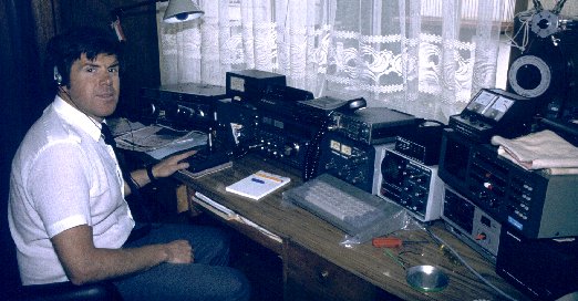
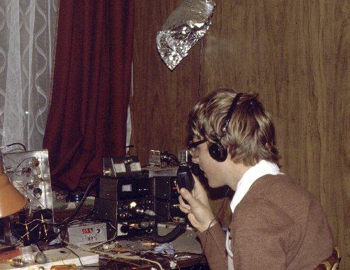 This is a very
rare photo. Indeed it's the only one I have of myself operating my base
station during that era! I always thought, and still think, that I prefer
being the guy BEHIND the camera, not the one IN FRONT of it. It took quite
some stalking efforts to shoot a photo of me! The headphones shielding
off my peripheral hearing helped the sneaky photographer. I still remember
the shock from the photo flash. I thought something in my radio setup had
just exploded!
This is a very
rare photo. Indeed it's the only one I have of myself operating my base
station during that era! I always thought, and still think, that I prefer
being the guy BEHIND the camera, not the one IN FRONT of it. It took quite
some stalking efforts to shoot a photo of me! The headphones shielding
off my peripheral hearing helped the sneaky photographer. I still remember
the shock from the photo flash. I thought something in my radio setup had
just exploded!
The bright thing up on the wall is a lamp screen made from aluminum
foil. There is a 12 V car lamp in it. We had power outages several times
a week, and I had a trusty car battery under the desk...
I was 16 years old, nearly 17.
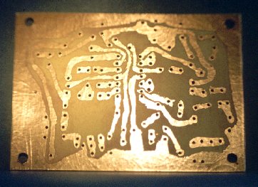 Two years earlier
I had developed a quick way for producing printed circuit boards. I designed
the layout on paper, then taped the paper onto the copper clad board and
drilled the holes through the entire sandwich. Then I removed the paper,
and used fingernail polish to freehandedly draw the copper areas on the
board. Then the board was tossed into acid, and all my shakings got etched,
together with the design, into the copper. The nail polish was removed
using acetone, and the board was ready. The whole process, including design
for a simple board like this, could be done in just over an hour.
Two years earlier
I had developed a quick way for producing printed circuit boards. I designed
the layout on paper, then taped the paper onto the copper clad board and
drilled the holes through the entire sandwich. Then I removed the paper,
and used fingernail polish to freehandedly draw the copper areas on the
board. Then the board was tossed into acid, and all my shakings got etched,
together with the design, into the copper. The nail polish was removed
using acetone, and the board was ready. The whole process, including design
for a simple board like this, could be done in just over an hour.
There was just one problem to this method: I can tell you, it is highly
embarrassing for a 14 year old boy to go into a pharmacy and ask for brightly
colored nail polish!
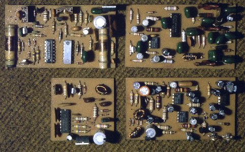 This
is how such boards looked from the component side, after assembly and before
being integrated into radios. These four boards are all the electronics
inside my new creation: A new QRP transceiver! The small board is the VFO,
using a CMOS chip as a buffer. To its right is the receiver board. The
board in the upper right is the transmitter driver, and the upper left
one is the 5 Watt power stage and TX-RX switching logic. Such few components
are needed for a fully functional double side band radio! Just add a box,
a speaker, some connectors, switches, potentiometers, a variable capacitor,
and a few dozen wires.
This
is how such boards looked from the component side, after assembly and before
being integrated into radios. These four boards are all the electronics
inside my new creation: A new QRP transceiver! The small board is the VFO,
using a CMOS chip as a buffer. To its right is the receiver board. The
board in the upper right is the transmitter driver, and the upper left
one is the 5 Watt power stage and TX-RX switching logic. Such few components
are needed for a fully functional double side band radio! Just add a box,
a speaker, some connectors, switches, potentiometers, a variable capacitor,
and a few dozen wires.
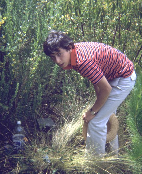
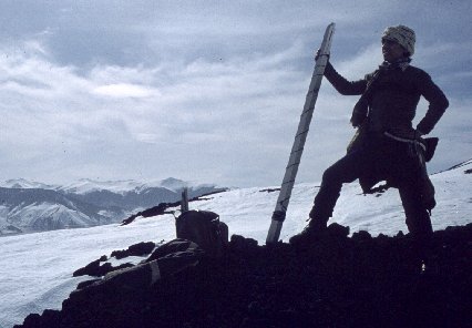 For someone who
likes mountain climbing, and likes radio, what can be better than joining
both? Sebastian Oehrens was my willing helper on an exhausting trip up
the Antuco volcano. We set up my station on the rim of the crater, about
2800 meters above sea level. There are no trees up there, so we had to
carry a foldable mast up the volcano.
For someone who
likes mountain climbing, and likes radio, what can be better than joining
both? Sebastian Oehrens was my willing helper on an exhausting trip up
the Antuco volcano. We set up my station on the rim of the crater, about
2800 meters above sea level. There are no trees up there, so we had to
carry a foldable mast up the volcano.
Sebastian was quite interested in ham radio, but as far as I know he
never got his license. It seems that the stupid requirement for Morse code
knowledge kept him out.
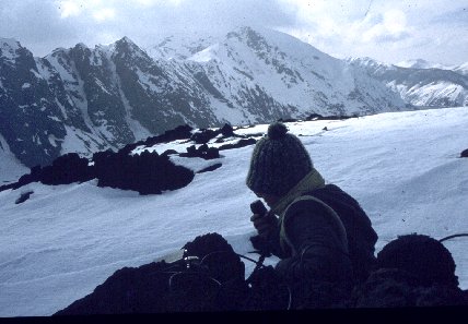 This is me again,
but you cannot see much... I'm wrapped up like on a polar tour. It gets
cold up there, when the sun is blocked and the wind howls. You can see
part of the radio, my new 5 Watt 40 meter rig. It put S9+30dB signals into
locations 800 km away, and nobody wanted to believe that I was running
that low power! I can assure you that a good altitude helps on HF too,
and the snowy reflector did the rest. It was truly enjoyable, despite the
icicles growing on my nose.
This is me again,
but you cannot see much... I'm wrapped up like on a polar tour. It gets
cold up there, when the sun is blocked and the wind howls. You can see
part of the radio, my new 5 Watt 40 meter rig. It put S9+30dB signals into
locations 800 km away, and nobody wanted to believe that I was running
that low power! I can assure you that a good altitude helps on HF too,
and the snowy reflector did the rest. It was truly enjoyable, despite the
icicles growing on my nose.
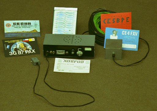
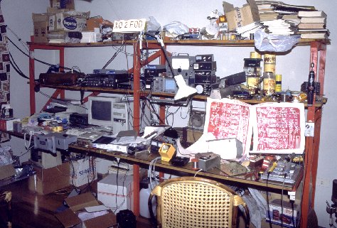
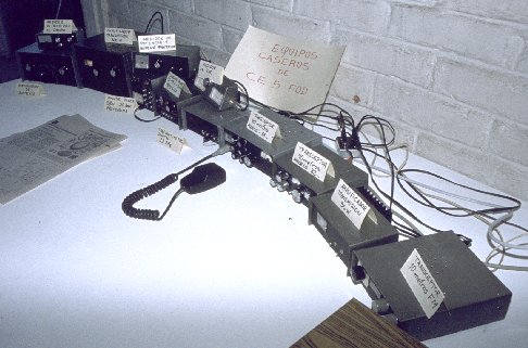 Welcome to the
full line! This was my home built equipment in september 1983, the year
I finished school. I was 17 years old. This photo was shot on a hobby exhibition,
which explains the signs... The entire setup was fully functional.
Welcome to the
full line! This was my home built equipment in september 1983, the year
I finished school. I was 17 years old. This photo was shot on a hobby exhibition,
which explains the signs... The entire setup was fully functional.
From left to right: The new antenna tuner, using a big roller coil.
On top of it sits a small tunable field strength meter. Then comes the
300 Watt amplifier, now boxed too. Then the 15 A power supply, which now
even has a meter closing the hole! On it an RF power meter with built-in
dummy load. Then comes the variable 3 A power supply, and the frequency
counter, now encased in a decent box too. On top of the two is the SWR
meter, almost falling down. Then, the new QRP transceiver! Next to it,
the old one. You can see the similarities. The receivers and oscillators
are pretty much alike, but the new one has an improved transmitter, and
the frequency offset in CW mode is now controllable. It has RIT, too. Then
comes the 30 Watt amplifier, nicely cased, and the former CB transceiver,
which had been converted to 10 meter FM!
Can you understand how I felt explaining all this to the crowds? Almost
like I feel now, bragging about it...!
By the way, the newspaper that's in front of the power supplies features
an article by me, describing the construction of a simple radio, plans
and all, and encouraging kids to join this hobby. By that time I wrote
a lot for magazines and other media.
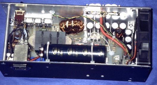
 One day CE5SG
asked if I could build him a good power supply. He had burned out just
too many of those flimsy commercial things. He wanted something that could
deliver full current, as long as he needed it, to power large VHF amplifiers.
I made him buy a huge heavy-duty battery charger, modified the transformer,
used the same case, rectifier, meter, circuit breaker, but added a large
filter and the regulating circuit, using six high-power transistors on
a hefty heat sink. Full protection against both overcurrent and overvoltage
was included.
One day CE5SG
asked if I could build him a good power supply. He had burned out just
too many of those flimsy commercial things. He wanted something that could
deliver full current, as long as he needed it, to power large VHF amplifiers.
I made him buy a huge heavy-duty battery charger, modified the transformer,
used the same case, rectifier, meter, circuit breaker, but added a large
filter and the regulating circuit, using six high-power transistors on
a hefty heat sink. Full protection against both overcurrent and overvoltage
was included.
The last time I asked him about it, he was still using this power supply.
That was 10 years later.
 This guy is the
one. Claudio Santander, CE5SG. The owner of the antenna array at the top
of this page. And the proud owner of the first large "FODelectronic" power
supply, and of some more equipment... He is well known among DXers.
This guy is the
one. Claudio Santander, CE5SG. The owner of the antenna array at the top
of this page. And the proud owner of the first large "FODelectronic" power
supply, and of some more equipment... He is well known among DXers.
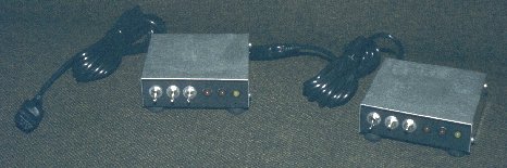 But commercial
production of equipment was just starting. These twins are multistandard
radio modems. The Atari 800XL had become the most common home computer
in Chile, and many hams were using the HAMSOFT program together with some
lousy interfaces. I designed this modem for the Atari to cover the entire
range of frequency pairs, splits and speeds that were used in that time
on ham bands. It was a tiny but capable box. A matrix system programmed
the tone generator, PLL and filter chips.
But commercial
production of equipment was just starting. These twins are multistandard
radio modems. The Atari 800XL had become the most common home computer
in Chile, and many hams were using the HAMSOFT program together with some
lousy interfaces. I designed this modem for the Atari to cover the entire
range of frequency pairs, splits and speeds that were used in that time
on ham bands. It was a tiny but capable box. A matrix system programmed
the tone generator, PLL and filter chips.
I started assembling these modems for sale, but very soon the requests
overwhelmed my production capability. I was now an university student,
and my free time was just too limited. Soon I offered only the kits, so
everyone had to assemble his own modem. Some did, but others didn't. Finally
I gave the business over to XQ5BIB. He cared for the kits, and paid a guy
some money to assemble units for those people who preferred it that way.
He sold the production, and paid me royalties for the design.
We sold these things right into the starting era of packet radio, when
they became obsolete. We even exported them!
 Have a good look
at this picture. It's this radio's last one. The new transceiver was reliable,
and was performing better than this one. I was in real need for components
to put into my new projects, and very short of money. It almost broke my
heart, but I had to disassemble this cute radio, to reuse the parts.
Have a good look
at this picture. It's this radio's last one. The new transceiver was reliable,
and was performing better than this one. I was in real need for components
to put into my new projects, and very short of money. It almost broke my
heart, but I had to disassemble this cute radio, to reuse the parts.
 A last look into
it, VFO shield cover removed. Considering my age when I built it, you will
have to agree that it was well engineered... Of course, it had not been
exempt from problems. The board hanging from those cables is an additional
buffer stage, which proved necessary after the first few contacts, to keep
the balanced mixer from frequency-pulling the VFO. It all was dismantled
that very same day, after these photos were made.
A last look into
it, VFO shield cover removed. Considering my age when I built it, you will
have to agree that it was well engineered... Of course, it had not been
exempt from problems. The board hanging from those cables is an additional
buffer stage, which proved necessary after the first few contacts, to keep
the balanced mixer from frequency-pulling the VFO. It all was dismantled
that very same day, after these photos were made.
 And the bottom
side, under the PCB. As you can see, I had already applied surface-mount
technology! :-)
And the bottom
side, under the PCB. As you can see, I had already applied surface-mount
technology! :-)
I always regretted having disassembled this radio. It was so nice, so
compact... Everything was hand made, there was not a single right angle
in it... I felt like a murderer after destroying it. But, I needed the
parts...
I also shot an "after" photo, showing the heap of recovered components
on one side, and the pile of box parts, shields, and the PCB on the other.
But it broke my heart when I saw the photo today. I will not publish that
one.
 The king is dead.
Long live the king! This was my next radio! It is shown here among some
QSL cards worked with it. Note the special callsigns on the two left cards!
This radio netted me a lot of great contacts! Note also my own QSL card
in front of the radio: I had become XQ5FOD! The change in callsign
prefix is due to the change in license class: I had earned the Superior
license, of which less than 30 existed in the country. It required a Morse
test at 20 words per minute, and proving exceptional participation in ham
radio, among other things. But the reason why I had to wait so long to
apply for that license class was that it required being 21 years old. As
with all previous licenses, I applied for it as soon as I reached the required
age.
The king is dead.
Long live the king! This was my next radio! It is shown here among some
QSL cards worked with it. Note the special callsigns on the two left cards!
This radio netted me a lot of great contacts! Note also my own QSL card
in front of the radio: I had become XQ5FOD! The change in callsign
prefix is due to the change in license class: I had earned the Superior
license, of which less than 30 existed in the country. It required a Morse
test at 20 words per minute, and proving exceptional participation in ham
radio, among other things. But the reason why I had to wait so long to
apply for that license class was that it required being 21 years old. As
with all previous licenses, I applied for it as soon as I reached the required
age.
This photo was made for a magazine article, a considerable time after
I built that radio. It shows the complete portable station. A small battery
case, a mini solar panel for recharging it, and a coiled dipole antenna
with 10 meters RG174 miniature cable. Some green nylon rope included, the
entire communication package weighs in at less than 2kg! The radio measures
20 x 10 x 4.5 cm. Note the tiny microphone. You don't need a big case for
an electret capsule and a microswitch! I took this station along on many
mountaineering trips.
About the internals: I turned away from direct conversion radios. This
transceiver is an up-converting superheterodyne, using a crystal lattice
filter to produce real single sideband signals. It was designed for good
performance, very low power consumption, and easy use. It features wide
range automatic gain control, automatic TX level control, a speech processor,
TX audio spectrum shaping (this increases the perceived signal strength
at the other end by an impressive amount!), a very stable VFO, signal,
power and voltage metering, SWR protection, and a few other goodies. It
is designed for a nominal power supply voltage of 12 V instead of the typical
13.8 V. This allows to use normal 12 V batteries until they are really
empty. The radio works correctly from about 9.5 to 15 V. Current drain
is only 28 mA during receive at moderate volume with the dial and meter
lamps switched off, and on TX it takes an idle current of 70 mA with peaks
of up to slightly below 1 A, while putting 5 W into the antenna. That's
quite a good efficiency.
This radio uses a minimal amount of stages, and most of them operate
at high impedance, to conserve power. There is a MOSFET mixer at the front
of the receiver, then comes an IC IF amplifier, a MOSFET product detector,
and an IC audio power amplifier. Add the AGC circuits, and that's the receiver.
Not a single part could be deleted. The VFO runs at 2.5 to 2.8 MHz, and
is a highly stable Colpitts with temperature compensation. A single FET
is used as buffer. The beat oscillator uses a FET and a crystal. The signal
from the electret microphone is passively coupled into an IC doubly balanced
mixer, the DSB output goes to the crystal filter and the IF amplifier,
which are shared by the receiver. Then follows another IC mixer, and just
two stages of RF amplification using rather hot transistors, together having
a gain of almost 40 dB! The emitter current of the class-A driver is used
to bias the class-B output stage, to conserve power. All control and switching
is done by CMOS circuitry.
I designed this thing during a family summer trip into Chile's beautiful
deep south. The VFO part was designed on Chiloe Island, the IF and receiver
circuit took shape at Futaleufu, Rio Cisnes, Puerto Aysen and Coyhaique,
while the difficult RF power amplifier work was done on the return trip
via Bariloche in Argentina. So this is an international design! Once
back at home, for the first time in my life I did a thorough computer simulation
of the whole thing. I hacked around the program for two weeks, and then
my poor Atari had to spend another two weeks crunching numbers. It found
some potential problems. I improved gain distribution, corrected mistakes,
and then went straight to designing the printed circuit board, without
doing any real-world test.
I had better technology now, using rub-on pads and self-adhesive tapes
on transparent plastic film, then photographically transferring it onto
the board. I made a double sided board, all signal connections on the bottom,
while the top layer was left intact as a ground plane. All ground connections
were soldered from the top side. A single PCB was used to mount everything,
including connectors, switches, the meter, the volume control, even the
dial reduction mechanism was integrated into the PCB design! Then I assembled
the radio, switched it on and started using it. There was no single modification
to do! This was the first time in my life that I designed something as
complex, built it, and had absolutely no trouble with it!
When I applied for my present job, which also was my first "official"
one, I took along this radio. There were two electronic engineers in the
interview room. They asked for permission to open it. I gave them permission.
They removed the screws, looked inside, asked some questions, I answered
them. I got the job.
I still use this radio sometimes. Now it's about 13 years old. It never
developed any problem.
Many times I have been offered heavy money for it. Sorry, it's not for
sale...
 But before I got
that job, and while I was still a university student, my interest ranged
widely into microprocessors. I wrote communication programs for the Atari
and a complete stand-alone RTTY BBS program, both in pure assembler language.
The Atari had no UART usable for these purposes, so each bit had to be
generated in software. Not an easy task, considering that the main CPU
in that computer was shut down 60 times a second, in order to let the graphic
chip access the main memory! Of course, you could disable these interrupts,
but then you got a black screen...
But before I got
that job, and while I was still a university student, my interest ranged
widely into microprocessors. I wrote communication programs for the Atari
and a complete stand-alone RTTY BBS program, both in pure assembler language.
The Atari had no UART usable for these purposes, so each bit had to be
generated in software. Not an easy task, considering that the main CPU
in that computer was shut down 60 times a second, in order to let the graphic
chip access the main memory! Of course, you could disable these interrupts,
but then you got a black screen...
I also wrote several electronic design programs, for active filters,
impedance matching networks, crystal filters, and so on. The circuits were
presented on screen, in text mode, using a modified character set to draw
electronic symbols.
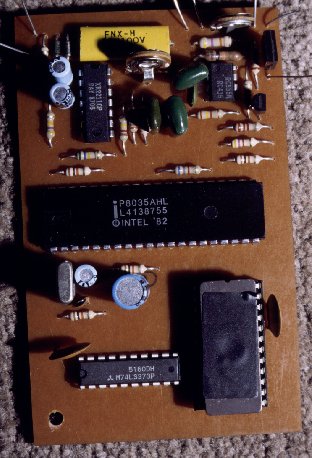
The photo here shows something different. It's a repeater controller.
Based on an 8035 microcontroller, it implements all the basic control,
timers, CW ID, telemetry, and remote control using a proprietary highly
secure code over a low speed subaudible FSK channel. The whole thing runs
from 5 Volt and needs less than 30 mA.
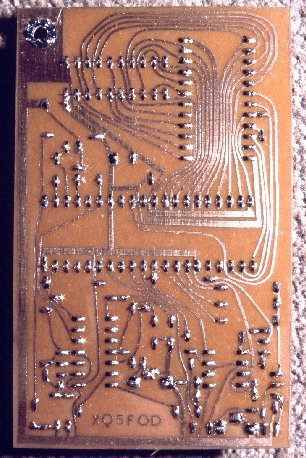 This is the underside.
This was one of the last printed circuit boards I made by rubbing symbols
onto transparent laminate, applying self-adhesive strips, and then doing
the photoetching process. All my later PCBs were done by computer layout,
but the photographic part stays the same until today. I just have not found
any really usable method that can replace it.
This is the underside.
This was one of the last printed circuit boards I made by rubbing symbols
onto transparent laminate, applying self-adhesive strips, and then doing
the photoetching process. All my later PCBs were done by computer layout,
but the photographic part stays the same until today. I just have not found
any really usable method that can replace it.
Note that this is a single-sided board, and it holds the entire circuit
(lots of address and data lines) without needing even a single jumper!
As a well known inventor liked to say, engineering is a combination of
brains and material. The more brains you use, the less material you need.
Even for rather simple projects, as this one.
When the time came for my thesis project at the university, I had so
much to draw upon that I let the professors choose... At the end I wrote
a book about this thing, including all paraphernalia around it: There was
an Atari-based EPROM programmer, together with its control program written
in 6502 assembler, the remote control code generator with its compiled
BASIC program, and of course the controller proper, with its MCS-48 assembler
firmware. Also included was the MCS-48 development platform, hardware and
software including a cross-assembler, which I had made for the trusty Atari!
I remember the professors' puzzled looks when the controller sent its
Morse telemetry. They just had to trust me, as they didn't know Morse code...!
I got the maximum grade.
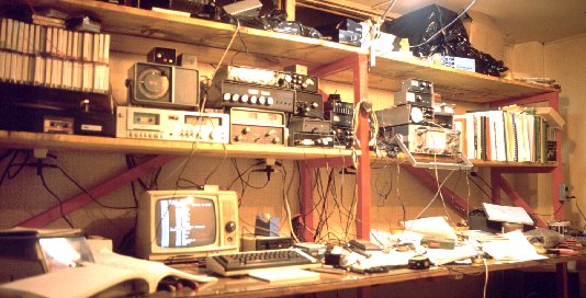 When
I finished university, and took up my new (and first "official") job starting
1989, I had to leave my parent's home, as the job was more than 1000 km
away... I rented a small two-room house in La Serena, and one of the first
things I did there was setting up half of the house as a real radio shack.
I built this large table, which at last could hold everything related to
radio at one place. The music equipment was there too. Note the Atari computer,
using one of those ubiquitous old hybrid (tubes/transistors) TVs as a monitor,
displaying an assembler program. Above are the radios, including a Raytheon
direction finder, music equipment, and to the right is the workshop section.
Note the new equipment: A hi-fi tuner (the shiny thing on top of the music
amplifier), a 60 Watt VHF brick amplifier (top unit just left of the red
riser) which I used with my first factory made radio, a second-hand Kenwood
TR2400! To the right you see an oscilloscope, which I bought cheaply, in
bad condition, and repaired, and above it, believe it or not, is a homemade
portable oscilloscope which I built just two months before I got the chance
to buy the other one! It helps to have two of them... Oh, and the small
thing with the green and red LEDs on top of the direction finder dial is
the UPS used for the Atari computer! Small and effective, like most things
I build! :-)
When
I finished university, and took up my new (and first "official") job starting
1989, I had to leave my parent's home, as the job was more than 1000 km
away... I rented a small two-room house in La Serena, and one of the first
things I did there was setting up half of the house as a real radio shack.
I built this large table, which at last could hold everything related to
radio at one place. The music equipment was there too. Note the Atari computer,
using one of those ubiquitous old hybrid (tubes/transistors) TVs as a monitor,
displaying an assembler program. Above are the radios, including a Raytheon
direction finder, music equipment, and to the right is the workshop section.
Note the new equipment: A hi-fi tuner (the shiny thing on top of the music
amplifier), a 60 Watt VHF brick amplifier (top unit just left of the red
riser) which I used with my first factory made radio, a second-hand Kenwood
TR2400! To the right you see an oscilloscope, which I bought cheaply, in
bad condition, and repaired, and above it, believe it or not, is a homemade
portable oscilloscope which I built just two months before I got the chance
to buy the other one! It helps to have two of them... Oh, and the small
thing with the green and red LEDs on top of the direction finder dial is
the UPS used for the Atari computer! Small and effective, like most things
I build! :-)
The new zone brought with it a change in my callsign: I was now XQ2FOD.
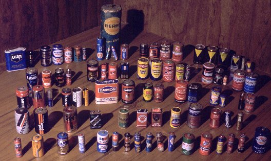 But the small
size of my new house was a real shame. I just had not enough space to take
with me all those things! Among the many beloved objects that had to be
thrown away, or donated to a new loving home, was my battery collection.
Since I was small, I kept all exhausted batteries that were of different
brands or types. This is just a small sample of the treasure in zinc and
carbon that had to be fed to the trash can! There were so many funny things,
like the original and famous "BEREC" batteries, and their cheap and bad
"BEREO" copies! The colors and shapes had all been copied! For several
other brands I had look-alike copies too! For "Eveready" batteries alone
there were three different copy brands! And one of the greatest mysteries
in my life is the gold-and-green "Superpila". It had no other markings,
and was the most humble specimen you can imagine, just a zinc cell in a
carton sleeve! Where was that thing made?
But the small
size of my new house was a real shame. I just had not enough space to take
with me all those things! Among the many beloved objects that had to be
thrown away, or donated to a new loving home, was my battery collection.
Since I was small, I kept all exhausted batteries that were of different
brands or types. This is just a small sample of the treasure in zinc and
carbon that had to be fed to the trash can! There were so many funny things,
like the original and famous "BEREC" batteries, and their cheap and bad
"BEREO" copies! The colors and shapes had all been copied! For several
other brands I had look-alike copies too! For "Eveready" batteries alone
there were three different copy brands! And one of the greatest mysteries
in my life is the gold-and-green "Superpila". It had no other markings,
and was the most humble specimen you can imagine, just a zinc cell in a
carton sleeve! Where was that thing made?
UPDATE: Marco Cutrone contacted me and told that the "Superpila" was an Italian
product, made in Florence. But the factory exists no more.
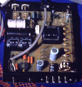 After the hi-fi
tuner I devoted my free time to more serious projects, like this. It's
a 13.8V switching power supply, that can deliver 20 A on an intermittent
basis and 10 to 12 A continuously. It measures 16 x 18 x 4.5 cm, and weighs
considerably less than 1 kg. I used this power supply for eight years,
until I replaced it by a larger one.
After the hi-fi
tuner I devoted my free time to more serious projects, like this. It's
a 13.8V switching power supply, that can deliver 20 A on an intermittent
basis and 10 to 12 A continuously. It measures 16 x 18 x 4.5 cm, and weighs
considerably less than 1 kg. I used this power supply for eight years,
until I replaced it by a larger one.
While I had previously published most of my projects in the chilean
RadioAficion magazine, this one was published in Mundo Electronico, which
I hoped would find more readers, being a general electronic magazine. Previously
I had published other things there too, but never got much feedback. I
finally quit sending them articles. I still sometimes contribute to RadioAficion,
though.
 A great amount
of time was devoted to the two local radio clubs. When I moved to La Serena,
I became a member of both of them, the Radio Club La Serena, and the much
older Radio Club Coquimbo. I'm still a member of the latter, but not of
the former, because I stopped attending when that club devoted its sessions
to fighting each other, until it broke in two. By the way, I also still
am a member of the Radio Club Concepcion, as they named me honorary member
for special merits...! I visit Concepcion once or twice a year, and the
visit to the club is a pleasure.
A great amount
of time was devoted to the two local radio clubs. When I moved to La Serena,
I became a member of both of them, the Radio Club La Serena, and the much
older Radio Club Coquimbo. I'm still a member of the latter, but not of
the former, because I stopped attending when that club devoted its sessions
to fighting each other, until it broke in two. By the way, I also still
am a member of the Radio Club Concepcion, as they named me honorary member
for special merits...! I visit Concepcion once or twice a year, and the
visit to the club is a pleasure.
This photo shows one of the two VHF repeaters the Radio Club Coquimbo
had when I became a member (now it has three). It's installed at the very
top of the Tamaya mountain, overlooking the land and the ocean from its
1280 meter altitude (plus 20 meter of tower!). It's not at all unusual
to contact peruvian stations through this repeater, over a distance of
close to 2000 km. The repeater sits right inside the duct that forms stably
during most of summer!
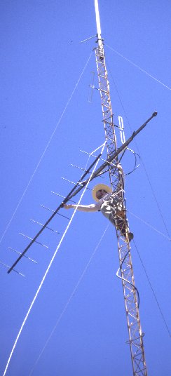 This repeater
was soon enhanced with one of my 8035 controllers, and shortly later a
packet node was added, sharing the tower, cabinet and solar power system.
Here you can see me installing one of the antennas for the node. It was
mounted well below the Phelps-Dodge antenna at the top, to reduce chances
for intermodulation problems. No, that's NOT a mexican hat! It's the somewhat
smaller chilean version! Big enough to throw some shade, but not enough
to get airborne in that mountaintop wind.
This repeater
was soon enhanced with one of my 8035 controllers, and shortly later a
packet node was added, sharing the tower, cabinet and solar power system.
Here you can see me installing one of the antennas for the node. It was
mounted well below the Phelps-Dodge antenna at the top, to reduce chances
for intermodulation problems. No, that's NOT a mexican hat! It's the somewhat
smaller chilean version! Big enough to throw some shade, but not enough
to get airborne in that mountaintop wind.
While the repeater is an old RPTelectronics transmitter with a modern
Hamtronics receiver and my homemade controller, the packet node uses a
very, very old General Electric "Royal Professional" transceiver. It's
built SO solidly that we almost were unable to carry it up the mountain!
I'm still in doubt if those copper moldings are lead-filled...! The
TNC is a PacComm Micropower-2, with THENET firmware. The node has worked
well during the last 9 years, and links packet stations up to 300 km away.
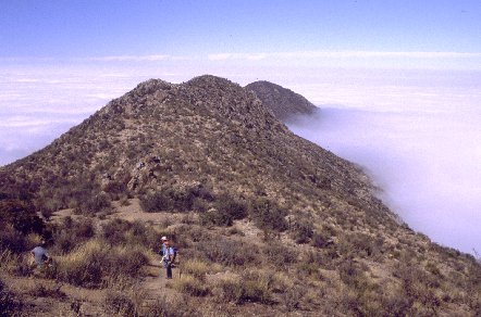 Despite the often-cloudy
weather, solar power provides great performance here, because the mountain
top most often is above the clouds. But of course, there is no road up
to this place! Access needs one hour highway driving from Coquimbo, followed
by half an hour on a maze of dirt roads, then stone-hopping up the trail
in the jeep as far as it will go, followed by a hike through the cloud
cover that can take anywhere from one and a half to three hours, depending
on physical condition and the amount of cargo. Any mission to this place
takes a full day. We try to keep the things reliable enough so we don't
have to come up more than once a year or so. A homemade solar charge regulator
considerably increased battery life, so at least that most heavy work of
all, hauling new batteries up to the summit, has to be done only every
five to six years.
Despite the often-cloudy
weather, solar power provides great performance here, because the mountain
top most often is above the clouds. But of course, there is no road up
to this place! Access needs one hour highway driving from Coquimbo, followed
by half an hour on a maze of dirt roads, then stone-hopping up the trail
in the jeep as far as it will go, followed by a hike through the cloud
cover that can take anywhere from one and a half to three hours, depending
on physical condition and the amount of cargo. Any mission to this place
takes a full day. We try to keep the things reliable enough so we don't
have to come up more than once a year or so. A homemade solar charge regulator
considerably increased battery life, so at least that most heavy work of
all, hauling new batteries up to the summit, has to be done only every
five to six years.
The other two repeaters of our Radio Club are reachable by car, so their
maintenance requires much less effort.
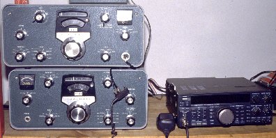 Having a decent
salary now, the era of factory-made radios was starting for me. I had gotten
a tube-type Heatkit RX-TX combo from a work mate, but soon after that I
bought a brand new Kenwood TS450. I later took the Heathkit to my dormitory
at the job (it's remotely located), where I still have it. The TS450 was
first used for a mix of fixed and mobile work. Shortly later I installed
a packet BBS, and since then the radio works 24 hours a day in heavy-duty
forwarding service, without mercy. It has never had a single failure. Well
done, Kenwood!
Having a decent
salary now, the era of factory-made radios was starting for me. I had gotten
a tube-type Heatkit RX-TX combo from a work mate, but soon after that I
bought a brand new Kenwood TS450. I later took the Heathkit to my dormitory
at the job (it's remotely located), where I still have it. The TS450 was
first used for a mix of fixed and mobile work. Shortly later I installed
a packet BBS, and since then the radio works 24 hours a day in heavy-duty
forwarding service, without mercy. It has never had a single failure. Well
done, Kenwood!
As a long-time user of homemade radios, I would like to say that factory-made
radios are better than what you can reasonably build at home. But home
building has still a large appeal, for several reasons: It's fun, it's
highly instructive, but above all, you can tailor the product to your own
very specific need! There just is no factory-made portable 40 meter QRP
transceiver that could outperform mine, in terms of size, weight, power
consumption, and performance!
 In January 1991
I bought my own apartment and gave up that tiny rented house. The radio
desk was disassembled and reassembled in the new home. The station was
growing fast: When this photo was taken, a PC had replaced the old Atari,
complete with flight simulator yoke and pedals... I was flying just in
theory back then! The most important addition to the station was a Yaesu
FT736 satellite transceiver. I had to order it from the USA, because there
was no way to get one locally. In an effort that spanned several years,
I set up a fully automatic groundstation for the digital satellites, complete
with a satellite node and a satgate, coupled to my packet BBS. At the time
of writing this (1999), the satellites are still my primary operating activity
in ham radio.
In January 1991
I bought my own apartment and gave up that tiny rented house. The radio
desk was disassembled and reassembled in the new home. The station was
growing fast: When this photo was taken, a PC had replaced the old Atari,
complete with flight simulator yoke and pedals... I was flying just in
theory back then! The most important addition to the station was a Yaesu
FT736 satellite transceiver. I had to order it from the USA, because there
was no way to get one locally. In an effort that spanned several years,
I set up a fully automatic groundstation for the digital satellites, complete
with a satellite node and a satgate, coupled to my packet BBS. At the time
of writing this (1999), the satellites are still my primary operating activity
in ham radio.
 This is the typical
display on my computer screen. The background window contains the F6FBB
BBS software, the upper window runs SatSked and SatLink together with a
lot of glue-and-fill programs, while the lower one runs FodTrack, my homemade
satellite tracking system (software and hardware) that is now well known
among satellite users worldwide. Several other complementary programs run
in background, and pop up if needed. Thanks to a lot of effort invested
in reliability, I can let this station run for long time without any attention.
I have been away from home for six weeks at a stretch without the station
developing any problem, while most other amateur satellite setups have
a much shorter failure interval. Specially when using Windows, computer
crashes and hangs seem unavoidable. This system, based on DOS and DESQview,
is reliable.
This is the typical
display on my computer screen. The background window contains the F6FBB
BBS software, the upper window runs SatSked and SatLink together with a
lot of glue-and-fill programs, while the lower one runs FodTrack, my homemade
satellite tracking system (software and hardware) that is now well known
among satellite users worldwide. Several other complementary programs run
in background, and pop up if needed. Thanks to a lot of effort invested
in reliability, I can let this station run for long time without any attention.
I have been away from home for six weeks at a stretch without the station
developing any problem, while most other amateur satellite setups have
a much shorter failure interval. Specially when using Windows, computer
crashes and hangs seem unavoidable. This system, based on DOS and DESQview,
is reliable.
Since this photo was made, in 1995, the versions of the programs have
changed, but the basic setup is still the same.
 I have been slowing
down in equipment building, basically because of my increasing involvement
in other hobbies, like making excessively long web pages. But I still enjoy
building equipment from time to time. This is a switching power supply
that delivers 13.8 Volt at 40 Ampere continuous duty. It has high efficiency,
is very reliable, short-circuit protected, and generates absolutely no
detectable radio noise from 100 kHz up. I designed and built it in 1997,
and it was published by ARRL both in
the Radio Amateur's Handbook, and in two parts in the QST magazine, in
the december 1998 and january 1999 issues. Check it out in the homo ludens
electronicus section.
I have been slowing
down in equipment building, basically because of my increasing involvement
in other hobbies, like making excessively long web pages. But I still enjoy
building equipment from time to time. This is a switching power supply
that delivers 13.8 Volt at 40 Ampere continuous duty. It has high efficiency,
is very reliable, short-circuit protected, and generates absolutely no
detectable radio noise from 100 kHz up. I designed and built it in 1997,
and it was published by ARRL both in
the Radio Amateur's Handbook, and in two parts in the QST magazine, in
the december 1998 and january 1999 issues. Check it out in the homo ludens
electronicus section.
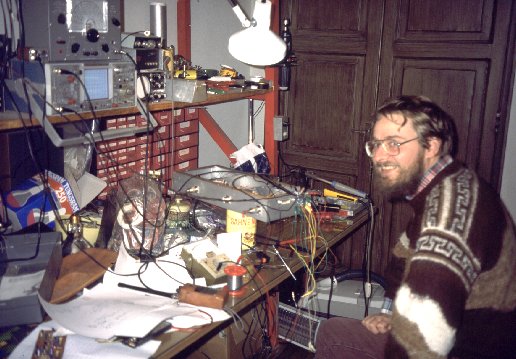 How do I look now? Well, a little
more hair in the face, less on top of my head, all the rest stays pretty much
the same. As you can see, I keep the same working style, which is, fill up the
desk and then work on the lap. The half ready project in this photo is an
inter-repeater link. Completely remote-controlled, it can link its local host
repeater to any, several or all of three neighboring repeaters. It plugs into a
25 pin repeater bus which I designed, that allows to daisy-chain several such
boxes, adding links, telemetry, and lots of other options to any of the club's
repeaters.
How do I look now? Well, a little
more hair in the face, less on top of my head, all the rest stays pretty much
the same. As you can see, I keep the same working style, which is, fill up the
desk and then work on the lap. The half ready project in this photo is an
inter-repeater link. Completely remote-controlled, it can link its local host
repeater to any, several or all of three neighboring repeaters. It plugs into a
25 pin repeater bus which I designed, that allows to daisy-chain several such
boxes, adding links, telemetry, and lots of other options to any of the club's
repeaters.
In 2007 I quit my job and moved to a new QTH at a forest mountaintop, in the
middle of nothing. Any ham will be able to understand my motivations: The
nearest neighbor is one kilometer away, the nearest power line too. That means
zero manmade noise!
The zone change brought along yet another change in my callsign: I'm now
XQ6FOD. But the workbench remains the same, and the mess on it is pretty much
the same too! The satellite station and packet BBS have been shut down, though,
because of the gradual death of Pacsats and the whole Amateur digital
network. My operating has reverted mostly to HF SSB, with some assorted
digimodes thrown in for spice.
I will stop it here. Congratulations for having read up to the end!
You are probably as tired from it, as I am from writing!
Back to the homo ludens radiactivus. And if
you are interested in building equipment, be sure to check the homo ludens
electronicus page.