 When VHF FM
became commonplace among Chilean hams in the 1970s, a considerable
number of repeater stations were set up. Most of these used
either RPT Electronics equipment, or the VHF Engineering
repeater, along with Wacom duplexers.
When VHF FM
became commonplace among Chilean hams in the 1970s, a considerable
number of repeater stations were set up. Most of these used
either RPT Electronics equipment, or the VHF Engineering
repeater, along with Wacom duplexers. When VHF FM
became commonplace among Chilean hams in the 1970s, a considerable
number of repeater stations were set up. Most of these used
either RPT Electronics equipment, or the VHF Engineering
repeater, along with Wacom duplexers.
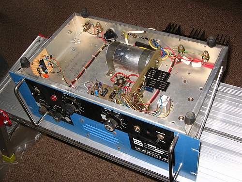
The VHF Engineering repeater, pictured here upside down, came from the factory with a CW identifier, which was programmed by soldering a lot of diodes in a matrix to form the station's callsign. Back in its day, it certainly fullfilled its purpose. But nowadays many hams don't know Morse code, enforcement officers know it even less, and so CW identifiers have become a beeping nuisance rather than a useful device. The CW identifier of these repeaters is configured in such a way that when the time for identifying comes, it will happily transmit the ID on top of any station using the repeater at that moment! That's pretty rude, I would say...
Several hams have told me that they can't leave their radios on a repeater frequency, because while their wifes would tolerate the occasional call or conversation, a sudden tirade of high pitched Morse beeping was definitely beyond their tolerance level! That's why repeaters set up later, such as in the 1990s, often used voice identifiers.
Except for their beeping nuisance, the old VHF Engineering repeaters still work pretty well, and so I was asked by Radio Club Temuco to upgrade them to voice ID. I designed a little voice ID module that is a direct drop-in replacement for the original VHF Engineering CWID module. It uses the ISD1740 voice recorder chip, in a very simple circuit. It can record an ID message more than 30 seconds long, which is far more than required. And it is a polite identifier: When time for identifying comes, it patiently waits for the repeater's user to stop transmitting, and only then it transmits its ID.
While I designed this module specifically for the VHF
Engineering repeater, it can be used in many other repeaters with few
or perhaps no modifications.
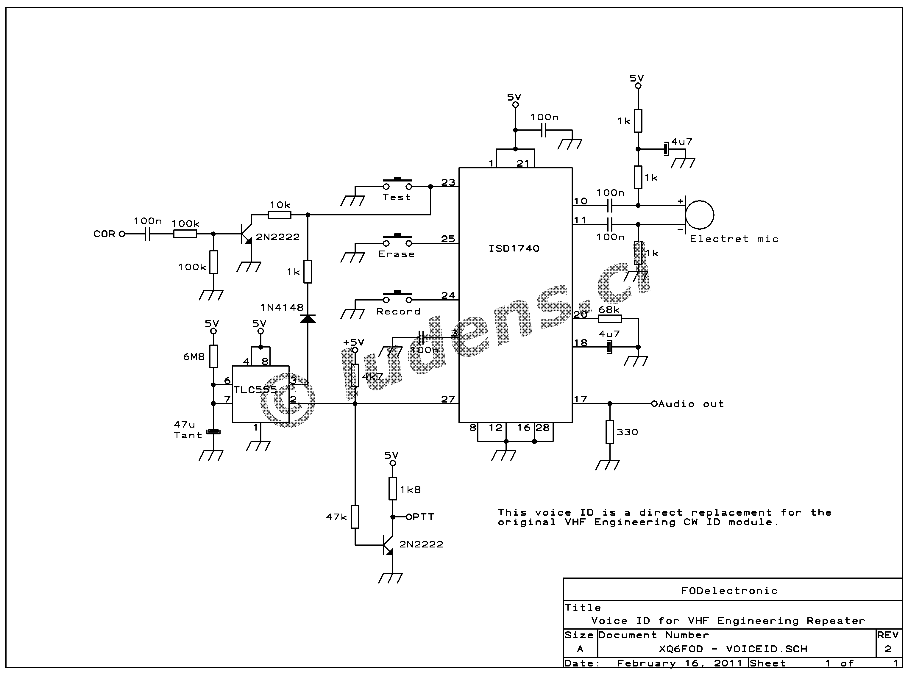 You
can click on the schematic diagram to get a high resolution version,
which will be fine for printing.
You
can click on the schematic diagram to get a high resolution version,
which will be fine for printing.
The ISD1740 is used as a down-to-basics pushbutton-controlled recorder, fitted with its own electret microphone, and a timer was added to set the ID interval. Two transistors provide the inverting interfaces needed to connect this circuit to the VHF Engineering repeater.
I did not include a potentiometer for setting the output level, as the repeater has more than enough level setting pots. If you want to include one, it's easy to do so. Just place it over the 330 Ohm resistor. Any value from 1k to 10k should be fine.
There is a small amount of DC on the output. In applications where this is troublesome, add a coupling capacitor.
The TLC555 timer IC used here is a CMOS replacement for the ubiquitous NE555. Don't use the NE555, because it might not be able to work with the high impedance timing network required for the ID time. With the values shown here, the ID interval is slightly more than 4 minutes, and it can be lengthened, if desired, by increasing the value of the 6.8 megaohm resistor, or of the 47uF tantalum capacitor. You might have success using an aluminium electrolytic capacitor in place of the tantalum, but it depends on how low its leakage is. A tantalum cap is a safer bet.
This circuit will play the ID when the COR input goes high, if the ID interval has elapsed. While it plays, the PTT output is high. The COR module of the repeater takes care of sending the COR signal, and tying the ID module's PTT output into the TX control and tail circuits.
To record an ID message, first the ERASE button is pressed, to delete the existing ID message, if any, and then the RECORD button is pressed and held while speaking the message into the microphone. To test the message, without waiting for the ID interval to complete, the repeater is activated and the TEST button is pressed before the repeater drops.
The ISD chip can retain the recorded message for longer than a
repeater's lifetime, so there should be no worry about this.
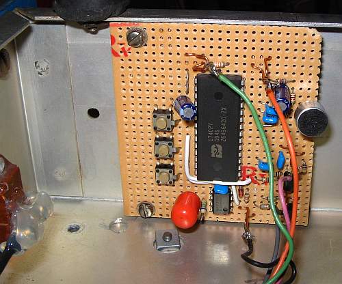 I was too lazy
to design a printed circuit board, so I used a piece of universal board
to assemble it. It's not as beautiful as a true PCB, but works as well.
The board is much smaller than the repeater's original CW identifier,
and uses two of the original four mounting posts. It uses the same
connecting wires. So it's really a drop-in replacement.
I was too lazy
to design a printed circuit board, so I used a piece of universal board
to assemble it. It's not as beautiful as a true PCB, but works as well.
The board is much smaller than the repeater's original CW identifier,
and uses two of the original four mounting posts. It uses the same
connecting wires. So it's really a drop-in replacement.
The repeater has its AC power switch, with exposed connections, located very close to the ID board (left edge of this photo). To keep any button-pressing fingers from accidentally drawing some undue current from the power switch, I coated the exposed connections with hot melt glue. There are too few hams left, so we shouldn't electrocute any...
Back to the homo
ludens electronicus
page.