Wideband SWR meter
Everyone involved with radio transmitters needs some instruments to assess
basic antenna functionality. Among these instruments, the best-known and
most-used one is the Standing Wave Ratio meter. Some radio amateurs develop
a cult for these little gadgets, having them in line all the time and watching
the needles bounce while they chat. I have seen some guys owning 5 or 6
SWR meters, and no other instrument relating to antenna testing! While
it's unfortunate that some people - specially amateurs - assign so much
importance to SWR and so little to other parameters, it's also a fact that
SWR needs to be known, so if you use transmitters, you need an SWR meter.
What is SWR?
Transmission lines have a certain characteristic impedance, typically 50
or 75 Ohm for coaxial cable, and about 300 to 450 Ohm for open-wire balanced
feedline. Such an impedance stating means that the cable is naturally suited
to carry a ratio of voltage to current according to this impedance - for
example, a 50 Ohm coaxial cable should carry 1A for every 50V applied to
it, and the phase of voltage and current should be the same. Only in these
conditions will the cable transfer the most power while loosing the least,
and more importantly, only if this ratio is adhered too, the ratio will
stay the same along the cable! That means, if to a 50 Ohm cable you connect
a load (antenna) with a different impedance, then the cable will transform
this impedance, so that at the input to the cable you will have an impedance
that is neither the load impedance nor the cable impedance!
It's outside the scope of this article to explain in full the impedance
transformations along transmission lines. You can look that up in many
electronics textbooks. For now, let's go back to the theme of SWR! The
fact is that the impedance transformations along a transmission line lead
to sections with higher and lower voltage, and higher and lower current,
called standing waves because the highs and lows are spaced in wavelengths
at the operating frequency, and do not move along the cable. The voltage
standing wave ratio is simply the ratio between the voltage at the
highest and lowest point of such a standing wave! This ratio happens to
be equal to the ratio between the highest and lowest current, and also
is equal to the ratio between the cable impedance and the load impedance!
Which means that it is also equal to the ratio by which the current-to-voltage
ratio departs from the correct value it should have for that cable!
Examples always help to clear up misconceptions. So here goes an example:
Let's say that you connect 10 meters of 50 Ohm coaxial cable to an antenna
that is perfectly resonant on 146 MHz , but has a feed resistance of only
25 Ohm. This will be an SWR of 2:1, because the antenna will be taking
2 A for each 50V applied to it, twice as much as the cable likes. The cable
will transform this impedance along its length: A quarter wave away from
the antenna the impedance will be 100 Ohm! Another quarter wave further,
it's back to 25 Ohm. This cycle repeats: Every half wave from the antenna,
the impedance will be 25 Ohm, in the midpoints between them it will be
100 Ohm. At all other points along the cable, the impedance will be reactive,
even if the antenna is perfectly resonant and thus has no reactance! And
now, the most confusing statement for novices: Even while the impedance
varies through a large range along the cable, the SWR along it stays totally
constant at 2:1! If you don't believe this, you have several choices:
Try it, or study it in a book, or think about it, or close your eyes to
the fact if you prefer; but the fact will not change!
In practice, a lossy coaxial cable will tend to make SWR lower
as you get away from the antenna, but you need really lossy cable to notice
this, and you should not use such bad cable!
Instead of this approach, you can also think of SWR in another way:
Imagine the transmitter sending a wave up the cable, in the proper voltage
to current ratio. This will be a traveling wave. Now, the load will reflect
a portion of this wave if it is not of the same impedance as the cable.
This reflected wave will travel back to the transmitter, creating interference
patterns along the cable, resulting in the standing wave of voltage and
current maxima and minima. While one wave travels up and the other travels
down the cable, the interference patterns stay fixed. This is just another
way to look at exactly the same phenomenon.
Common SWR meter topologies
It's easy enough to go into a radio store and buy one. You can get them
in a wide variety of sizes, shapes, power ratings, frequency ranges, in
analog and in digital versions, with a single meter, with two meters, with
a crossed-needles meter, and I would not be surprised if you even could
choose the color! But there is one department in which almost every factory-made
SWR meter falls short: Frequency coverage. Many SWR meters are limited
to just the HF range, just VHF, and often they are accurate only over an
even smaller range.
This limitation comes from the technology they use. There are a few
circuit topologies in common use. One is the toroid bridge. This is basically
a design in which a sample of the antenna line current is taken via a toroidal
transformer, and a sample of the voltage is taken by a capacitive divider.
The two samples (both converted to small RF voltages) are combined in proper
phase relation and amplitude using a bridge circuit, and then rectified,
the result being two DC voltages proportional to the amplitudes of direct
and reflected waves on the transmission line.
This approach works well over a moderate frequency range, and even permits
accurate power measurements over such a range, but at very low frequencies
the current sample gets too influenced by the magnetizing current of the
transformer, and the capacitive divider rises too much in impedance, so
that both sample voltages become inaccurate. On the high frequency side
of the range, the inter-turn capacity of the transformer plays a large
role, and the capacitive divider affects the measured impedance of the
transmission line, again making measurements imprecise. This circuit can
be used easily over a frequency range of 1:10, and some manufacturers push
it as far as 1:100 (160 m to 2m is common), but this compromises accuracy
on both sides.
The other very common commercial SWR meter topology is the Monimatch.
It is harder to understand for newcomers, as it is a transmission-line
design employing distributed coupling between the coax line and one or
two sensing wires. It is extremely simple in design, but needs to be properly
built to work well, and it has a very large disadvantage: Its sensitivity
varies hugely with frequency! Such a SWR meter, designed for HF, may require
much more than 100W to take a reading at 160 meters, and may be burned
out by a similar power on 10 meters! If you try to use it at VHF, even
1W may drive it crazy, and you will not get an accurate SWR reading.
The XQ2FOD SWR meter
I went back to the very basics, making an SWR meter that someone surely
has built at least 100 years ago, but I have never seen it used in any
commercial or homemade gear. It is a simple resistive bridge. It works
perfectly well over a very wide frequency range, is highly accurate over
it, and is very simple and cheap to build. Are you interested? If so, then
I have to tell you about the disadvantages too: It can only digest low
power. A half Watt is more than enough for good measurements at any frequency,
and up to 2W is OK. Above this, it will start smoking! So, if you want
to measure SWR using your 100W transceiver, you had better remember turning
the power down before connecting the meter. Of course, measuring SWR of
antennas at low power means much reduced chance of creating interference
to others! It also means eliminating any risk of burning up the transmitter
by measuring an unknown load with very high SWR - more so as the resistive
loading provided by this meter will guarantee that your transmitter never
sees more than 2:1 SWR, regardless of what you do at the meter's output!
This meter is designed as a test instrument, to be connected, used for
taking the necessary readings, and then disconnected. It makes no sense
to leave it in the line permanently, like some people do, because it eats
up 3/4 of the transmitted power, and a similar part of a received signal.
 Here
is the schematic of the SWR meter, exactly as I published it in the Chilean
magazine Radioafición. You can also get a high resolution version
for printing purposes by clicking on the image. I hope the few Spanish
words will not upset you too much. I was too lazy to edit them...
Here
is the schematic of the SWR meter, exactly as I published it in the Chilean
magazine Radioafición. You can also get a high resolution version
for printing purposes by clicking on the image. I hope the few Spanish
words will not upset you too much. I was too lazy to edit them...
Three pairs of 100 Ohm resistors are combined in a bridge circuit, with
the load as the fourth resistor. D1 rectifies a sample of the input signal,
while D2 rectifies the differential voltage across the bridge, which is
proportional to the square root of reflected power. In this case the two
output voltages are applied to a ganged potentiometer and to two simple
galvanometers, but I have built several other units in which these voltages
are used by digital displays, microprocessors, etc.
Let's do some analysis: At first we will assume a 50 Ohm load is connected
to the antenna side, and a 5Vrms RF signal is applied to the input (this
would be 1/2W across 50 Ohm). At the anode of D1 we would have 2.5Vrms,
or 3.5V peak, which would give 3.5V DC (the voltage drop of the germanium
diode is negligible at the low current involved). D2 would see exactly
the same RF voltage at both sides, and in the same phases, so it will not
produce any DC output. The forward meter will move (we can set the pot
to place the needle at full scale), while the reflected signal meter will
stay at zero, indicating a 1:1 SWR. The transmitter will see 2 times 100
Ohm in parallel, or 50 Ohm, 1:1 SWR too. One quarter of the power will
be dissipated in each of the resistor pairs, while the remaining quarter
gets delivered to the antenna.
Now let's go to one extreme: Disconnect the load! We all know that this
is infinite SWR. D1 would still see half of the input voltage, and as there
is now no current in R1/R2, and no voltage drop across them, D2 sees "the
other half" of the input voltage, and thus produces the same rectified
output as D1 does. Both meters will deflect by the same amount, indicating
that all power is being reflected, and the SWR is infinite. The transmitter
will see 100 Ohm load, a 2:1 SWR, far away from causing danger to any transmitter.
And that is the worst SWR it will ever see through this meter.
Third test: Let's short circuit the output! We know that
this too is infinite SWR. And from the circuit it's clear enough that with
the antenna terminal shorted, both diodes see the same voltage - same deflection
on both meters, infinite SWR, and the transmitter sees 50 Ohm in parallel
with 100 Ohm, which is 33 Ohm, or 1.5:1 SWR.
Let's now run the example posed in the SWR explanation near the top
of this page: A 25 Ohm load. We know this should be 2:1 SWR. D1 will as
always see half the input voltage, while D2 will have half the input voltage
on one side and only one third on the other side. So it sees one sixth
of the input voltage, which is one third as much as D1 sees. When the pot
is adjusted for the forward meter to show full scale, the reflected signal
meter will indicate one third scale, equivalent to one ninth power. At
this point the 2:1 mark must be placed on the meter.
And if the impedance is 100 Ohm? In this case D2 sees two thirds of
the input voltage on one side, still one half at the other. The difference
still is one sixth of the input, still one third of what D1 sees, and the
reflected signal meter will correctly deflect to the 2:1 SWR mark.
What happens if the impedance of the load is 50 Ohm, but with nonzero
phase angle? In that case, both the voltage and the phase of the
RF signal at D2's cathode will deviate. The funny, curious and nice thing
is that whatever values you may try, the resulting rectified DC voltage
is always correct! Try it, if you feel like doing some math! I will limit
myself to showing you an extreme example: Say, you connect a capacitor
that has 50 Ohm reactance (a 470pF one would be close to this at 40 meters).
We know that a capacitor cannot dissipate power, so the SWR meter had better
show infinite SWR! Let's see:
The compounded impedance of our 470pF "antenna" and R1/R2 is 70.7 Ohm,
45 degrees. The current through them will thus be 0.0707A, phase-advanced
by 45 degrees. Then the voltage across the capacitor will be 3.53V, phase-lagging
by 45 degrees. As the voltage at D2's anode is still 2.5V at phase zero,
the angular compounding produces another 2.5 V across D2, phase-lagging
by 90 degrees. The phase information gets lost in the rectification, but
the 2.5 Vrms magnitude is the same seen by D1, thus the two DC outputs
are equal, indicating infinite SWR. Nice, huh? You can measure reactive
parameters without needing reactive components in the instrument!
Construction
One of the nicest things about this project is that it's easy to build
and requires no calibration. Just be sure to mount the RF-carrying components
with the shortest leads you can, directly on the antenna connector. The
input connector can be farther away, that's not so critical. Place the
100 Ohm resistors physically close to the ground plane, so that the parasitic
capacitance cancels out lead inductance. Do not use single 50 Ohm resistors,
they are too inductive! The ideal is either 2 of 100 Ohm like I did here,
or even 3 units of 150 Ohm each. If you use even more resistors in parallel,
of higher values, the result tends to be somewhat capacitive. The diodes
work at higher impedance, so their leads may be a little longer, and they
should NOT be physically close to the ground! The cabling of the potentiometer
and meters carries DC only and is totally uncritical.
You will need to draw the meter scales. The forward meter should be
marked just with the "set" point near full scale, and if you like it, you
can subdivide it into percentile power markings (remember that power is
proportional to the square of voltage, so 25% power is at mid scale). You
may also calibrate the meter in absolute power for a specific setting of
the potentiometer.
The reflected signal meter is best marked directly in SWR. The infinite
mark goes at the same level where the set point of the forward power meter
is. 3:1 SWR is at 1/2 of that, 2:1 SWR at 1/3, while 1.5:1 SWR goes at
1/5 of the scale. If you want to add marks for the high range too, 5:1
SWR is at 2/3 of the range, and 10:1 is at 82%. If you want additional
markings, it's good to know this equation:
SWR = (1+p) / (1-p) where p is the
position on the meter scale, ranging from 0 to 1.
Performance
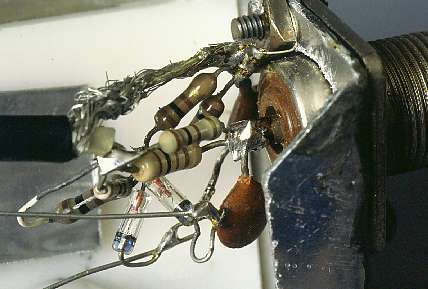 I have build
over 10 versions of this circuit over the years. The original one shown
in the schematic appears on this photo. It uses germanium diodes, half-Watt
carbon film resistors and SO-239 connectors. It works well from the lowest
frequencies I have cared to try it (around 1 MHz), up to 150 Mhz with high
accuracy, and 500 Mhz with degraded accuracy (showing 1.3:1 SWR for a pure
1:1 one).
I have build
over 10 versions of this circuit over the years. The original one shown
in the schematic appears on this photo. It uses germanium diodes, half-Watt
carbon film resistors and SO-239 connectors. It works well from the lowest
frequencies I have cared to try it (around 1 MHz), up to 150 Mhz with high
accuracy, and 500 Mhz with degraded accuracy (showing 1.3:1 SWR for a pure
1:1 one).
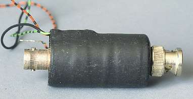 Another
version I built uses 1/4 Watt resistors and Schottky (hot carrier) diodes.
I built it into a copper tube of 20 mm, with one BNC connector on each
end, bringing out the DC signal leads. That one works well from the same
low frequency, up to about 1500 MHz, with good performance, and gets kinky
at around 2 GHz.
Another
version I built uses 1/4 Watt resistors and Schottky (hot carrier) diodes.
I built it into a copper tube of 20 mm, with one BNC connector on each
end, bringing out the DC signal leads. That one works well from the same
low frequency, up to about 1500 MHz, with good performance, and gets kinky
at around 2 GHz.
 Some time
ago, I got a Digital SWR meter, an Daiwa DP-830, very cheaply. That meter
has two independent sensors: One is a current sensor/voltage divider circuit
which is rated for HF and up to 150MHz at high power. It uses SO-239 connectors
and works very well at HF, but on the 2 meter band it is not very accurate.
Some time
ago, I got a Digital SWR meter, an Daiwa DP-830, very cheaply. That meter
has two independent sensors: One is a current sensor/voltage divider circuit
which is rated for HF and up to 150MHz at high power. It uses SO-239 connectors
and works very well at HF, but on the 2 meter band it is not very accurate.
The second sensor is a monimatch, rated for 2 meters through 70 centimeters,
using N-type connectors. It's quite usable as an SWR meter, even if not
laboratory grade, but the power measurement is nonsensical with this sensor.
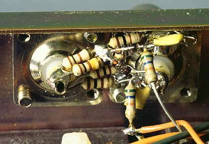
So I decided to add a third sensor, for low power work over the entire
spectrum. I used BNC connectors, in order to have an additional choice
of connectors on the meter... The third sensor was installed on the
back of the instrument, and from the outside looks like it was factory-made.
On the inside it doesn't - but it works very well, providing high accuracy
all the way from 160 meters right through 23 centimeters. This sensor
uses quarter-Watt resistors with minimal lead lengths, tucked close to
the case in order to compensate for the stray inductance by stray capacitance,
and the diodes are HP-2800 Schottky ones. The output resistors were selected
so that the power indication on the digital meter has a fixed, known relationship
to the real power: 1:50. So, for 2 Watt input power the meter reads 100
Watt. That's mighty fine for impressing your buddy with how much power
your handy delivers! :-)
 Just for the fun of it, I put together one using surface mount components
and SMA connectors, with proper care for the impedance of traces. I could
not really find out its upper frequency limit, being short on test equipment,
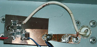
but at least from 1Mhz to 4GHz it worked well! I have no photo of
that one, but here is a photo of a surface mount sensor built by
Alexei. He kindly sent me this photo, which illustrates well how the meter
can be built. Note that all parts carrying RF are assembled close together,
close to the output connector, on a ground plane that helps keep the impedances
down. How high in frequency the meter can work, depends on things like
the board's dielectric constant, the sizes of the parts and the tracks,
and so on. Without caring much for these things, but building the sensor
as compact as shown here, it will work far into the UHF range. With proper
trace impedances, and hot carrier diodes, it should work well into the
SHF range.
Just for the fun of it, I put together one using surface mount components
and SMA connectors, with proper care for the impedance of traces. I could
not really find out its upper frequency limit, being short on test equipment,
but at least from 1Mhz to 4GHz it worked well! I have no photo of
that one, but here is a photo of a surface mount sensor built by
Alexei. He kindly sent me this photo, which illustrates well how the meter
can be built. Note that all parts carrying RF are assembled close together,
close to the output connector, on a ground plane that helps keep the impedances
down. How high in frequency the meter can work, depends on things like
the board's dielectric constant, the sizes of the parts and the tracks,
and so on. Without caring much for these things, but building the sensor
as compact as shown here, it will work far into the UHF range. With proper
trace impedances, and hot carrier diodes, it should work well into the
SHF range.
I don't think you will ever see an SWR meter with this circuit offered
commercially. It has the weakness of blowing up if you accidentally pump
more than a few Watt into it, and manufacturers would probably not trust
their customers to handle the product with care. But a home builder is
much more aware than the average user of what he is doing, so I trust you!
And if you anyway blow it up, at least you can replace the burnt resistors
yourself, and they are really cheap!
Back to the homo ludens electronicus
page.