Improved single-cell LED flashlight
Being a
flashlight builder since age 7, I can't resist the temptation to build
more and more of them, even 50 years later. The technology has changed,
but the fun remains the same. 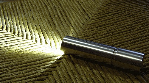 Flashlights
can be large and powerful, or small and convenient to carry. In
the latter category, flashlights using a single cell are very
convenient, due to their size and usage simplicity. In the old times of
incandescent bulbs, all it took was a 1.2V bulb, placing it in a
reflector and wiring it up with a battery, so that flashlight building
was a purely mechanical task. But in 2015 the device of choice is the
LED, due to its far better efficiency and reliability. And since white
LEDs need around 3V to operate, they require electronics to be used
with a single, cheap AA cell.
Flashlights
can be large and powerful, or small and convenient to carry. In
the latter category, flashlights using a single cell are very
convenient, due to their size and usage simplicity. In the old times of
incandescent bulbs, all it took was a 1.2V bulb, placing it in a
reflector and wiring it up with a battery, so that flashlight building
was a purely mechanical task. But in 2015 the device of choice is the
LED, due to its far better efficiency and reliability. And since white
LEDs need around 3V to operate, they require electronics to be used
with a single, cheap AA cell.
I had already built single-cell LED flashlights
before, using several small LEDs in series, but when I stumbled across
half-watt LEDs with built-in lens, it struck me that these are ideally
suited for homebuilt flashlights using a single AA cell. So I set out
to build another nice little lamp.
This one has SMD electronics,
on a tiny printed circuit board, and a machined aluminium body. Instead
of a switch, the rear end is screwed slightly out to turn the lamp off,
by opening the battery contact.
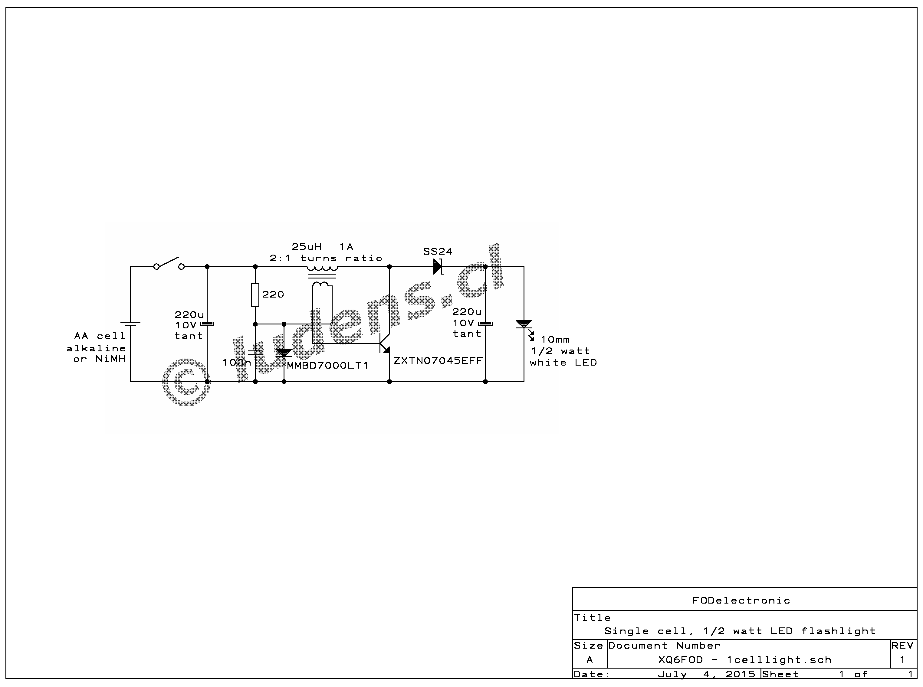
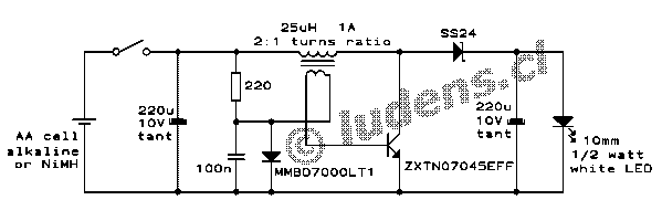 The
circuit is about as simple as it can be: A free-running, self-excited
boost converter, using a low saturation voltage transistor and a
Schottky rectifier, to converter the input voltage to what the LED
needs. This circuit is able to work down to a very low input
voltage, making full use of the battery cell.
The
circuit is about as simple as it can be: A free-running, self-excited
boost converter, using a low saturation voltage transistor and a
Schottky rectifier, to converter the input voltage to what the LED
needs. This circuit is able to work down to a very low input
voltage, making full use of the battery cell.
I used a
factory-made SMD inductor, removed from a junked portable CD player,
along with a few new SMD parts. The inductor got a hand-wound secondary
winding, for the feedback. I adjusted the operating power by
selecting the proper value for the resistor in the circuit, which
controls the transistor's base current, thus defining at what collector
current it will desaturate and thus end the inductor charging in each
cycle.
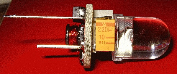 A little round single-sided printed circuit board was made,
which carried all the components, assembled in a very compact way. The
LED, which is a 10mm through-hole type, goes on the non-copper
side, along with the two tantalum capacitors, which make good use of
the space between the board and the LED. All other parts are installed
in normal SMD style on the copper side of the board.
A little round single-sided printed circuit board was made,
which carried all the components, assembled in a very compact way. The
LED, which is a 10mm through-hole type, goes on the non-copper
side, along with the two tantalum capacitors, which make good use of
the space between the board and the LED. All other parts are installed
in normal SMD style on the copper side of the board.
 As you can see, even this small board has a lot of space left, since the circuit is so simple.
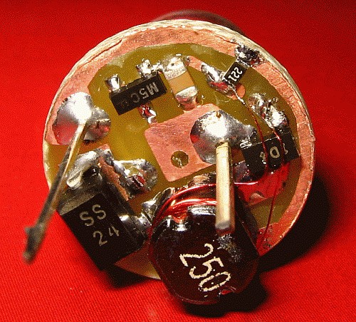
For
the tests I left one LED pin and another piece of wire stick out, to
make convenient connection points for the battery. Later, not shown in
this photo, I clipped the right-side wire and soldered a small brass
cylinder into/onto the center hole, to act as contact point for the
negative battery pole. The wire on the left side, which is the positive
connection, was simply bent to act as a spring and make contact to the
aluminium housing, whose cap connects to the battery's positive side.
That's very crude, but sort of works. Feel free to use a better
arrangement, that doesn't use aluminium as contact material...
 This
shows how small the assembly is. Well, it's a 10mm LED, and the PCB was
made 15mm diameter, the same size to which I turned the inside of the
housing, to fit the AA battery, which may be up to 14.5mm in diameter.
This
shows how small the assembly is. Well, it's a 10mm LED, and the PCB was
made 15mm diameter, the same size to which I turned the inside of the
housing, to fit the AA battery, which may be up to 14.5mm in diameter.
 Playing with the little lamp, before building the housing.
 Here is the PCB layout. You have to scale it so that the outer diameter of the outer copper arc is 15mm.
It's
seen right onto the copper, with no mirroring, so make sure to invert
it (mirror view) if you want to print the image and place it ink-down
onto your sensitized board.
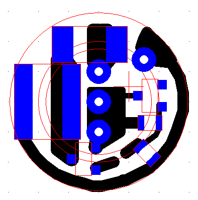 And
this drawing shows how the parts are located on the board. As usual on
my site, you have to work out yourself which part is which.
And
this drawing shows how the parts are located on the board. As usual on
my site, you have to work out yourself which part is which.
Two
holes are for the LED pins. The center hole is to center the negative
connection post, and the last hole has a wire soldered through, that
connects to one of the tantalum caps between the board and the LED, and
has its other end contacting the aluminium housing.
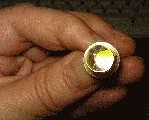
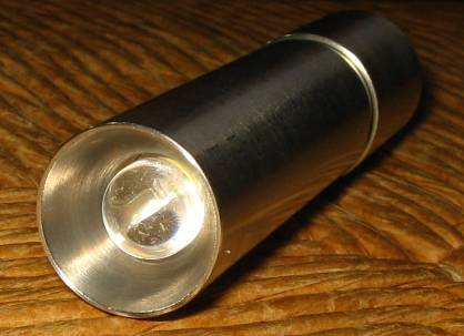 Seen
from the front. I made a reflector-like shape in the aluminium, but
that's really not very important, because most of the light
concentration is done by the LED's built-in lens, which has roughly a
30° opening angle.
Seen
from the front. I made a reflector-like shape in the aluminium, but
that's really not very important, because most of the light
concentration is done by the LED's built-in lens, which has roughly a
30° opening angle.
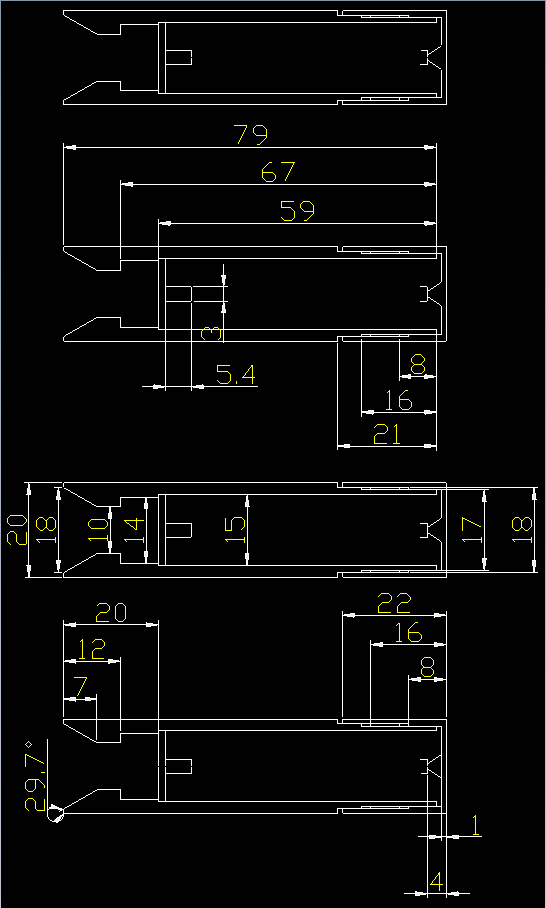
 If
you really want to copy my flashlight's aluminium body, be my guest.
Here is the design, with all dimensions. You can click it to get a
larger version. If you prefer, you can also download the file in DXF format, and open it in the CAD program of your preference.
If
you really want to copy my flashlight's aluminium body, be my guest.
Here is the design, with all dimensions. You can click it to get a
larger version. If you prefer, you can also download the file in DXF format, and open it in the CAD program of your preference.
In
this drawing the electronics are only minimally shown: The PCB, the
negative connection post, and the positive cap of the battery.
The drawing is repeated several times, to accomodate all dimensions without making too much of a mess.
Of course you will need a lathe to make this housing.
Note
that one mechanical piece isn't drawn here: A foam rubber ring that
goes inside the cap, and keeps the battery from rattling around when
the end cap is screwed out a turn or two to keep the lamp off.
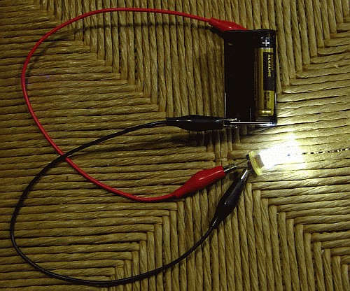
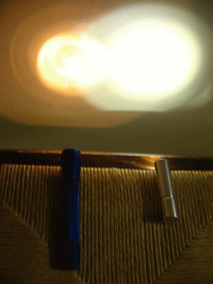 And
here is the shootout! The left lamp is an old-fashioned Mini-Maglite
that uses two AA cells and a tiny incandescent bulb. On the right,
my LED lamp, using a single AA cell. Both lamps have fresh
batteries in them.
And
here is the shootout! The left lamp is an old-fashioned Mini-Maglite
that uses two AA cells and a tiny incandescent bulb. On the right,
my LED lamp, using a single AA cell. Both lamps have fresh
batteries in them.
This circuit runs the LED at roughly
100mA, which should be safe given its 150mA spec. It draws around
250mA, when the battery is at 1.3V. It works fine both with an alkaline
or a rechargeable cell, and should run roughly 7-8 hours on the
alkaline, and slightly less on a rechargeable.
I'm writing this
page roughly 7 years after having built this lamp. The little lamp has
worked well except for occasional contact problems between the positive
contact wire and the aluminium body. Someday I will improve that by
running a soldered metal foil all the way from the PCB to the positive
side of the cell. And it has had one accident: A Duracell leaked, and
made a terrible mess!
It's a very practical flashlight to
carry around for emergencies, because it's small enough to disappear in
a pant pocket, without being felt, and still bright enough to find
one's way in the dark, work in dark places, etc.
Of
course these days everybody runs around carrying a cellphone, and every
cellphone has a flashlight built in... but this little lamp is a lot smaller and lighter than a cellphone!
Back to homo ludens electronicus.