A high power LED flashlight
 Building
flashlights seems to be a fixation of mine. I built my first one at age
5
or so, and now that I'm nearing ten times that age, I'm still building
flashlights. This time the project of choice was a high power LED
flashlight with several interesting features:
Building
flashlights seems to be a fixation of mine. I built my first one at age
5
or so, and now that I'm nearing ten times that age, I'm still building
flashlights. This time the project of choice was a high power LED
flashlight with several interesting features:
- It uses a Cree X-lamp high power LED;
- It drives the LED at two power levels;
- The LED current is regulated;
- It uses rechargeable AA batteries;
- It has a wide beam with very even illumination, ideal as work light,
reading light, or walking light;
- The light color is neutral white, not the bluish color produced by
most
"white" LEDs, nor the yellow/orange glow of incandescent lamps and
"warm white" LEDs;
- It is controlled by a single pushbutton, through an
electronic circuit;
- It fits comfortably in the hand.
At its high power setting it provides slightly over 3 watt,
and
a runtime of 2 hours per charge, while at low power it runs at 0.3
watt,
and can operate for more than 20 hours per charge.
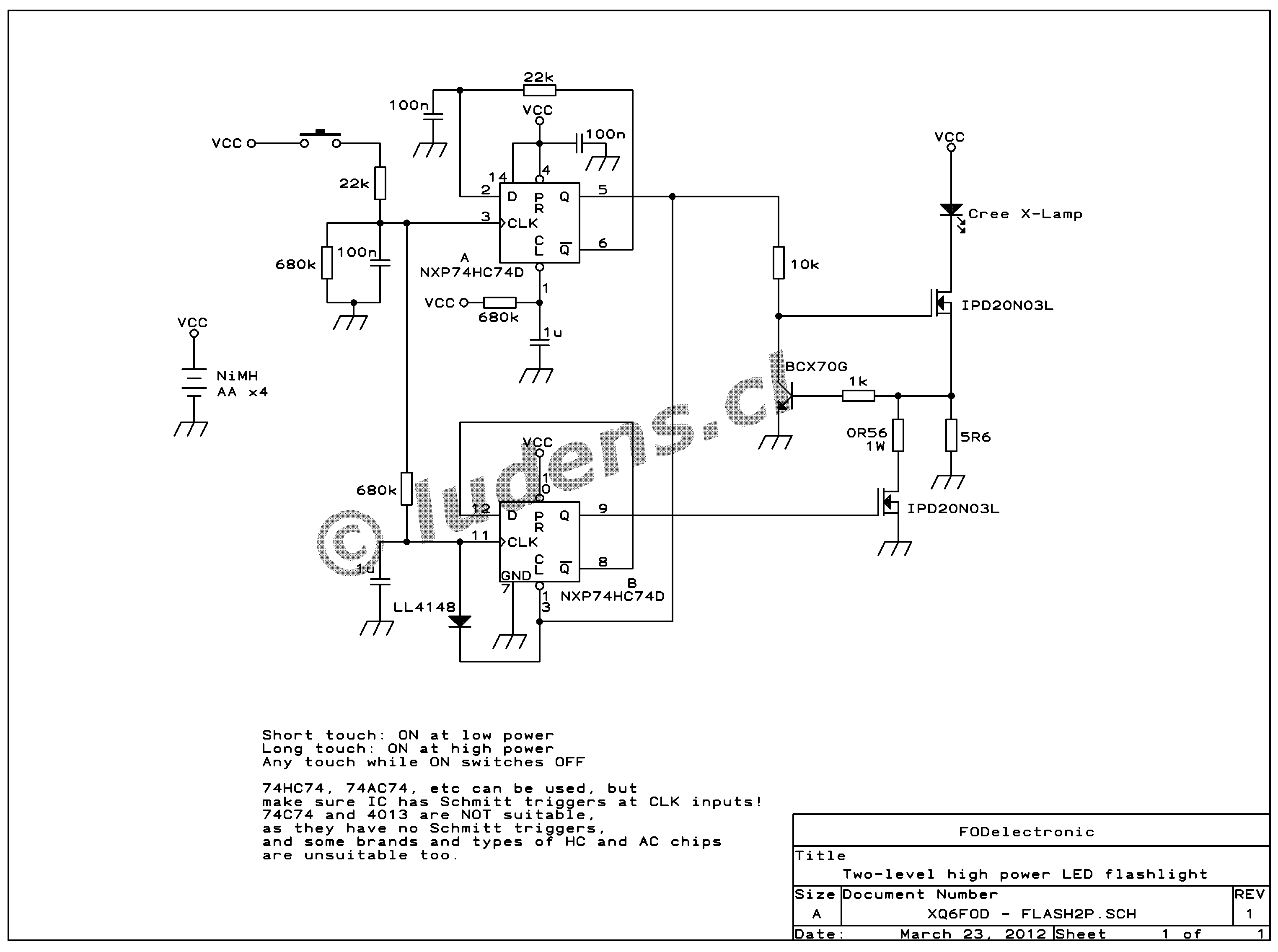
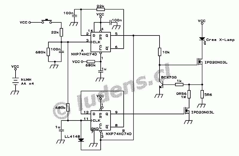 Let's
start with the schematic. The control circuit is permanently
powered by the batteries, but consumes essentially no current while
standing by. It consists of a dual flip-flop IC with some
timing networks wrapped around, driving a current regulator that has
two selectable current levels.
Let's
start with the schematic. The control circuit is permanently
powered by the batteries, but consumes essentially no current while
standing by. It consists of a dual flip-flop IC with some
timing networks wrapped around, driving a current regulator that has
two selectable current levels.
When inserting the batteries, the time delay circuit at pin 1 of the
flip-flop IC first holds down that pin, causing the upper flip-flop to
come up in a defined condition, with pin 5 at logic low. This in turn
applies a "clear" signal to the lower flip-flop, so this one also comes
up
in a defined state. The MOSFETs don't get any bias. The capacitor at
pin 1 soon charges up, and there is no further current drain anywhere
until you press the pushbutton for the first time. The current consumed
by this CMOS IC in static condition is totally negligible.
When the button is pressed, a time delay circuit performs contact
debouncing, and then the upper flip-flop sees an upgoing transition at
its clock input, making it change state. This will apply Vcc to the 10k
resistor biasing the upper MOSFET, which will start conducting. This
MOSFET forms a current regulator, together with the 5.6 Ohm resistor
and the bipolar transistor. The circuit will regulate so that the
bipolar transistor is just biased into conduction, which happens at
roughly 0.56V. Thus the LED current will be regulated to 100mA . The 1k
resistor exists only to protect the bipolar transistor from excessive
base current during transient conditions.
If the pushbutton is realeased sooner than about a half second after
having been pressed, the lamp stays operating in this low power
setting. But if the button is kept depressed, after a bit more than
half a second the voltage at pin 11 will cross the switching threshold.
At that time the lower flip-flop changes state too, switching the lower
MOSFET fully on. This places the combination of the 0.56 Ohm resistor
and the MOSFETs RdsON in parallel with the 5.6 Ohm resistor, resulting
in an effective resistance that makes the current regulator deliver a
pretty precise 1 ampere to the LED.
When the button is released, the CLK inputs eventually return to logic
zero, which has no effect on the flip-flops. But if the button is
pressed while the lamp is on, regardless of whether that happens in
high or low power, it will change the state of the upper flip-flop,
switching the lamp off, and alsoclearing the lower flip-flop, thus
returning the whole circuit to its default condition. The diode
quick-discharges the long time delay capacitor at pin 11, so that the
logic will
operate reliably even if the user fiddles quickly with the button.
Note that this circuit is picky regarding the exact flavor of CMOS
flip-flop chip you use. Most flip-flops require the clock signal to
complete transitioning between logic levels very quickly, and they will
not work in
this circuit, where
the clock signals come from RC time delay circuits and thus
have slow rise times! If you have a
look at 74HC74 data sheets from different manufacturers, you will note
that a few versions have Schmitt triggers built in at the clock inputs,
while most do not have these Schmitt triggers. Only versions that
have these Schmitt triggers are suitable for this circuit! The
NXP74HC74D specified in the diagram is fine.
The time delay circuit between pins 6 and 2 is also involved in
overcoming the trouble caused by the slow clock signal. Some samples of
this circuit worked without this RC delay, but others were picky. With
this delay, they all work fine.
Surely some of my readers would ask why I didn't use a switching
regulator, to improve efficiency. The reason is simple: There isn't
very much to improve! When the batteries are fully charged, they
deliver about 5.0V. The LED needs about 3.2V, the current sensing
resistor needs 0.6V, and the MOSFET also needs some voltage because of
its RdsON. Only about 1V remains to be wasted by a linear regulator,
which is just 20% of evitable loss. And as the batteries run down, this
20% drops, and by the end of the charge, there isn't any surplus
voltage left at all!
A switching regulator needs more complex circuitry, which takes some
power for itself, and it needs an inductor, which has a
significant resistance, which causes additional loss. And it
needs a MOSFET and a current sensing resistor, just like the linear
regulator. So a switching regulator would only be marginally more
efficient than this linear regulator, when the batteries are full, and
it would be LESS efficient than the linear one, when the batteries are
nearing the end of their charge! The net gain in efficiency turns out
so small, that it isn't worth the added complexity of a switching
regulator.
A word about the MOSFETs: These are high current devices with
a
low threshold voltage, which I rescued from an obsolete PC motherboard.
Although they may seem like overkill, the low RdsON that comes with
their high current rating is very important in this circuit!
 The
printed circuit board
The
printed circuit board
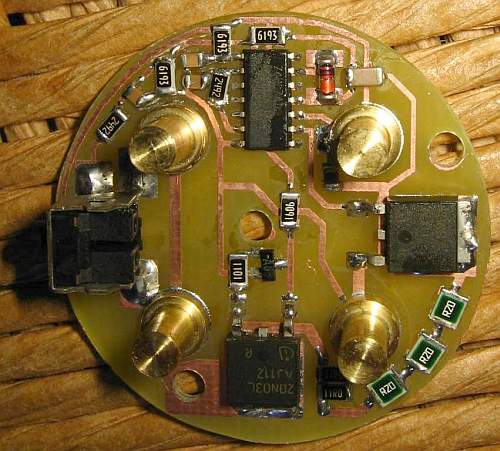
The
circuit was build in surface mount technology, on a round board that
makes use of nearly the full diameter of the lamp, which is dictated by
the dimensions of the AA batteries.
The battery terminals are also integrated on the PCB, eliminating some
wires. The pushbutton I used is really a through-hole device, but I
bent its pins sideward to use it for surface mounting.
The only part that's not mounted on this board is the LED! This is
motivated by the LEDs need for good heatsinking, which is easier to
achieve by mounting it separately.
There are just three holes in the board. Two are for the mounting
screws, one of which also serves to connect to the negative side of the
LED. The center hole gives access to the positive pad of the LED. It is
connected to the board my means of a short wire - the only wire in the
whole lamp!
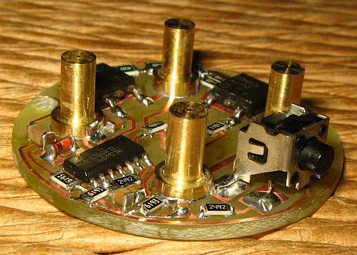
This side view allows to better see the pushbutton, and to note the
height and shape of the battery contacts, which were turned from thin
brass stock on my lathe.
Note that the two chassis pins of the pushbutton, which only serve a
mechanical function, are electrically connected to two battery contacts
which are just an interconnection of two batteries. There is no other
contact from this net into any other part of the circuit, and the only
reason to connect the pushbutton chassis to anything is that this was
simpler than trying to insulate it!
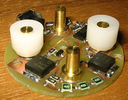
A view from the other side. Note that here the plastic sleeves for two
of the battery terminals have been installed. These sleves go on the
terminals that will connect to the positive poles of two batteries. The
sleeves leave the brass contact slighly recessed, so that if the
batteries were accidentally installed with reversed polarity, the
negative side of the batteries won't make contact, preventing any
damage to the circuit.
Also, when installing the batteries, these big sleeves are an
unequivocal visual guide, telling where the positive poles have to go!
Note that of the two MOSFETs, one has a broad copper path to
the hole that will be connected by a screw to the aluminium
frontal
section of the lamp. This helps provide some heatsinking. This
MOSFET might dissipate up to two watts, if the flashlight is used with
fresh alkaline cells, so it needs some heatsinking, although not much.
The other MOSFET works only in full saturation, so it needs no
heatsink. Note that my design isn't very elegant, in that it uses two
power MOSFETs, when a more intelligent design could have used a single
one for both power levels. This happened because I tried to make the
design simple, and use the components I had on hand. These MOSFETs came
from an
old PC motherboard, so they were free and I could afford to use two!
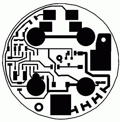
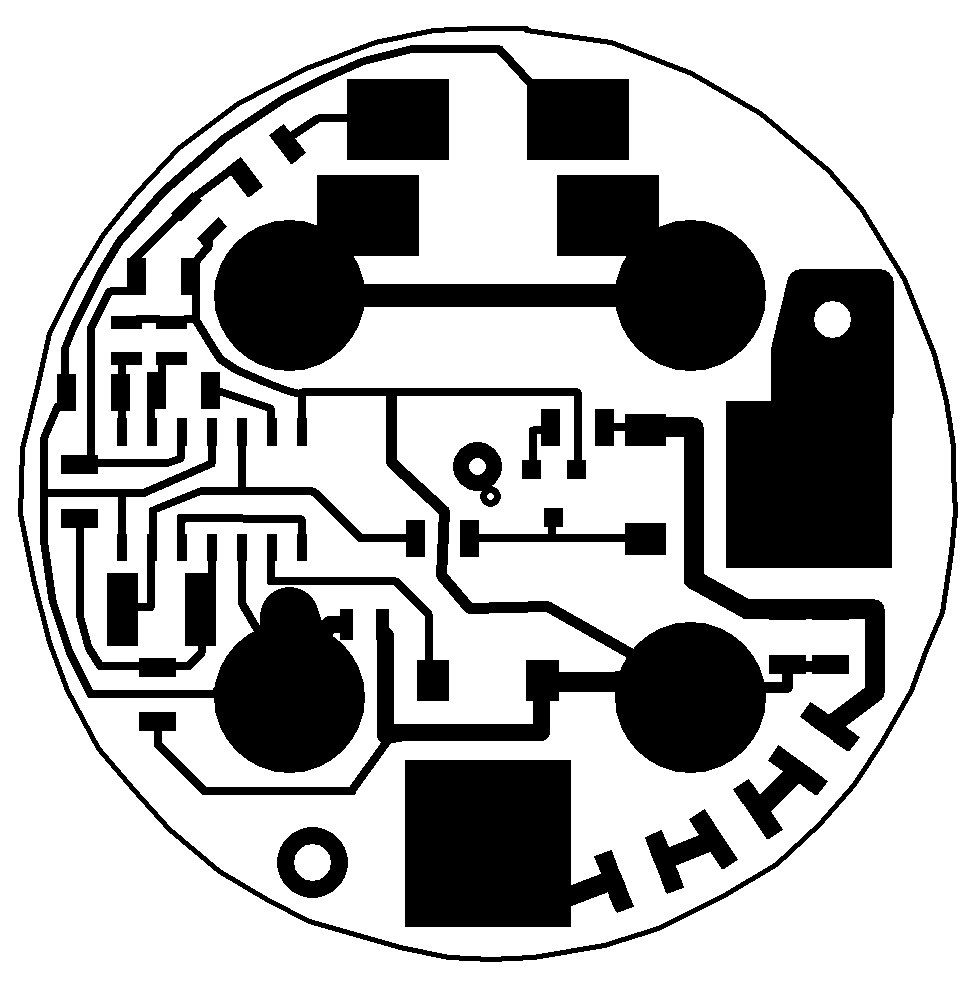
To make the PCB, of course you need its design... Here it
is!
Click on the drawing to get a big copy, which is good enough to print a
positive film transparency for making the PCB. You might have to scale
it.
The diameter of the circle is 38mm.
Note that instead of a single resistor of 0.56 ohm , 1 watt, I used
three smaller ones in series, rated at 0.2 ohm each, and I think a half
watt each. Even a quarter watt would be (barely) enough.
The LED
 The
Cree Xlamp XP-G is a tiny (3.5mm square) but powerful
surface-mount LED. It has three solder pads: Two narrow ones, which are
the electrical contacts, and a big one, which serves just to transfer
heat into the substrate material. Normally these LEDs are soldered to
printed circuit boards made on very thin materials that have high
thermal conductivity. A commonly used material is a thin plastic sheet
sandwiched onto a thick aluminium plate, with copper patterns
deposited on the plastic.
The
Cree Xlamp XP-G is a tiny (3.5mm square) but powerful
surface-mount LED. It has three solder pads: Two narrow ones, which are
the electrical contacts, and a big one, which serves just to transfer
heat into the substrate material. Normally these LEDs are soldered to
printed circuit boards made on very thin materials that have high
thermal conductivity. A commonly used material is a thin plastic sheet
sandwiched onto a thick aluminium plate, with copper patterns
deposited on the plastic.
Another common mounting method is using standard fiberglass printed
circuit board, but selecting very thin board, and placing a lot
of small vias under the LED chip, to conduct the heat through
the
board. Then the board with LED(s) is sandwiched to a heat sink.
Unfortunately it's very hard for a hobbyist to obtain small quantities
of special board materials, or to make very thin metallized holes in
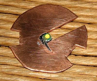
boards. So I came up with a much simpler, coarser, more brutish, but
highly effective way to mount my LED. I cut, hacked, and filed a piece
of 1mm thick copper sheet into the shape you can see here (you will
understand the reason for that shape later), and soldered the LED to
it, in such a way that the negative pad and the thermal pad are
soldered to the copper plate, while the positive terminal is in the
air, and can be soldered to a thin wire. 63/37 solder paste for SMD
work was used, and the plate was simply heated up with a hot air gun,
while using a piece of aluminium scrap to keep the LED from
wicking fully onto the board and soldering all three of its
pads. Due to
the high surface tension of liquid solder, there is a very strong
tendency for parts to float into the center of a pool of liquid solder.
I chose the "neutral white" version of the LED,
which has a
color temperature of roughly 4000 to 4500K. This is a very pleasant
color, very much more so than the cutting cold blueish white of most
"white" LEDs, the horrible reddish orange of glow bulbs, or the
fully fledged yellow of LEDs rated as "warm white".
The lens
Most flashlights concentrate their light into a very narrow beam. This
allows their makers to brag about what a great distance they can cover,
and about the light intensity in the center of the beam.
Sure, but such narrow beamed flashlights are a real pain to use in most
practical situations, when you are not trying to discover an owl
perching on a tree three blocks down the road, but instead you are
trying to change a flat tire in the night. In most practical situations
you want a wide, even flood light, not a narrow spot! So the question
arises whether any sort of beam concentration device is wanted at all.
It turns out that the Cree Xlamp is designed to provide smooth
flooding illumination over a wide angle, and this angle is actually too
wide for practical flashlight use. I have found this ideal beam angle
to be roughly 45 to 60 degrees, while the Xlamp provides more than
twice that. So I designed a lens that takes the light from the Cree LED
and bundles it into this optimal 45 degree beam, providing very even
illumination over that circle. The lens is made from acrylic, so it can
easily be made on a lathe. It's an aspheric design, computed in a very
simple way in a little homemade BASIC program, using nothing more
complicate
than the material's refraction index (1.492), the equation of
refraction (one of the most basic equations in optics), and simple
trigonometry. The image shows a very crude plot of the lense's cross
section. The lens has a diameter of 20mm, and mounts with its flat
surface at 5mm distance from the LED to give the rated beamwidth. It is
possible to change this distance slightly to adjust the beamwidth, but
it should not be overdone, because the shape is optimized for this
distance, and at any other distance the light distribution over the
bright area will not be as even.
Here is a list of coordinates, expressed in millimeters, which you can
use to make this lens. If you have a CNC lathe, its child's play to
make a lens like this. With a conventional, manual lathe (that's my
case), it takes an hour of careful work, followed by some smoothing and
polishing. Note that my BASIC program has a bug, that results
in
the output being a bit wavy. You can see this both in the plot and in
the coordinate list! So feel free to smooth out the coordinates
by hand and eyeball. It's what I did when I made my lens!
Someday
I will debug that program...
Radius
Thickness
10.00
0.00
9.80
0.00
9.81
0.31
9.60
0.30 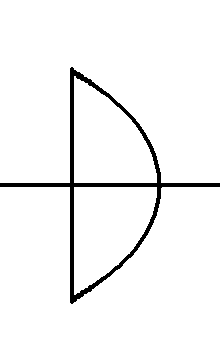
9.61
0.62
9.39
0.60
9.41
0.93
9.19
0.91
9.19
1.25
8.98
1.24
8.97
1.57
8.76
1.58
8.73
1.89
8.54
1.93
8.49
2.21
8.31
2.29
8.23
2.54
8.06
2.66
7.96
2.88
7.80
3.03
7.67
3.23
7.52
3.40
7.37
3.59
7.21
3.77
7.05
3.96
6.88
4.15
6.70
4.34
6.52
4.53
6.33
4.72
6.13
4.91
5.93
5.10
5.71
5.29
5.49
5.47
5.26
5.66
5.02
5.84
4.76
6.02
4.50
6.19
4.23
6.36
3.95
6.53
3.65
6.68
3.35
6.83
3.04
6.97
2.72
7.09
2.39
7.21
2.05
7.31
1.71
7.40
1.36
7.47
1.00
7.53
0.64
7.57
0.28
7.59
0.00
7.60
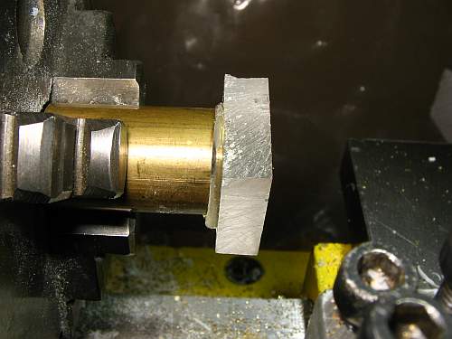
The lens fabrication procedure starts with putting a piece of
brass in the lathe, that should have a diameter just below that of the
finished lens. I used round 3/4 inch stock, which is about 19mm
diameter. Of course, it's easy to take a somewhat larger brass piece,
and turn it down to size.
This brass piece is turned on the front, to give it a flat and
precisely aligned surface. The brass piece should not be removed from
the lathe from now on, until the lens is completely finished, to avoid
alignment problems.
A sufficiently large piece is coarsely cut from a flat sheet of common
clear acrylic, and hot-glued to the brass rod. To do this, the hot melt
glue has to be applied as a thick droplet onto the middle of the
acrylic piece, and then this must be pressed quickly and firmly against
the brass, because the cold and highly heat-conductive brass will make
the hot melt glue set almost instantly. This piece of acrylic must have
at least its rear surface flat and smooth. Otherwise you first have to
polish it.
Then the roughly cut piece is turned into a cylinder of the full lens
diameter. After this, the fun work starts: Taking the calculated list
of coordinates, the lens is slowly carved out, layer by layer, to the
exact calculated coordinates.
This picture shows about one quarter of this work done.
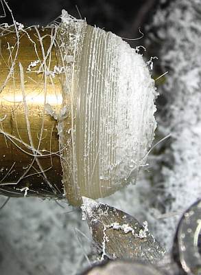
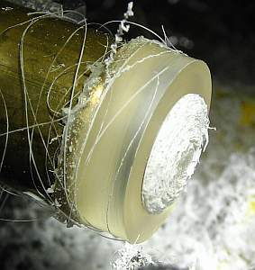
And here the turning work is ready. Of course the lens now has a
staircase approximation to its final shape, and needs to be smoothed.
This is done with sandpaper, starting with a relatively coarse grade to
erase the steps, and then making quick, light passes of all
intermediate sandpaper grits, down to the finest you can get. The lathe
runs, while you play with the sandpaper on the lens. Water lubrication
is needed, so you need wettable sandpaper. The first, harder work
of erasing the step marks is done with a hard backing behind the
sandpaper, while for the successive steps a soft backing (your finger)
is better.
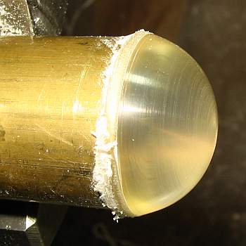
That will leave you with a lens looking like this. Note that the
streaks and spots that show up on its surface are not really on the
lens! These are features of the brass surface behind it, which wasn't
polished! Due to refraction in the lens, they look like they were on
the lens surface.
The lens is finished by giving it a few passes with polishing compound,
first using medium grade, then fine grade.
To remove the lens from the brass rod, simply heat up the brass, which
melts the glue and releases the lens. The glue residue easily wipes off
from the acrylic, by using your fingers as tools.
 The
body
The
body
I made the body of my flashlight on my lathe, too. I mean, if I have a
lathe, I have to use it, right?
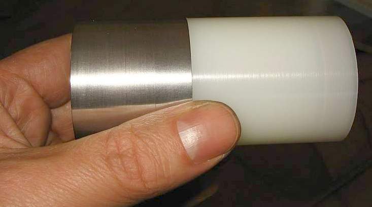
The front section was made from aluminium, because I need a thermally
conductive material there, to serve as a heatsink for the LED. The rear
section instead was made from plastic, which is lighter, and also is
easier to work with. This is important when drilling the four holes for
the batteries!
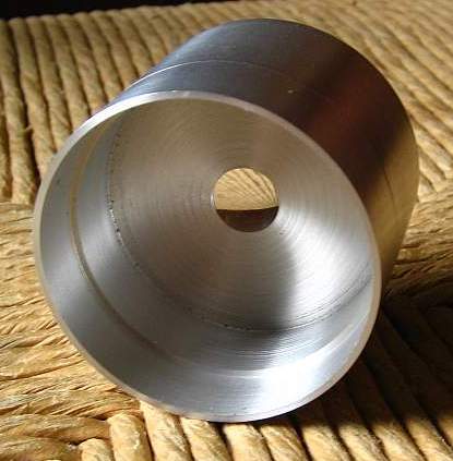
Basically this front piece is a section of tube, with a thick wall
roughly in the middle. This wall has a small conical reflector around
the LED, not seen here, and an inner thread to take up the lens holding
ring. In the backside, seen here, it has a rather simple shape,
designed to take up the PCB, and connect to the plastic rear
section.
This picture shows the piece straight out of the lathe, before
cleaning, and before drilling any holes.
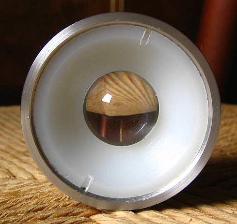
Here you can see the front side, with the lens and the plastic lens
holder ring installed. The holder ring is externally threaded and has
two notches, which allow it to be installed (and removed, if
necessary), using a spanner tool.
Note that the magnifying power of the lens makes the hole in the
aluminium piece appear much larger than it really is! It
looks as
if it were the full diameter of the lens, while in fact it's very much
smaller!
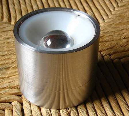
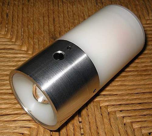
And another picture of the same parts assembly, seen from the side.
The aluminium surface appears quite polished. This was done simply with
some fine steel wool, while the piece was still rotating in the lathe.
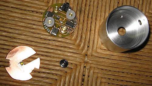
And here you can see the finished aluminium part, complete with all its
holes, and the other parts that go into its backside.
There are four countersunk holes in the side for the screws that will
hold this piece to the plastic part of the body. Also there is a larger
hole for the pushbutton, and two M3-tapped holes through the center
wall of the piece, that will take up the screws.
The copper plate with the LED soldered to it goes in first, LED side
down, so that the LED ends up sitting in the middle of the center hole.
Thermal compound is applied between the copper plate and the aluminium
piece, with care to avoid applying too much, that would squeeze into
the optical path. Then the little black plastic button goes
into
the button hole. I turned it with a rim that keeps it from falling out,
and with a size such that it just sits flat with the aluminium surface,
so that it's hard to inadvertedly switch on the flashlight by
bouncing it around.
The PCB goes in last.
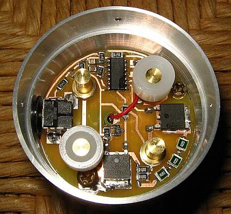
And here it's all assembled. The two screws are in, the black button is
held in place by the pushbutton switch, and the LED's positive pad
looks through the hole in the PCB, allowing to solder a thin wire to it
that connects that pad to the board!
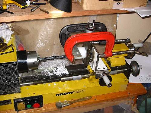
Now lets make the main plastic body piece. I used polyethylene, because
it's the cheapest plastic one can get, it's very easy to work with, and
while it's very soft, that's not a problem in this application.
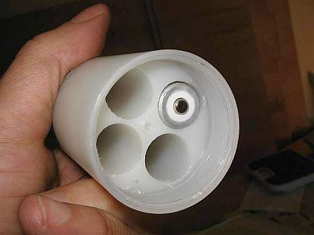
This piece is basically a cylinder with four holes in
it, which
take up the four AA batteries. The big challenge is drilling these big
holes, without getting the crooked, without melting the plastic,
without damaging the thin walls between the holes, and so on. This
photo illustrates how I did it: I configured my lathe as a milling
machine, and had to use good old improvisation skills to come up with a
setup that would properly hold the plastic piece in place during
drilling!
This 15mm drill bit is so long that my small lathe was taken to its
limits!
The rest is simple. On the outside this piece is a cylinder with a
slighly thinner section at its front, where it connects to the
aluminium piece, and with an inner thread at its rear end.
This is the rear side of this plastic piece, with one of the batteries
inserted. You can see the thread. There is still some deburring to do,
and a guide hole for the rear cover contact plate needs to be drilled.
By the way, the threads used in this lamp have a pitch of one
millimeter, at oddball diameters according to what each piece needs.
The plastic and aluminium pieces are already joined in this photo.
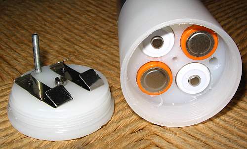
Now the guide hole has been drilled, and you can see the back cover.
Note that this back cover consists of a threaded plug, on which a
freely rotating contact plate is mounted, which carries two
nickel-plated steel contact springs which complete the series
connection of the four AA batteries.
The central hole of the contact plate is drilled a little larger than
the screw that goes through it, and the thread for that screw in the
back piece is cut a bit short. So the screw binds when screwing it in,
ending up secured, without pressing down on the contact plate, which
can rotate freely around this screw.
The contact plate carries another bolt, that pokes into the guide hole
of the big plastic piece, to align the contacts with the batteries, and
keep them aligned while the cover is screwed into the main body. This
bolt completely avoids the risk of placing the contact plate in a
90-degree shifted position, which would short out two of the batteries.
Clever, isn't it? And despite being clever, it actually
works! :-)
Well, to copy my clever design, of course you need the plans. So here
is the AutoCAD drawing
I made while designing this lamp. You will need either AutoCAD, or some
free viewer that can access .dwg drawings. You can better understand
the assembly, and get all the main dimensions, from this drawing. The
drawing does not show every detail, for example the screws are not
shown, but it gives enough information to build this project.
 Testing
and use
Testing
and use
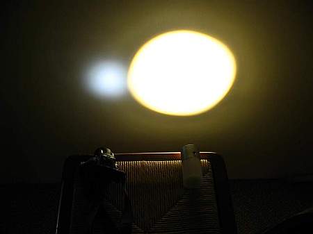
This photo tells a lot about this flashlight! It shows a
side-by-side comparison between my new homemade high power flashlight,
on the right, and a commercial "super high intensity" flashlight
on the left, that has nine common small LEDs and is about the
same size as mine.
The difference in light intensity is pretty obvious, but there are
several more differences. The light of the commercial LED light is
bluish, while that of the Cree LED used in my lamp is quite close to
true white. It looks a bit yellowish here, because I was shining it on
a light brown wall, but it is really a very nice and neutral-appearing
color, being just slightly more yellow than pure daylight, and very
much less yellow than the light of incandescent lamps.
The difference in beam width is also obvious. This is of course a
matter of preference and application, but in almost every situation I
have been in, the typical narrow beam of most commercial flashlights is
much too narrow.
Note also the definition of the beam, and evenness of illumination over
it. Mine is quite well defined and even, although slightly squarish,
because the Cree LED has a square emitting surface and my lens
basically projects an unsharp image of this LED. At longer
distance the spot tends to round out. The commercial flashlight instead
produces a poorly defined spot with an approximate gaussian
distribution across it.
I built this lamp several months before writing this web page about
it. In this time I have used my new flashlight on several wilderness
trips, and I have also extensively used it as a work light in crammed
places where it is hard to get other lamps in. It does a very good job
as a worklight, also to walk in dark places in the night (the low power
setting provides more than ample lighting for that), and I have used it
for room lighting in a mountain refuge, by sitting the lamp on its back
end and reflecting its light off the ceiling. It works very
well
in all these uses.
When using this lamp outdoors, its light is so intense that many people
liken it to a car's headlight! When comparing it side-by-side to an
actual halogen car headlight though, one can see that the car
headlight is stronger - but not by very much!
If I ever make a version 2, I would change just a few things:
- I would add some bump or nook or something to more easily find the
pushbutton in the dark. It takes some fiddling to find!
- I might add a lanyard, as a safety strap when using it aboard a boat
or other places where it could be lost if it falls down.
- I would certainly devote a little more time into making it nicer to
look at, for example by cutting some decorative rings into its body,
with the lathe! And maybe I would even use a plastic having a nicer
color than this plain milky white stuff!
Back to homo ludens electronicus.