Accelerometer
 Many machines cause
vibration. Usually this is undesirable. Through improved balancing,
mounting on dampers, avoidance of resonant parts, and other measures,
it's very often possible to reduce the vibration to an acceptable
level. But when working on such a machine, it might be hard to guess,
by sight and feel, how much the vibration really is, and whether or not
it is improving through the work one is doing.
Many machines cause
vibration. Usually this is undesirable. Through improved balancing,
mounting on dampers, avoidance of resonant parts, and other measures,
it's very often possible to reduce the vibration to an acceptable
level. But when working on such a machine, it might be hard to guess,
by sight and feel, how much the vibration really is, and whether or not
it is improving through the work one is doing.
An instrument to measure vibration is then necessary. This is called an
accelerometer, because it measures the acceleration of the vibrating
parts. This is typically more useful than measuring the amplitude of
the vibration.
I built a simple accelerometer, triggered by my sister's need to track
down a machine in her neighborhood that robs her sleep by making the
walls vibrate in the night; but I also intend to use this meter to keep
track of the wear of my turbogenerator's ball bearings, among other
uses.
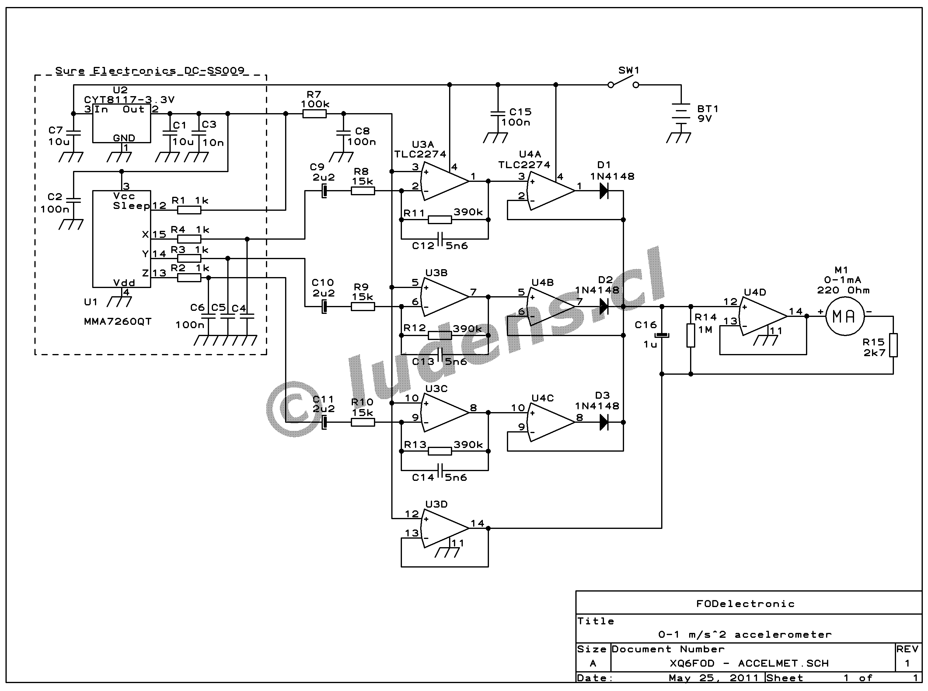
This is a very simple meter. It uses a monolithic three-axis
acceleration sensor with on-chip signal conditioning, which I built
into a little plastic case, along with a galvanometer and the necessary
electronics in between. The whole battery-powered instrument is simply
laid on the machine whose vibration is to be measured, or is held
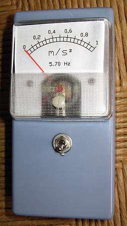
against the vibrating wall. It has only a single scale, covering
accelerations of zero to one meter per second squared. The only control
is the power switch. The frequency range over which it has full
sensitivity spans 5 to 70 Hertz, which covers the frequencies at which
most machines exhibit their strongest vibrations. Outside this range,
sensitivity falls off at a rate of 6dB per octave, and above 150Hz it
falls off much sharper. The value indicated on the scale is the RMS
equivalent value of a sine wave vibration, present in the axis that is
vibrating the strongest. That means, this instrument joins the three
axes and always displays the highest value from among the
three.
This accelerometer could even be used to measure earthquakes, but a
significant portion of a typical earthquake's spectrum falls below 5Hz,
so the sensitivity will be a bit lower than it should. If you want to
use this meter to measure earthquakes, you should expand its
low frequency response by increasing C9, 10, and 11, at the cost of
higher noise. That would also require slowing down the decay rate, by
increasing C16.
The noise level of the sensor I used is about 0.05 m/s^2. Any vibration
to be measured must be clearly stronger than this, or it will be buried
in the meter's noise, and thus undetectable.
 You
can click on this schematic to get a higher resolution version, for
printing.
You
can click on this schematic to get a higher resolution version, for
printing.
The sensor chip is an MMA7260QT. Since this IC is a surface mount
device that has connection pads under the body, it's hard to solder
with hand tools. When I bought it, I still had no reflow soldering
equipment, so instead of buying the chip alone, I bought a little
module offered by Sure Electronics on eBay, that has the chip mounted
on a little circuit board, along with a 3.3V regulator and bypass and
filtering components. This module can be easily integrated into the
rest of the circuit, which I built on universal prototyping board.
The circuit is pretty simple: Each of the three outputs of the sensor
is amplified by independent frequency-shaping amplifiers, and then the
three signals are joined in superdiode circuits that react to the
highest peaks present in any of the three channels. There is a one
second time constant filter, and then a 0-1mA galvanometer as display
device, with the appropriate voltage followers in between. The op amps
are directly powered from a 9V battery, and their bias voltage is
simply taken from the regulated 3.3V present in the sensor module.
There are no trimpots to calibrate the instrument. I don't have access
to any well calibrated reference accelerometer, so there would be no
point in playing with a trimpot and guessing where to set it. Instead
the resistor values were calculated so that the meter will show a
reasonably accurate RMS value of acceleration, assuming that the
vibration has a sine shape, and that the sensor chip actually
produces the output level stated in its data sheet. This seems to be
true, to a level that is good enough. But if the galvanometer you get
has a much different internal resistance than the one I got , which has
220 ohms, then you would have to change R15 accordingly, to
maintain proper sensitivity. The gain of the circuit is set so that if
the resistors and the sensor chip are all accurate, then exactly 2.814
volts across the combination of the meter and R15 should produce exact
full scale deflection. So you can see that my 2.7k resistor should
really be 2.594k, but I don't care for the tiny difference... and
anyway I used 5% resistors, so the uncertainty is larger!
Maybe this circuit is useful to you just as it is, or maybe you will
want to make additions or changes, depending on your needs. If you need
to measure the vibration separately in the three axes, it's a simple
matter to separate the channels in this circuit. You might also want to
add more scales to expand the measurement range. Be aware that you
cannot obtain greater sensitivity with this sensor,
because its
internal noise level is about 0.05 m/s^2. But you could perfectly well
add scales for higher accelerations. The sensor chip can be
configured to several spans, the most sensitive being 1.5 G (roughly 15
m/s^2), used, here, with the highest range topping out at 6 G. Also the
amplifiers
can be programmed for lower gain, by modifying the resistor values. Of
course the values of the capacitors in the amplifier circuits would
need to be modified accordingly, to maintain the desired frequency
response.
If you modify the circuit to measure high levels of vibration, of
course you will need to place the sensor module in a unit that's
separate from the box carrying the galvanometer! Otherwise the severe
vibration will damage the meter... But for the low vibration levels I
want to measure, it's fine to have everything in an integrated unit.
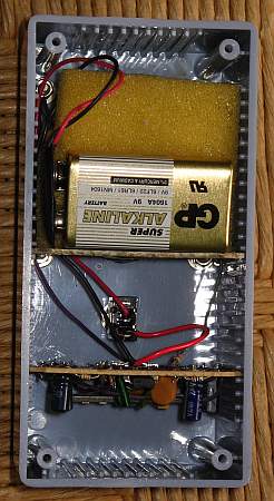 I built the instrument
using a ready-made plastic case. These are inexpensive, and very
practical, because they come internally ribbed so that PCBs can be
inserted in the
grooves, without requiring further fastening.
I built the instrument
using a ready-made plastic case. These are inexpensive, and very
practical, because they come internally ribbed so that PCBs can be
inserted in the
grooves, without requiring further fastening.
The 9V battery sits on the galvanometer, held in place by a piece of
scrap board and some plastic foam, which keeps it from rattling around.
The wiring is very simple: Only the battery, power switch and meter are
wired to the board. Everything else is on the board.
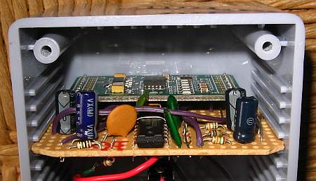 The
circuit was assembled on a piece of prototyping board that has a copper
pattern just like the solderless protoboards. I find this pattern the
most useful, and anyway these prototype PCBs are by far the most
convenient way to build simple one-of-a-kind circuits.
The
circuit was assembled on a piece of prototyping board that has a copper
pattern just like the solderless protoboards. I find this pattern the
most useful, and anyway these prototype PCBs are by far the most
convenient way to build simple one-of-a-kind circuits.
The Sure Electronics module is mounted just as if it were one more
component.
All of the small components (resistors, capacitors, diodes) for this
meter were recycled from junked electronic equipment. Old video
recorders, TVs, monitors, and other things, are a great
free source of lots of components. If you still don't
have a big junk box full of such electronic waste, it's high time that
you go and visit your local TV repairman, and ask him for some! With
modern consumer electronics being so cheap, a great many devices are
never repaired, and accumulate at the repair shops. Usually the shop
owners are happy to give them away for free, and recover the space they
took up!
I drew the meter scale in AutoCAD, printed it on plain paper with my
inkjet printer, and stuck the new scale on top of the galvanometer's
original scale, which is graduated in 0 to 1 milliamperes, using double
faced adhesive tape. There are also some freeware programs out there
that specialize in drawing meter scales, but being used to
AutoCAD, I prefer using it for all sorts of mechanical drawings,
including meter scales!
Back to homo ludens
electronicus.