Building an SDR around a Red Pitaya
This page is not about a finished project, but is rather a
sort of blog about a work in progress.
Introduction:
Over the last several decades radio technology has been moving in the
digital direction, like so many other things too. Digital signal
processing (DSP) started becoming commonplace in amateur radio
equipment from about 1990 on. At first DSP was only used to do the
demodulation, modulation, some of the filtering, and very specially,
doing kinds of filtering that cannot be done with analog technology,
such as non-coherent noise reduction. Such radios were conventional in
that they had frequency synthesizers, mixers, amplifiers, analog
automatic gain control circuits, worked as multiconversion
superheterodynes, until finally feeding the last IF signal into the DSP
system, typically at near-audio frequencies.
As technology advanced, more and more of the receiver (and transmitter)
chain was moved over from analog implementation into digital,
software-based systems. We started calling such things Software-defined
Radios (SDR), since really the software running at a given time defined
most of the characteristics of these transceivers.
The older generation
of SDRs still had a conventional receiver front-end, with an oscillator
or frequency synthesizer, and typically it would convert the RF signal
into two low (or zero) intermediate frequencies (IF), one of them in
phase and the other in quadrature (90 degrees off phase). These I/Q
signals would be converted to digital format and fed into the DSP.
Further technological advancements made it possible to move the frequency
down-conversion into the digital realm too. Such radios essentially take
everything that comes in from the antenna, digitize it, and do all
further processing digitally. They need fast analog to digital
converters (ADC) having enough resolution (14 bits as a minimum, 16 or
more bits is better), and since the amount of digital data coming out
of the ADC is more than what even a pretty fast computer can
handle,
it's first applied to a Field-programmable Gate Array (FPGA) , which is
basically a chip that has lots of configurable logic gates, adders,
multipliers, memory, etc, which are configured and interconnected by
programming. This FPGA is then used to synthesize a frequency with
numerical I/Q outputs, multiply (mix) those outputs with the data coming from the
ADC to produce two low or zero frequency IF signals, and then apply a process of sample rate reduction while gaining
resolution, which downsizes the bandwidth while gaining dynamic range,
and very importantly, reduces the amount of data to a level that a
computer can handle. After this point, a computer does all the
remaining processing. And in transmisison, simply the whole procedure
is done in reverse.
SDRs have a lot of advantages over conventional radios: The ability to
see spectral graphs of an entire band while operating, very
sharp
and infinitely configurable filtering, some filters that cannot be
implemented in small bandwidth radios (such as noise filters that can
tell static crashes from desired signals by detecting their wideband
nature), the AGC and ALC can be made highly effective and free from
attack overshoot, and many more. On the technician's side, there is a big
advantage in the fact that software doesn't go out of alignment, nor
does it wear out and fail! An SDR requires only minimal setup after being built,
and for the most part will never need realignment. This very stability
is what makes highly accurate filters possible!
SDRs also have disadvantages, of course: The leading one is probably
their latency. Unlike analog radios that process signals in realtime,
digital data is processed in blocks at several steps. So first a data
block has to be created, spanning a certain time of the input signal, then it's processed
while at the same time the second block is being filled with fresh data, and
only then is the first block delivered to the speaker, starting at its
beginning. In many cases there are more steps in the processing, such
as sending the pre-processed data blocks from an input card to a
computer for further processing, so that the total delay (latency) of
an SDR can be several times the amount of time required to fill one
data block. By good design, and using small data blocks, latency of
SDRs can be reduced to pretty good figures, and analog radios also have
some latency, mostly caused by their crystal filters - but still most
SDRs have longer latency than most analog radios. So they may not be
usable for certain communication modes that depend on very short
latency, for example modes that require very fast TX/RX switching.
Another disadvantage perceived by some older hams is the "mouse effect":
These people enjoy having large radios on their desks, with a front
panel having as many knobs and buttons as possible. Very specially they
demand a big, nice-feeling, round and hefty tuning knob, and despise
what they call "mouse radios". Well, it's true that an SDR can be
100% controlled just by a mouse, clicking at different things shown on
a screen, and very often exactly this is done. Instead of rotating that big tuning knob, you click on a
spectrum display and drag it to tune over a band, or you simply click
on a signal you see, to instantly tune it in. The fact is that most
people get to love this functionalty after just a few days using an
SDR, so much so that an old-fashioned tuning knob soon seems very old
and cumbersome to them. But for those diehards who cannot live without
a tuning knob, well, it is entirely possible to set up such a knob with
an SDR! Still some people who haven't ever even tried "mouse radios" keep
saying that radios shall have knobs, and lots of them...
When SDR was starting to be a really hot topic, a widely dispersed
group of hams started developing an open-source high
performance
SDR. The first steps of the project were still based on a conventional
analog downconverter feeding a low IF as I/Q signals into a soundcard,
but very soon the main project became a direct-sampling SDR.
The
OpenHPSDR hardware consisted of several separate cards, such as a
receiver, a transmitter, an USB interface, an ethernet interface, a
sound card, etc, that could be plugged into a backplane. The whole
setup was connected to a PC running Windows and PowerSDR or similar
software, and after adding a power amplifer, filters, and TX/RX
switching, the result would be a complete, functional, high performance
SDR.
A ham wanting to assemble his HPSDR faced several difficulties: The
availability of these modules, as kits or ready-made, has been rather
poor. Completely building one's own from published data is really hard,
because multilayer circuit boards and many tiny SMD parts are
used, a good number of which aren't easy to find. And lastly, the whole
thing is very expensive, far more expensive than buying a pretty good
factory-made transceiver!
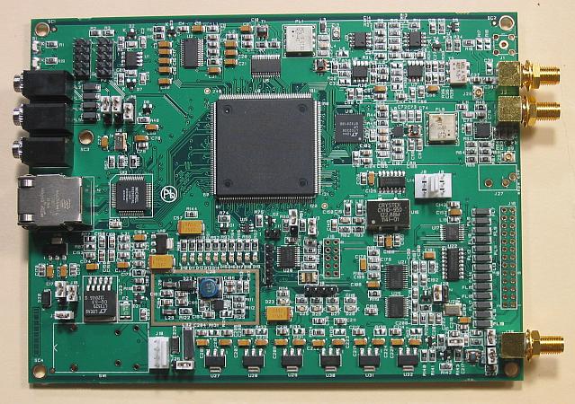 What
significantly eased this situation is the development of the
Hermes board, which is essentially the entire openHPSDR on a single card, replacing the separate
receiver, transmitter, interface and backplane cards. So now it became
possible to get into OpenHPSDR by just buying a Hermes card, adding a
power amplifier, filters, switching, connect it to a PC, and get on the
air. And the Hermes card was available for quite some time -
but
the price was stiff, at close to US$1000 plus international shipping
plus taxes. So a complete radio built around a Hermes board would still
be more expensive than a factory-made radio. And last time I checked
(May 2017), the Hermes seems to be no longer available! But there are a
fair number of Hermes cards around, and some become available
second-hand.
What
significantly eased this situation is the development of the
Hermes board, which is essentially the entire openHPSDR on a single card, replacing the separate
receiver, transmitter, interface and backplane cards. So now it became
possible to get into OpenHPSDR by just buying a Hermes card, adding a
power amplifier, filters, switching, connect it to a PC, and get on the
air. And the Hermes card was available for quite some time -
but
the price was stiff, at close to US$1000 plus international shipping
plus taxes. So a complete radio built around a Hermes board would still
be more expensive than a factory-made radio. And last time I checked
(May 2017), the Hermes seems to be no longer available! But there are a
fair number of Hermes cards around, and some become available
second-hand.
The Hermes board does all of its processing in a single, large FPGA.
The program for this FPGA can be loaded from the host computer. Hermes
uses a 16-bit ADC and DAC, running at 122.88 MHz.
The OpenHPSDR hardware is most commonly used with a special version of PowerSDR,
the same software used for years by FlexRadio, a commercial
manufacturer of SDRs. For the communication between the software
and HPSDR hardware a protocol was defined, that originally
worked
over an USB connection. This protocol was enhanced many times, to add
features and improve performance, and eventually was grafted onto
ethernet connections, by simply putting the data packets prepared for
USB into wrappers so they can be sent over ethernet, using UDP frames.
Later a new protocol was developed, that allows for more features, and
more quality. The new protocol is defined specifically for ethernet, separates data
streams and uses different logical ports, allows a large number of
simultaneous receivers, and so on. As far as I understand, currently
existing hardware and software still uses the old protocol.
The Red Pitaya:
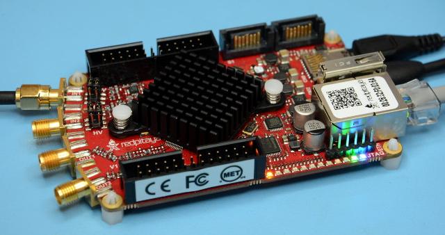 In
2013 a group of clever people in Slovenia got together and
developed the Red Pitaya, as a Kickstarter project. The aim was to
offer it as a highly educational, user-programmable fast dual-channel
input/output board, to be used as oscilloscope, spectrum analyzer,
signal generator, and so on. It turns out that the Red Pitaya has
everything on board that's needed to use it as the core of an SDR,
almost as a direct replacement of the Hermes board. And soon Pavel
Denim developed several programs for the Red Pitaya that allow doing
precisely this!
In
2013 a group of clever people in Slovenia got together and
developed the Red Pitaya, as a Kickstarter project. The aim was to
offer it as a highly educational, user-programmable fast dual-channel
input/output board, to be used as oscilloscope, spectrum analyzer,
signal generator, and so on. It turns out that the Red Pitaya has
everything on board that's needed to use it as the core of an SDR,
almost as a direct replacement of the Hermes board. And soon Pavel
Denim developed several programs for the Red Pitaya that allow doing
precisely this!
The Red Pitaya has some disadvantages and some advantages relative to
the Hermes board. For example, it only has 14-bit ADCs and
DACs running at
125 MHz, compared to the 16 bits boasted by Hermes - but it has two
channels of each, compared to the Hermes' single channel! I understand
that the Red Pitaya's FPGA is significantly smaller than the Hermes',
but then the Red Pitaya has a dual-core ARM CPU built in, with lots of
memory, and runs Linux! And the biggest difference to Hermes: It costs
only one third as much. And this means that it is possible to build an
SDR around a Red Pitaya for less money than an equivalent factory-built
radio would cost. You cannot do that with a Hermes, at least not with a
Hermes bought new.
My SDR project:
In early 2017 I decided that it was time for me to get seriously into
SDR, and after confirming that the Red Pitaya was my best option, I
purchased one. My final goal is to put together an SDR having the
following fundamental characteristics:
- 160 to 10 meter coverage (6m would be possible too, but is pretty
irrelevant to me, so I prefer to leave it out to ease the transmitter section);
- Legal limit RF output power (that's 1200 watts in my country);
- High efficiency power amplifier, most likely class E running in EER
mode;
- Built as "black-box" radio connected to a PC at first, and in a
second step build a small embedded PC right into it to make it stand-alone;
- Keep everything as low-cost and simple as possible.
The PowerSDR software has specific support for EER (Envelope Elimination
and Restoration) transmission, and also has an adaptive predistortion
system to correct nonlinearities of the TX power amplifier chain.
And Pavel Denim made a program that allows
the Red
Pitaya to emulate the Hermes board. So this all seemed to be fitting
together pretty well. Just keep reading, and see my further adventures
and blues in this area.
Buying the Red Pitaya:
When I went shopping for the RP on the web, my first discovery was that
there was no place where one could buy it! It turned out that the
company making it had stopped selling the card by itself, and is
instead packaging it into kits, called STEMLab. The most basic kit, the
"starter", includes a power supply, adapters, a cable, and a preloaded
SD card, and already costs significantly more than a bare RP would. Oh
well. More complete kits include oscilloscope probes and other
accessories, which are absolutely not needed for SDR use, and they are
much more expensive. And there is a trap: STEMlab kits are sold in
125-14 and 125-10 versions. The -10 versions only have 10-bit ADCs and
DACs, and also have less memory! They are useless as SDRs, due to their
insufficient dynamic range.
So, if you are shopping for a Red Pitaya card for use as an SDR, buy a
"STEMlab 125-14 starter kit". That gets you the correct Red Pitaya
card, plus power supply and SD card, for the least possible money.
Most distributors I checked were out of stock when I tried to buy this.
Even the manufacturer's webstore was out of stock! The two I found that
had the RP available were both located in Germany. So we (CE6SAX and I)
placed an order with Reichelt in Germany.
Soon we got our RPs.
First impressions:
Firing up the Red Pitaya for the first time was pretty easy: Insert
the SD card (which acts as hard disk for the RP's Linux system), connect
the power supply, connect the network cable to my router, and apply
power. The LEDs gave their proper signs of life. The
instructions ask
for installing a certain third-party printer sharing utility that
allows connecting to the RP by its hardware address. This didn't work
for me, and it's totally unnecessary: One can perfectly well connect to
the RP using its IP address rather than its hardware address. The RP by
default gets its IP address via DHCP from the router, so connect to
your router, look at its DHCP client table, and you will find
what
IP address it assigned to the RP. Then point your web browser at this
address, and you will get the RP's screen. To avoid having to look up
each time which IP address the RP got assigned, it's typically more
convenient to configure the RP to use a fixed IP address. More about
this later.
Via the browser you can see which applications come preinstalled -
which doesn't mean that you can use all of them, as some require paid
"activation". My advice: Just don't use those. Instead navigate to the
user-contributed applications, and download what you want to use. You
will find oscilloscopes, spectrum analyzers, signal generators, various
other test instrument applications - and also several SDR applications.
Simply download what you want, and a moment later you can run them.
They are saved to the SD card, so next time they will be there - you
just need to start them each time.
After doing this much, the RP's tiny heatsink will be hot enough to
cook some eggs on it. In the interest of long-term reliability, it's
highly advisable to purchase a little fan that fits the heatsink and runs
from 5V. Such fans can be bought cheaply on eBay and elsewhere - try to
find a quiet one. A connector that provides power for the fan is
provided on the RP. While you are waiting for that fan to arrive, point
any other fan at the RP, to keep it cool. And in your definitive SDR,
plan on mounting the RP against a larger heatsink, part of the box, or
buy the special RP box, which also acts as heatsink - because tiny fans
are notoriously unreliable, and a dead fan might only be noticed when
the RP fails from overheating!
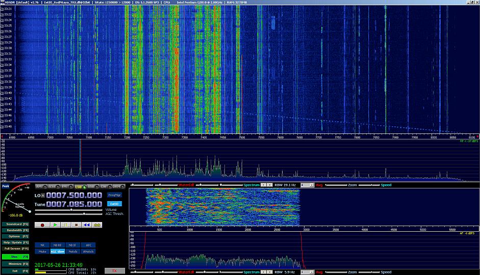 There
are several SDR programs available that can use the RP. Since
I had already installed HDSDR (Note: This is an SDR program,
NOT
compatible with the HPSDR!), which I used with the cheap RTL-SDR
dongle before, and noticing that there is an HDSDR-compatible transceiver
application by Pavel Denim available for the RP, I downloaded and tried
that first. One has to download a driver library too, named
ExtIO_RedPitaya_TRX.dll, and copy it into the HDSDR directory. Then
HDSDR gave me the option to select between the RTL-SDR and the Red
Pitaya, and I got my first SDR experience with the RP: Wow!
There
are several SDR programs available that can use the RP. Since
I had already installed HDSDR (Note: This is an SDR program,
NOT
compatible with the HPSDR!), which I used with the cheap RTL-SDR
dongle before, and noticing that there is an HDSDR-compatible transceiver
application by Pavel Denim available for the RP, I downloaded and tried
that first. One has to download a driver library too, named
ExtIO_RedPitaya_TRX.dll, and copy it into the HDSDR directory. Then
HDSDR gave me the option to select between the RTL-SDR and the Red
Pitaya, and I got my first SDR experience with the RP: Wow!
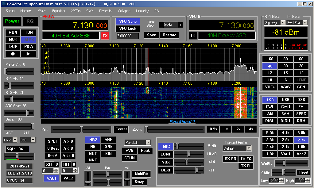
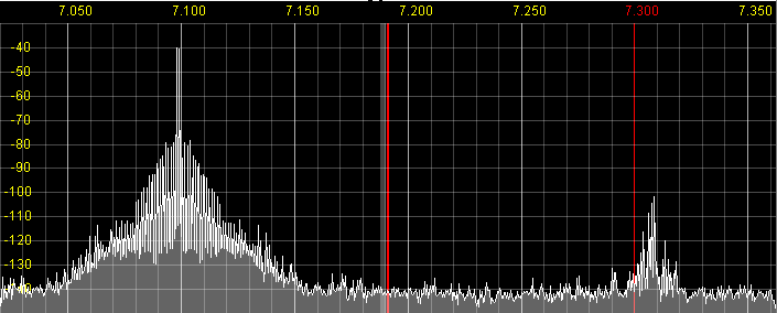
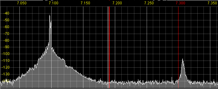
In this screenshot a 1250kHz wide swath of spectrum, including the 40m
ham band and the 41m broadcast band, is visible at once. A ionosounder
signal sweeping through the band left a clear track on the waterfall
display. Below are a spectrogram and waterfall of the demodulated audio
signal on 7085kHz. The bandwidth is adjustable by dragging the filter
slopes with the mouse, tuning is by clicking on the desired signal or
by adjusting the numerical frequency display. The S-meter, once
calibrated, is accurate over the full range, and the reception quality
is superb.
HDSDR is an excellent program for general receiving, and in fact I
prefer it over all others I have tested so far. But it doesn't provide
much transmit capability, just the most basic - which I
haven't tested yet - and isn't really
designed to act as a transceiver controller. So, PowerSDR (freeware) or
perhaps Zeus Radio (payware, with free limited demo available) or some
other program of that sort need to
be used for a ham transceiver. This requires downloading and running
Pavel Denim's HPSDR-compatible transceiver software for the Red Pitaya.
I did that, but ran into trouble with the PC software: Neither PowerSDR nor Zeus would
install on my machine!!!
I had Windows XP SP2 on my PC, and despite all blah blah about it being
outdated and almost criminally dangerous to use due to termination of support
by Microsoft, it still serves me very well, has never gotten infected,
and an attempt to upgrade to Windows 7 Ultimate some time ago failed
miserably, as the installation DVD of Win7 I could get refused to upgrade my existing system and insisted
on a clean installation, then many of my programs and drivers (I use
more than 200 different programs) wouldn't run on Win7, and Win7 had
several nasty bugs for which there were no fixes, and would phone home
all the time without really letting me control that. So out it went, I
restored my XP installation from the backup, and since then
hadn't
done any further attempts at upgrading.
I found hints that PowerSDR could run in XP, but only when SP3 is
installed. I had tried installing SP3 some time ago, before that
attempted upgrade to Win7, but it failed to install. Now I tried again.
It failed again. After spending lots of time on this issue, I was
finally able to find a version of SP3 that installed correctly on my
specific version of Windows XP SP2 - there are more different and
incompatible versions of Windows XP and SP3 out there than
you might think!
PowerSDR installed without any problem on Windows XP SP3. Zeus
Radio didn't.
Red Pitaya software and configuration:
Downloading Pavel's programs from the Red Pitaya website, directly to
the Red Pitaya, works fine, but requires starting the program via a web
browser every time the RP is powered up. If the RP will be used mostly
or only for SDR, it's far more practical to have the relevant RP
program self-start right after powering up the RP. This can be easily
done by downloading the relevant SD card image file from Pavel's website,
and unzipping its contents onto an empty, FAT32-formatted SD card. This
card will then contain a version of the RP operating system and the
preinstalled applications, and in addition, invisible on a web browser
accessing the RP, Pavel's software will be running. If you start
another RP application rom the browser, Pavel's program is aborted, but
power-cycling the RP will restart it.
To unzip the image file onto an SD card, you need nothing more than a
zip program such as WinZip, and an SD card reader/writer. If you don't
have such an SD card reader, you can use almost any digital camera in
its place!
The documentation says that the SD card for the RP needs to be at least
4GB in size, and have a speed rating of class 10. But what actually
gets copied to the card is far less, only about 70MB! I read somewhere
that the full development environment needs the 4GB card, but to just
run RP applications you don't need that. In fact the SD card that
was delivered in my STEMlab kit seems to be one of those Chinese eBay specials:
It claims 4GB capacity on the label, but its actual capacity is just
120MB! Still that's plenty to hold the "Red Pitaya Ecosystem" along
with a good number of applications.
Update (2017-7-3): The SD card delivered with the RP is not
a fake! It just comes formatted to far less than full capacity. If you
want to reformat it to its full size, download the program
"SDFormatter". Put the card in a card reader, copy all of its contents
to a zip file (with folders), then use SDFormatter to format the card,
choosing " full overwrite format, format size adjustment on". This will
format it to full size. Do not choose quick format, because that will
produce a card that seems to have full capacity, but fails to write
beyond the previously formatted size! After this you can expand your
zip file back onto the card, and it will run in the RP as good as it
did before, but with a huge lot of extra capacity for adding programs
and storing data. My thanks go to Gerald, DL3KGS, for hinting me at this, and suggesting SDFormatter!
It might be a good idea, although not essential for a plain user of RP
software, to download and install some programs to access
the Red Pitaya's Linux system. PuTTY can be used to open a console connection
to the RP. Log in as "root", password "root". You need to be fluent in
Linux to do anything there. And WinSCP can be used as a file
manager, editor, etc, for the RP, working very much like any other file
manager. Both of them work over the ethernet connection - you don't
need to add an USB connection to the RP, even if that's yet another
option.
If you let your router dynamically assign an IP address to the RP, it
might get a different address each time, if there are various other
devices connecting and disconnecting from the router. So you might have
to ask the router every time at which address your RP landed! That's a
nuisance. In such cases it's better to configure the RP for a fixed IP.
Also if you
want to connect the RP directly to the PC, without a router, you need
both the PC and the RP to have fixed IP addresses. The PC can be
configured via the Windows Control Panel. The RP is configured by
editing a file named interfaces,
located in the etc/network
directory. The file has comments in it making it self-explanatory,
although after setting the RP for a fixed IP I couldn't make it connect
to the web anymore, although it worked fine with SDR software. The interfaces
file tells that one should make changes also to another file, but I
couldn't find what to change inside that one... and that's likely to
have been the reason why web connectivity was lost. Anyway, I it back
to DHCP for now.
You
can edit the configuration either through WinSCP, with the SD
card installed in the
RP, and first issuing a "rw" command via PuTTY to make the SD card
writable, or you can put the SD card into your card reader and edit the
file
with any Windows text file editor. The latter is much easier.
Red Pitaya modifications:
The RP has oscilloscope-like inputs, with an input resistance of 1MΩ in
parallel with a small capacitance. It can be jumper-configured for two
different input ranges, the more sensitive one being ±1V. This doesn't
suit radio work very well. 50Ω inputs have the advantage that the
length of coax cables doesn't affect the frequency response, and the
sensitivity provided by a 14-bit ADC scaled for ±1V is not
satisfactory for radio reception, except on the lowest bands in
the
evenings when the propagation is strong. So some minor modification is
convenient, if the RP will be used only or mainly as an SDR.
The first thing that can be done is very easy: Even the ±1V range is
obtained by
configuring an input voltage divider for a 2:1 ratio. By removing one
of the jumpers, and placing the other over the two center pins of the
6-pin block, the RP is configured for an input range of ±0.5V. That's a
6 dB improvement, for free! The input impedance in this configuration
is still
very high, so if desired one can solder a 51Ω resistor across
the input connector, to achieve a nominal 50Ω, DC-50MHz, almost
flat input response with a
±0.5V range.
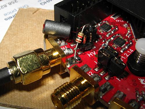 But the
card's high input impedance allows doing better than that. We
can obtain some "passive gain" by using a little RF transformer. There
is a limit to how much can be achieved, because the higher the
transformation ratio, the higher is the output impedance of such a
transformer, and the RP's capacitance will soon limit the frequency
response if we overdo it. But a 3:10 winding ratio is well within
the possibilities. I selected a small binocular ferrite core,
specifically a Ferronics 12-350-J, roughly equivalent to a Fair-Rite
2843002402, also known as Amidon
BN-43-2402. The Ferronics is just a little longer than the Fair-Rite
one. I wound 10 turns of AWG #36 wire on it, tapped at 3 turns. The tap
gets soldered to the RP's input connector pin connection, the 3-turn end is
soldered to ground at the same connector, and the 7-turn end is
soldered to one of the little configuration jumpers. Also a 1kΩ
resistor is soldered from this jumper to ground (at the input
connector), and the jumper is inserted just on pin 5 of the pin block.
For now this trafo is dangling just from its very thin wires, but
since it works so well, I will fix it in place with a dab of hot melt
glue someday when I feel generous.
But the
card's high input impedance allows doing better than that. We
can obtain some "passive gain" by using a little RF transformer. There
is a limit to how much can be achieved, because the higher the
transformation ratio, the higher is the output impedance of such a
transformer, and the RP's capacitance will soon limit the frequency
response if we overdo it. But a 3:10 winding ratio is well within
the possibilities. I selected a small binocular ferrite core,
specifically a Ferronics 12-350-J, roughly equivalent to a Fair-Rite
2843002402, also known as Amidon
BN-43-2402. The Ferronics is just a little longer than the Fair-Rite
one. I wound 10 turns of AWG #36 wire on it, tapped at 3 turns. The tap
gets soldered to the RP's input connector pin connection, the 3-turn end is
soldered to ground at the same connector, and the 7-turn end is
soldered to one of the little configuration jumpers. Also a 1kΩ
resistor is soldered from this jumper to ground (at the input
connector), and the jumper is inserted just on pin 5 of the pin block.
For now this trafo is dangling just from its very thin wires, but
since it works so well, I will fix it in place with a dab of hot melt
glue someday when I feel generous.
This transformer provides a theoretical passive gain of 10.46 dB, and
the 1kΩ resistor combined with the losses in the ferrite core provide a
reasonably accurate 50Ω input termination all over the HF range. On the
160m band this transformer starts running out of sufficient inductance,
so the input impedance goes inductive and low, an effect that increases
at even lower frequencies. This is a desirable behaviour for an SDR
transceiver, as it acts as a progressive attenuator on the MF, LF, VLF and
ULF bands, on which there is usually a huge lot of noise which we want
to keep out of the ADC. It doesn't impair reception of those VLF
signals, because these tend to be extremely strong, but one needs to
keep in mind that the S-meter indication provided by the software will
become progressively inaccurate on frequencies from the 160m band down.
So, input 1 of my Red Pitaya now has a nominal 50Ω impedance, and about 16dB
higher sensitivity than in its stock configuration. Input 2 instead
will only be used for feeding back my transmit signal, for the
predistortion system, and that's well served by the stock ±1V input
range. I just added a 51Ω resistor soldered to the input 2 connector,
in order to have a clean and predictable wideband behaviour when using
coax cables of varying lengths during experimentation and final
equipment integration.
RX front end
I played with the modified RP for several days without adding anything
else, and found the sensitivity (noise floor) to be good enough at all
times on bands from 30m downwards, and most of the time it was also
satisfactory on 20m. But on higher bands clearly some more gain in
front of the ADC is necessary. So I looked into my junk box, searching
for parts suitable to build a preamplifier. I found some J310 JFETs
which would serve beautifully in common-gate preamplifiers delivering a
modest gain, around 10dB, and I also found various low noise RF bipolar
transistors that could be used with gains of 10 to 15dB, but more
attractive was a small set of samples of the MAR series of MMICs
(Microwave Monolythic Integrated Circuit). I picked the MAR-6 from that
set, which has 21dB gain and 3dB noise figure, working pretty much from
DC to daylight as far as HF equipment is concerned. While this is an
antique device, it's still available at low cost at places like RF Parts.
Far more modern and even cheaper MMICs are available at many places,
even on eBay, but I used what I had.
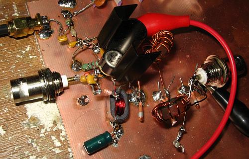
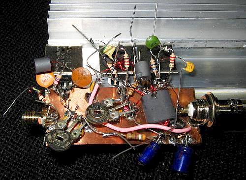
 Using
MMICs
is trivially simple: Apply the well bypassed supply voltage through a
properly calculated resistor, connect DC blocking capacitors to the
input and output - and that's it. I cut a piece of unetched
PCB material as a breadboarding groundplane, and assembled the
MMIC
preamplifier on a corner of this board. The tiny black pill is the
MMIC. Now the RP SDR really came to
life! While on 40 meters and lower just the S-meter deflected more
strongly, on the high bands the SDR started hearing everything my good
old Kenwood TS-450 hears, and then some. I tested the noise floor with
open input, 50Ω-terminated input, and with the antenna connected, and
found that the 21dB of gain provided by this MMIC, along with its noise
figure, are entirely adequate even when propagation conditions
are poor. The
receiver's noise floor ends up 8 to 10dB below the atmospheric noise,
in my very RF-quiet forest location. More gain than this would make no
sense, and would unduly compromise the receiver's dynamic
range. A
few dB less
preamplifier gain might be optimal, but for the moment what I have is
good enough.
Using
MMICs
is trivially simple: Apply the well bypassed supply voltage through a
properly calculated resistor, connect DC blocking capacitors to the
input and output - and that's it. I cut a piece of unetched
PCB material as a breadboarding groundplane, and assembled the
MMIC
preamplifier on a corner of this board. The tiny black pill is the
MMIC. Now the RP SDR really came to
life! While on 40 meters and lower just the S-meter deflected more
strongly, on the high bands the SDR started hearing everything my good
old Kenwood TS-450 hears, and then some. I tested the noise floor with
open input, 50Ω-terminated input, and with the antenna connected, and
found that the 21dB of gain provided by this MMIC, along with its noise
figure, are entirely adequate even when propagation conditions
are poor. The
receiver's noise floor ends up 8 to 10dB below the atmospheric noise,
in my very RF-quiet forest location. More gain than this would make no
sense, and would unduly compromise the receiver's dynamic
range. A
few dB less
preamplifier gain might be optimal, but for the moment what I have is
good enough.
The RP has a 125MHz sampling rate. This causes any signals above
62.5MHz to be aliased into the 0-62.5MHz range. It is thus necessary to
reject those signals before they reach the ADC. The RP only
has very basic low-pass filters built in for the input channels, and the result is
that I
got FM broadcast signals on 88-108MHz aliasing strongly into the
17-37MHz range, and TV signals on VHF channels 3-6 aliasing into the
frequencies above 37MHz. Particularly on the 15 and 12 meter bands I
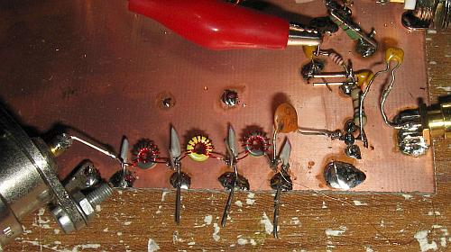
got a lot of QRM from these alias signals. So I added a 7-pole, 32MHz
Chebyshev low-pass filter in front of my MAR-6 preamplifier. I wound
the inductors on tiny T-20-6 cores, because I have a lot of
them.
With this filter in place there is now no sign remaining of any
aliasing.
But my receiver front end has no further filtering so far. The 32MHz
low-pass filter cutting off VHF signals, and the transformer
at
the RP input attenuating MF, LF and VLF signals, is all the filtering
there is. The result is that when listening on the high bands in the
evenings, when propagation on the high bands is very weak but lots of
shortwave broadcast stations on about 5-16MHz are booming in with
S9+30dB signals and more, I get a comb spectrum of little carriers
spaced 5kHz apart. These must be mainly second-order IMD products
caused by nonlinearities mixing the broadcast signals. These carriers
are typically up to about 15dB above the noise floor, so they would be
easy to reject by using very modest band-pass or high-pass filters.
Maybe just a single 17MHz high-pass filter, switched in when operating
on 17 meters and higher, would be enough to cure this problem, but of
course a more solid solution is to either use a set of proper
band-switched band-pass filters, or use a set of high-pass filters that
are combined with the low-pass filters that will be needed at the
transmitter output. Adding these filters is something to be done in the
final SDR. For the time being, during the experimentation phase, this
IMD QRM is unimportant enough to ignore.
An audio CODEC for the Red Pitaya:
 The
Hermes board includes an audio CODEC that provides speaker, headphone
and line outputs, plus microphone input. The Red Pitaya doesn't,
although it does have general purpose slow analog inputs and PCM
outputs, that might be pressed into audio service. PowerSDR by default
uses the audio CODEC of the SDR hardware, although it can also be
configured to use the PC's sound card. To level the field between the
Hermes and the RP, some hams like to add an external audio CODEC board
to the RP. I was given one of them, and while I don't yet know whether
I will use it in my final SDR, it's certainly proving useful for testing.
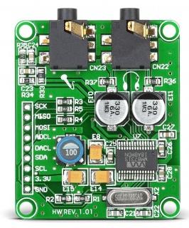
The
Hermes board includes an audio CODEC that provides speaker, headphone
and line outputs, plus microphone input. The Red Pitaya doesn't,
although it does have general purpose slow analog inputs and PCM
outputs, that might be pressed into audio service. PowerSDR by default
uses the audio CODEC of the SDR hardware, although it can also be
configured to use the PC's sound card. To level the field between the
Hermes and the RP, some hams like to add an external audio CODEC board
to the RP. I was given one of them, and while I don't yet know whether
I will use it in my final SDR, it's certainly proving useful for testing.
For example, there is the issue of antenna-to-speaker latency, of much
concern to SDR folks. I was told that using this CODEC is almost
essential, because PC sound cards have an enormous latency. Well, this
proved to be the case only when using standard Windows drivers for the
sound card, such as MME. Indeed they introduced more than 100ms of
additional latency! But using the PC's sound card with ASIO drivers
actually resulted in a tiny little bit less latency than using the CODEC
connected to the RP. So the use of a CODEC board seems to be
entirely optional. People who want to have microphone
and headphone connectors and a speaker right in their SDR black
box
should use it, while those who use either an embedded PC with sound
chip in their SDR, or are happy using a desktop PC with the microphone,
headphone and speakers connected to the PC, will not need this CODEC.
In any case, it's a real plug-and-play solution: I connected it to the
RP as indicated in the instructions, and it immediately worked very
well, with no configuration needed anywhere. WhenPowerSDR is set up to
use the sound card, which it does via a Virtual Audio Cable (VAC), both
the PC soundcard and the CODEC at the RP work at the same time. But the
mic gain control of PowerSDR only acts upon the CODEC, while the gain
of the microphone connected to the PC has to be set via the sound
card's mixer program.
Transceiver control:
Pavel's RP software supports four digital outputs that emulate the ones
Hermes has. The behaviour of these can be freely configured on a per-band
basis in PowerSDR. This allows easily switching RX and TX filters. Also
there are output pins that can be used to switch the RX preamplifier,
and an attenuator. I haven't yet gotten the attenuator pins to work,
but I really haven't tried seriously, because I don't intend to install
a step attenuator. Just switching my 21dB preamplifier in and
out
should be plenty for matching the dynamic range to band conditions, at
least at my rural place.
When not using an audio CODEC, the pins liberated that way can be used
to implement a far more sophisticated control of filters, attenuators,
antenna ports and
other devices, by means of shift registers. I don't foresee to use this
feature, since I don't think I will have any need for it. But it's
there, for those people who want to build a more flexible SDR.
Other digital I/O pins of the RP are used as PTT input, TX/RX output,
iambic keyer input, GPS time sync input, and two slow analog inputs of the RP are
used to read transmitter forward and reflected power. All this is
pretty good and should allow building a practical transceiver that
doesn't need physical switches nor other control devices on the front panel.
Everything can be controlled from the PC.
I discovered a funny bug in PowerSDR, when testing the PTT function:
Using the MOX button on the screen results in loud crashes in the
speaker when switching from RX to TX and back. Instead doing the same
switching via the PTT input of the RP does not result in such crashes. Since one
would normally always use the PTT, this is no significant problem. It's just
funny. One would expect the MOX function to work just like the PTT, but
of course they reach the innards of the software through very different channels...
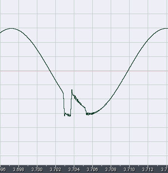
An evil case of popping disease:
While I played with the RP and PowerSDR over days and weeks, a far
worse
problem became impossible to ignore: There is a clicking and popping
appearing both in the audio output and on the spectral display. When
all signals in a band are of roughly the same strength, this problem is
nearly unnoticeable, but when receiving a strong signal on an otherwise
rather quiet band the popping becomes very noticeable. Listening to a
weak signal in the vicinity of a strong one is severely hampered by the
popping. Applying a clean
carrier from a signal generator to the RP and tuning to this carrier
makes the problem absolutely obvious:
I asked other people who use the RP with PowerSDR, and it turned out
that two of them have the same problem, with one of them having noticed
it before, and the other noticing it only when I pointed him to it.
Also one user reported not having this problem. So far these three
reports are the only ones I got. Including me, it's three users getting
the pops, and one not getting them. There must be a true problem.
A web search produced lots of results from people getting the pops when
using PowerSDR with other hardware, such as the FlexRadio
rigs.
I made lots of systematic tests. My results so far are:
- The problem happens exactly the same regardless of whether I use the
PC sound card for audio output, or the CODEC connected to the RP.
- The problem is independent of the CPU load, and that's surprising.
Even when forcing a 100% CPU load by running a video conversion program
at the same time as PowerSDR, the popping does not change.
- Changing the process priority of PowerSDR does not change the popping either.
- Disabling my firewall (ZoneAlarm) strongly reduced the amount of popping, but
did not eliminate it. Disabling other resident
programs, drivers
and services did not change the popping.
- Generating additional traffic over the ethernet, by downloading data
from the internet, does not seem to make a noticeable change in the
number of pops. But this isn't very relevant, because my internet
connection is slow, so that even the most intense web traffic I can
generate is small compared to the traffic between the RP and the PC.
- Connecting the RP directly to the PC, instead of through my router,
makes no difference.
- Changing the buffer size and the sampling rate in PowerSDR has a
strong effect on the problem. Playing with this, I found that switching
between 1024 and 2048 bytes per buffer makes little difference, but
that otherwise there seems to be a relatively linear relationship
between the total number of buffers transferred (sampling rate
divided by buffer size) and the number of pops I get, but there is a
sort of baseline number of pops per unit of time, which cannot be broken by any
setting.
- The sound of each pop changes with the sampling rate, but
does
not change with buffer size. I assume this has to do with
PowerSDR's filter responses changing with the sampling rate.
The
fact that the buffer size has no effect on the sound might indicate that
each pop is caused not by the loss of a complete buffer, but only one
sample. I'm just guessing here...
- When the test carrier is tuned exactly to the center of the spectral
display of PowerSDR, the popping gets so weak that it almost completely
disappears. This is interesting! This SDR is a zero-IF system, that is,
the signal coming out of the numerical mixers (multipliers) in the FPGA
is pure DC when the signal is tuned exactly to the center of the
bandwidth. And a DC signal means that all samples contain the same
numerical value, so that missing a sample, or many, won't change the
audio output! Instead when the signal is tuned even slightly off-center, it
turns into a low frequency IF signal, and missing samples will cause phase
jumps. So, this "discovery" seems to show that PowerSDR is either
skipping samples, or doubling up samples, or changing the order of
samples.
- I checked the latency my computer has in the execution of
time-critical interrupts, using the DPC Latency Checker
program.
This program reported the latency to always stay in the
acceptable
range, and changing settings in PowerSDR that result in more popping
did not affect the measured latency. It doesn't seem to be a DPC latency
problem.
In any case the problem seems to be localized in the data flow between
the RP and the digital signal processing on the PC getting stalled,
delayed, corrupted, or whatever. Is this perhaps a case of buffer
overflow or underflow caused by slightly differing
sampling
rates? After all, the RP and the PC don't have their clocks
synchronized! 192kHz in the RP might well be 0.001% or so different from
192kHz measured by the PC clock. If this isn't correctly handled by the software, data corruption will happen.
Then I tried again running HDSDR instead of PowerSDR,
using Pavel's HDSDR-compatible RP software. There is no
popping
problem at all in that setup, even at 1250kHz sampling rate, which is
much higher than the highest rate supported by PowerSDR! This proves
that there must be either some
bug or some non-optimal implementation of something either in PowerSDR
(more likely) or perhaps in Pavel's HPSDR-compatible RP software (less
likely, I think, given the many reports of popping with PowerSDR and
Flexradio).
The one report I got from a ham who does not get this popping prompted
me to try a newer Windows version. I installed Windows 7 Ultimate on a
clean SSD, then installed nothing else than the drivers for my
motherboard chips, for my sound card, and then PowerSDR. I
configured
Windows 7 for as little internet traffic as I could, and ran tests with
the internet connection disabled, to prevent interference. The result
was interesting: As long as nothing else was done on the computer,
PowerSDR ran pop-free in this setup, but any activity, even if it was
just moving the mouse, resulted in much more popping than under Windows
XP! Also the reaction of PowerSDR to changes in the sampling rate and
buffer length was more critical.
Then I tried to install the demo version of Zeus Radio, and voilá, it
installed fine under Windows 7, after asking me to install a specific
version of a runtime environment. But.... it popped exactly as badly as
PowerSDR does!!!
Now that opens a big question: Is the bug in Pavel's software? Or did
the authors of Zeus Radio copy sections of PowerSDR, which after all is
open-source? In the latter case both PowerSDR and Zeus are affected by
the same bug or non-optimal implementation.
Update about the popping problem (2017-6-29):
 Today
I made some more systematic tests. Using PowerSDR 3.4.1, I captured the
program's audio output while receiving a clean strong carrier, tuning
to a very low beat frequency (roughly 60Hz). I used DSB mode with the
widest possible filter setting, to preserve as much waveform detail as
possible. The result is interesting! It shows very clearly that blocks
of sample data get processed out of order!!!
Today
I made some more systematic tests. Using PowerSDR 3.4.1, I captured the
program's audio output while receiving a clean strong carrier, tuning
to a very low beat frequency (roughly 60Hz). I used DSB mode with the
widest possible filter setting, to preserve as much waveform detail as
possible. The result is interesting! It shows very clearly that blocks
of sample data get processed out of order!!!
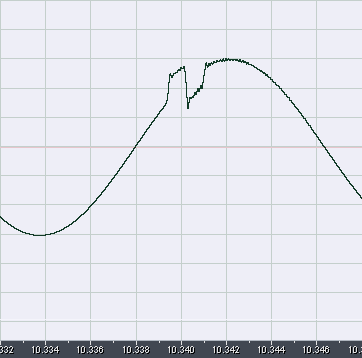
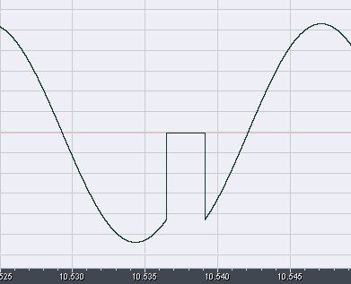
This screenshot shows roughly one cycle of the 60Hz beat note, with one
of the nasty pops in it. After visually filtering out the high
frequency ripple added by the filters, we are left with the simple fact
that two sections of the waveform switched place! Each of these
sections is roughly 0.8ms long. The UDP packets sent by the Red Pitaya
contain 988 bytes of sample data, at a rate of 26 bytes per sample. At
the 48kHz sampling rate I used to capture this waveform, each UDP
packet contains 0. 792ms of data. So what's happening here is that two
UDP data packets were processed out of order!
I tried setting PowerSDR to different sample rates and buffer sizes.
The result clearly indicates that what's being processed out of order
are indeed UDP packets, and not PowerSDR's internal buffers.
Using sample rates of 192 or 384kHz the pops become correspondingly
shorter. Using different buffer lengths doesn't change the duration of
the pops.
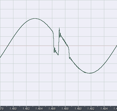
Not all of the pops are just two UDP packets processed in reversed
order. Many of the pops actually involve three UDP packets,
moving one forward in time by two slots! These two screenshots show
such cases. The UDP packet containing the data samples
corresponding to the approach to the negative peak of the beat note was
moved two slots left, then come the two UDP packets that were
skipped, and then the data flow continues normally. The same kind of
out-of-queue processing happened in the sample at right, only at a
different place of the waveform.
It's important to stress that no data seems to be lost. It's just
swapped out of sequence, not dropped nor repeated. After each pop the
sine wave continues without any phase shift.
Then I captured a few seconds worth of UDP packets, using Wireshark,
and looked at them. I spent a good while searching for any packets with
their serial numbers out of proper sequence, but couldn't find any. The
UDP traffic seems correct, as far as I can tell. What I might still do
is a write a small program to analyze the actual sample data, and see
if the Red Pitaya is sending packets with correct serial numbers but
swapped content. But this seems futile, given that the amount of
popping I get is strongly dependent on other programs running on the
PC, and on PowerSDR's setup, while the RP keeps operating exactly the
same way.
So my conclusion is that this problem is internal to PowerSDR, perhaps
triggered by other programs on the PC also requesting DPCs (deferred
procedure calls), and is not a problem of Pavel's RP software nor
of the UDP data flow between the RP and the PC. According to reports
from other people, using an extremely powerful PC seems to reduce the
problem to a level where it's not easily noticed in practical
operation, but there is a real bug that needs to be fixed.
Update, again! (2017-6-30):
I analyzed the UDP data, and it looks correct. So the facts are: The
Red Pitaya with Pavel's software is sending the correct data, my PC is
correctly receiving the data, and PowerSDR is changing the order
of UDP packets. How often this happens depends on CPU load, so that
when shutting down my firewall and NTP programs, and when configuring
PowerSDR to cause a lighter CPU load, I get far fewer of these
events - but I still get them, even at a total CPU load well below 10%!
They keep happening at a rate of ten to twenty pops per minute.
I can see that if any of my drivers (BIOS and otherwise) causes long
delays through poorly implemented interrupts and DPCs, the SDR software
might not be able to cope, due to an excessively small buffer, and
start stuttering. But I cannot see why it should switch the position of
UDP packets!!! This MUST be a bug.
 While
playing with everything set up for least popping (disconnected from the
internet, firewall off, NTP off, all non-essential Windows services
turned off, PowerSDR configured for low CPU load) it became very
obvious that I have two different kinds of popping: One is the UDP
packet position switching detailed above, and the other is simply
audio dropouts. The audio signal goes to zero, and after 2.667ms
resumes at the same position of the waveform where it stopped. There is
no filter ringing on these dropouts, showing that these happen in the
audio stream, not in the input data stream. A simple calculation
confirms this: 2.667ms contain 128 samples at 48kHz, and I had the
audio buffer size in PowerSDR set to 128. Changing it to 256 doubled
the duration of each dropout, and halved the frequency at which they
occur, from about 35 seconds between dropouts to about 70 seconds.
While
playing with everything set up for least popping (disconnected from the
internet, firewall off, NTP off, all non-essential Windows services
turned off, PowerSDR configured for low CPU load) it became very
obvious that I have two different kinds of popping: One is the UDP
packet position switching detailed above, and the other is simply
audio dropouts. The audio signal goes to zero, and after 2.667ms
resumes at the same position of the waveform where it stopped. There is
no filter ringing on these dropouts, showing that these happen in the
audio stream, not in the input data stream. A simple calculation
confirms this: 2.667ms contain 128 samples at 48kHz, and I had the
audio buffer size in PowerSDR set to 128. Changing it to 256 doubled
the duration of each dropout, and halved the frequency at which they
occur, from about 35 seconds between dropouts to about 70 seconds.
These dropouts are surely caused by mismatch between the clocks of the
Red Pitaya and the sound card. Due to the finite accuracy of quartz
crystals, 48kHz derived from the Red Pitaya's crystal, and 48kHz
derived from the sound card's crystal are two slightly different
frequencies. These numbers also allow to compute the mismatch between
the Red
Pitaya's and the sound card's clocks: A whopping 46 ppm! Most of this
must be the sound card. Otherwise the frequency calibration in
PowerSDR
would show it.
A good DSP program should handle this inevitable fact of life, by doing
a variable rate resampling or some other software trick, but PowerSDR
so far doesn't. If at least the program would skip or interpolate
single samples as needed, the resulting very minor clicks and
distortion would probably be small enough to go unnoticed. But zeroing
out an entire data buffer, with 128 or more samples, is pretty much the
worst possible way to handle a clock mismatch!
My appeal goes to the good people working on PowerSDR. They do it for
free, so neither I nor anybody has a right to firmly request a fix. But
I would still ask them to please look into both of these issues, if
possible. No matter how many great features PowerSDR has, it's not
really acceptable for daily use as long as it contains fundamental
flaws like these! Using a super fast, dedicated PC to get around
the UDP packet swapping problem, as often suggested, is an expensive
bandaid for an existing software bug, and doesn't do anything
about the clock mismatch problem.
I just fired up HDSDR again - it produces no popping whatsoever, even
when running it at over three times the maximum sampling rate PowerSDR
is capable of, and with the firewall and all other software enabled,
running a web browser at the same time, and several other programs.
This shows that there is no fundamental reason why we should live with
popping, nor need SDR-dedicated PCs! The popping of PowerSDR is caused by (at least) two software
bugs, and these should be fixed.
Being a BASIC hobby programmer myself, I strongly hesitate to even try
finding the bugs myself, in PowerSDR's extensive C source code. It
should be much easier for the people who have been working on that
software. But the bugs are probably buried deep inside, possibly even in libraries used by the program. A
web search shows that users have been complaining for many years
about the popping, even on the Flexradio website, and nobody fixed the
bugs.
For the time being, the popping continues, and is a serious problem
that's making me reconsider whether it makes sense to build an SDR
around
this platform. I don't want to build a radio that sounds like
a
Geiger counter!!! Yes, I know what some people will suggest:
"Forget SDRs, and keep using your Kenwood!" I prefer looking
forward. The PowerSDR bugs have to be fixed!
And yet another update (2017-8-24)
Warren, NR0V, undertook improving PowerSDR to fix the popping.
Systematic testing showed that the problem of out-of-order UDP packets
isn't happening inside PowerSDR, but in Winsock2. That's the Microsoft
library that's used by Windows programs like PowerSDR to communicate
through the ethernet. The UDP packets were arriving in proper order in
my PC, but PowerSDR was sometimes getting them out of order. While it's
not nice that Winsock2 does this, one cannot really say that it's a
bug, because by the definition of the UDP protocol, packets are not
guaranteed to arrive in proper order! So Warren put some new code into
PowerSDR that re-orders such out-of-order packets, and this fixed the
problem that was causing the most pops! And since then he has been
working on solving the audio dropouts caused by lack of synchronization
between the acquisition clock and the soundcard clock. It looks like in
some more time PowerSDR will be completely free from popping even those
PCs having less than stellar performance.
Transmitting:
 Of the Red Pitaya's two RF outputs, only one is currently used by
Pavel's software. This provides the transmit signal, at a level
adjustable up to ±1V into a 50Ω load, which equals a power level of
10mW (+10dBm). Basically this signal has to be amplified by about 40 to
52dB, in a linear way, to be put on the air.
Of the Red Pitaya's two RF outputs, only one is currently used by
Pavel's software. This provides the transmit signal, at a level
adjustable up to ±1V into a 50Ω load, which equals a power level of
10mW (+10dBm). Basically this signal has to be amplified by about 40 to
52dB, in a linear way, to be put on the air.
The RP's outputs are intended to be loaded by 50Ω, but they do not have
an internal 50Ω source resistance. To obtain the correct response from
the built-in 50MHz low-pass filters, it's important to load the outputs
with 50Ω. I built a simple and totally conventional class A amplifier
stage around an antique but good 2N5109 transistor, which was on hand,
just to act as a clean buffer stage and isolate any of my possible
mistakes from the expensive RP. This amplifier uses both emitter
degeneration and collector-to-base feedback. I can configure it for
gain levels of 10 to 15dB, by changing two resistors. 15dB gain means
316mW output power, and is about the upper limit for a transistor
running class A and dissipating 1W. Any higher power makes it clip the
signal and produce undue distortion. A gain level of 12dB results in an
ultra clean amplifier, that has the third order IMD products well below
-50dB.
I placed an order for some RD06 and RD16 MOSFETs, which seem to be the most
convenient devices currently available for HF amplification at
levels up to 20W or so, and my intention is to use these for an
amplifier that drives my big, fancy, high efficiency, high power final
stage. It's two months since I ordered these transistors, and they
still haven't arrived, thanks to ever-increasing delays at Chilean
customs. Oh well.
Update! The MOSFET drive amplifier (2017-6-20):
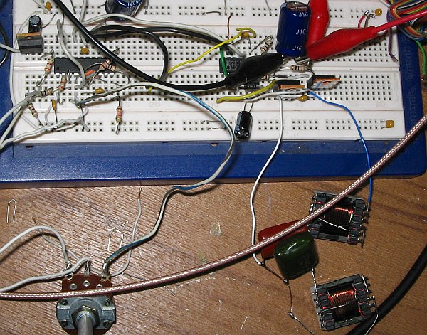
 After
a looooong wait, finally the MOSFETs arrived, and I built a simple
two-stage driver amplifier, using a single RD06HHF1 as class-A driver,
and two RD16HHF1 in push-pull class AB.
After
a looooong wait, finally the MOSFETs arrived, and I built a simple
two-stage driver amplifier, using a single RD06HHF1 as class-A driver,
and two RD16HHF1 in push-pull class AB.
The RD06HHF1 isn't really well suited for this driver stage. The Red
Pitaya delivers just 10mW, and this first stage is supposed to amplify
this to roughly 400mW. But the transfer curve of the RD06 begins
to get reasonably linear only at roughly 0.5A! So, at 12V, one needs to
run this stage at 6W input power, to get a reasonably symmetrical
output waveform. This makes for an efficiency of less than 7%! A
smaller MOSFET should have been better for this stage. But which? There
are some SMD ones, but for quick experimentation these aren't as
convenient as a good old TO-220.
When running this stage at lower current, the gain drops somewhat but
is still pretty good, while the symmetry of the output signal becomes
horrible. Interestingly the impact of this on the IMD is small. An
asymmetric waveform implies the presence of strong even-order
distortion products, while close-in IMD is purely odd-order. The most
obvious spectral effect of the asymmetry is instead a very strong
second harmonic. And the most prominent problem caused by signal
asymmetry is very unbalanced driving of the push-pull stage following
this one! One FET works much harder than the other, and there is a
significant DC component in the output transformer. For these reasons
I'm running the RD06 at 0.5A for now, achieving a symmetric-looking
waveform and better than -50dBc IMD, but for any definitive
implementation I would consider using the 2N5109 instead, or two of
them in push-pull. It's very linear at much lower current, and thus far
more efficient at a given level of gain and linearity.
I designed input and feedback networks that compensate for
the RD06's input capacitance and for its frequency response. The result
is an stage that has 16dB gain, very flat from 1.8 to 30MHz, and an
equally flat 50Ω input impedance. This is important, because the Red
Pitaya has a 50MHz low-pass filter on each of its RF outputs, and these
need to be loaded with 50Ω to deliver their correct frequency response.
The RD16HHF1 FETs were a rather nasty surprise. I had taken the
manufacturer's specs of "16 watts output per device at 55% efficiency,
at 30MHz, minimum, and 19W at 65% typical" at face value. But these
FETs just don't deliver that! Their RDSon is so high that at a nominal
12.5V supply voltage the rated minimum output of 16W is the absolute
maximum value, when the FET is running fully saturated, with a
square wave on its drain! Under these conditions the drain-source
stauration voltage is around 5V, which is sky-high for a 12.5V FET, and
the efficiency is scratching the 50% mark. In linear service
the best I could make them deliver is roughly 12W for a pair (just 6W
each!) at about 50% efficiency. Loading them at a lower impedance they
will do just a few more watts, at drastically lower efficiency. I got
17W for a pair, at 38% efficiency, and -26dB IMD.
So I had to change my goals, to meet these FETs' real capabilities.
Originally I hoped to get 25W in linear operation from the pair, at no
worse than 50% efficiency. After realizing that these FETs can't do it,
or at least not at 12-13.8V supply voltage, and changing my output
transformer accordingly, I'm getting 10-12W linear output, depending on
the band, at the drive level that gives an IMD3 of -30dB referred
to each tone, for the complete amplifier.
This isn't the definitive version yet, and that's why I'm not posting
the schematic right now. I intend to use this as a driver for the
development of a high efficiency, high power final stage, and I
don't know yet what the real drive requirements for this stage will be.
So my plan is to work on that final stage first, using this drive
amplifier as it is now, and then determine the specs for the definitive
driver amp.
And maybe - just maybe - the definitive one might even be built on a printed circuit board! :-)
No EER support!!!
While I wait for those FETs, and with the little class A
buffer amplifier in place, I started doing the preliminary
tests
for my intended high efficiency, predistortion-corrected amplifier. The
first big and nasty surprise was that Pavel's HPSDR-compatible software
for
the RP does not support PowerSDR's EER transmission features at all!
This is really a very big downer. Sure, I can still make an
EER
amplifier by using a conventional hardware-implemented envelope
detector, but it's pretty much impossible to implement the required
delay of the phase drive signal in hardware. PowerSDR implements it in
software, but that's inaccessible because of lack of an envelope signal
output in the RP
software! This is a double shame, because the RP is ideally suited to
EER, actually better than the Hermes, thanks to having two high speed
analog
outputs, compared to the Hermes' single one. It should be comparatively
simple to add envelope output via the second DAC channel!
So, it looks like I will
only be able to implement a much lower quality EER system than would have
been possible through the use of the EER functionality provided by
PowerSDR, and it will be slightly more complex to implement.
In fact I purchased the RP mainly because I thought it would allow me
to make an EER transmitter having the proper time alignment between
envelope and phase! And then I found out that the only software
available for the RP does no support this...
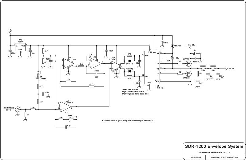
Update! (2017-8-24):
Pavel now implemented EER on the Red Pitaya, by sending out the
envelope waveform on Output 2! Since then I'm building what's
necessary on the hardware side to run EER. I'm using an UC3638 motor
control IC as the pulse width modulator with dead-time control,
followed by an IR2110 high/low side MOSFET driver, and for now just a
pair of IRF530 MOSFETs in class D to modulate the 13.8V supply to my
test amplifier, through a 25kHz lowpass filter.
Predistortion:
PowerSDR includes an adaptive phase and amplitude predistortion system,
called "PureSignal", that can correct nonlinearities of the power
amplifier chain. And Pavel's software fully supports this on the RP. I
installed the required RF feedback from my little test amplifier's
output to the #2 input of the RP, and started testing. There
are
some good and some bad news. The good are that the system easily
improved my amplifier's already very good -50dB IMD figure to
a
whopping -70dB, and at some times even -80dB.
The first bad news is that the results are a bit erratic, apparently
caused by the popping problem described above, and possibly also by
some
other software bugs. For example, the phase and gain diagram generated by the
system is sometimes very reasonable, and at other times it's totally
absurd, without me changing anything in the settings nor the hardware.
This needs some more investigation. Maybe the problem will go away if
the popping problem is solved - if that ever
happens.
And more bad news showed up when I tried to intentionally degrade the
linearity of my test amplifier, by running it into mild saturation, or
biasing it too low. When I did that, PureSignal didn't work at all! The
signal remained uncorrected, as bad as with PureSignal
deactivated! So it seems that PureSignal can make a good signal
excellent, but it cannot make a poor signal good. And that's very bad
news for me, since I hoped to build an EER amplifier, which inevitable
is quite poor in terms of amplitude and phase linearity, and correct it
through predistortion so as to obtain a decent quality signal.
I need to do more experiments with PureSignal, but the popping problem must be solved first.
Update! (2017-8-24):
Talking over with Warren the erratic behaviour of PureSignal on the Red
Pitaya, it turned out that it was mainly due to the signal level
produced by the RP on RX3. PureSignal requires a specific signal level.
Pavel fixed this in his software, and now PureSignal works very well!!!
The only important limitation I still see with PureSignal is the
limited correction bandwidth. While it can reduce all spurs within
±20kHz to negligible levels, even for pretty crummy amplifiers,
it cannot do anything about spurs lying outside that range. So whatever
amplifier one uses needs to be clean enough to have all high-order IMD
products and spurs sufficiently well attenuated, pretty much regardless
of how dirty it is close-in. And then PureSignal can be used to
dramatically improve the signal purity inside its ±20kHz correction
range.
This allows obtaining very good signal quality even from strongly
overdriven amplifiers, while underbiased amplifiers end up producing a
larger amount of far-out IMD, limiting how low one can set the bias
before this IMD becomes a practical problem. Anyway, even with almost
no idling current, the uncorrected far-out IMD is suppressed at least
50dB, and typically more, so it might be considered acceptable.
It will be interesting to see how well an EER output stage fares with PureSignal!
Is there any point in continuing this project at all?
This sounds a little harsh, but it's a question inevitably going 'round
in my head. My core interest in building an SDR was implementing a
pretty good high
power EER amplifier, using PowerSDR's EER capabilities, and then
correct the remaining distortion through PowerSDR's adaptive
predistortion. So, basically I wanted the Red Pitaya as a system
to properly drive and bend straight a big EER amplifier, having the
typical SDR advantages for receiving thrown in as a bonus. And
the reality I
see now is that because of lack of EER support in the RP software I
can't use the EER features of PowerSDR at all, limiting me to a rather
poor
EER implementation without the required delay of the phase signal, and
then I won't be able
to correct it at all through adaptive predistortion! That's just as bad
as driving an EER amplifier from an old technology, analog exciter! It
simply crashes my project! And the bonus SDR receiver keeps
popping like a Geiger counter...
Sure, I could instead build a totally conventional class AB power
amplifier chain that has good enough linearity, and just live with the
popping. But instead of doing that, I could as well keep using my old
TS-450 transceiver and NCL-2000 linear amplifier! This whole SDR project isn't attractive to me if
the
high efficiency, high power transmitter producing a decent quality signal can't be implemented.
I even toyed with the idea of trying to get into the source code of both PowerSDR and Pavel's RP program, to try
and fix the popping, and to implement EER functionality in the RP. But that
seems awfully difficult to a 52 years old electronician, who
is fluent neither with Linux nor with C nor with FPGA programming, and
whose programming experience is mostly in BASIC, Assembly,
microcontrollers and computers running relatively simple operating
systems. It seems far more likely that I will have to wait, and cross
my fingers that the authors of this software will keep improving the
programs so that it will work perfectly and do all the things I need.
In the meantime, it's fun to play with SDR and learn.
And an update to this, too! (2017-8-24):
Thanks to the help of Warren and Pavel, improving the software, it now
does make sense to go forward and try building my high power, high
efficiency SDR transceiver. So I have ordered an MRF1K50N and the
lot of other parts required, and until everything arrives I will be
experimenting with EER using my small RD16 drive amplifier as a guinea
pig. I don't know yet what exact flavor of EER, H-EER, ET, etc, will
work out best, and I only have some unproven ideas about how to make a
bandswitched high efficiency final stage. They will have to be tried
and tested. Pure EER is still not possible with the existing software
combination, specially in combination with predistortion, but ET should
work.
ET test successful!! (2017-8-26)
 The
Envelope Tracking test setup described above was completed and tested.
Since I built it on a protoboard, there is some interference from the
switching power stage into the pulse width modulator, causing some
distortion on the amplified envelope signal, plainly visible on a
scope. Even so, the resulting RF output signal is surprisingly good -
and can only get better if the PWM is properly built!
The
Envelope Tracking test setup described above was completed and tested.
Since I built it on a protoboard, there is some interference from the
switching power stage into the pulse width modulator, causing some
distortion on the amplified envelope signal, plainly visible on a
scope. Even so, the resulting RF output signal is surprisingly good -
and can only get better if the PWM is properly built!
The spectrum shown here depicts the RF output obtained, with over
300kHz bandwidth to allow seeing the most important things. The IMD3 is
40dB down - that's significantly better than what I obtained from this
amplifier in class AB "linear" operation!
All amplifiers powered by a switching circuit (switchmode power supply,
or as in this case a switchmode modulator) will produce sidebands
separated from the main signal by the switching frequency and its
multiples. That's why I used such a wide setting for the spectrum
analyzer, so that the first (and strongest) of these sidebands is
shown. Its peak is 60dB below the main signal, which should be
acceptable. In any case, if so desired it can be further attenuated by
increasing the order of the lowpass filter used between the modulator
and the final stage.
And this is the RF output spectrum with an actual voice signal.
It's almost funny to see how efficient such an amplifier is! Just to
fool around, I lifted the RD16 FETs from the heatsink and ran them in
free air. At 12W PEP output, continuous duty with the two-tone signal,
they got warm but not hot. On the heatsink, of course, everything stays
stone cold.
The modulating IRF530 FETs weren't even mounted on a heatsink. They
stay cold too, in free air. I love EER and ET! At the 12W
level it's just a game, but later at the kilowatt+ level this will be
important.
Who said that 200kHz switchmode power amplifiers cannot be built on a protoboard?
A better PWM (2017-12-20)
After playing for some time with the UC3638-based PWM, it became clear
that this motor controller IC has some shortcomings when used as class
D amplifier controller for the widest possible range of pulse width.
Specially the rather large hysteresis of its comparator makes the
pulses snap to zero or 100% duty cycle rather early on the
transfer curve. Since this behaviour cannot be changed from the outside
of the chip, I decided to scrap the beautifully simple UC3638 circuit
in favor of a more conventional but also more complex solution using
opamps and comparators.
This design uses fast comparators with rail-to-rail complementary
outputs, and fast, low distortion, low noise opamps. It works
significally cleaner than the UC3638, and is fully controllable by the
designer/builder, but is still not able to work cleanly from zero to
100% duty cycle, due to comparator hysteresis. A few percent of the
range have to be sacrificed at each end. Another version using much
slower, antique LM311 comparators with pull-up resistors and a MOSFET
inverter produced less clean internal waveforms, but still produced
almost the same quality in the final signal. So if you don't want to
solder the ant-size LT1713, feel free to go the LM311 route.
Note that this circuit is not final!
It's intended just for experimenting at low power. The final version
will use several MOSFETs of a more modern type in parallel, probably
with a stronger driver, and might not have the deadtime circuit shown
here between U3 and U5, or might have it but with a different time
constant. Actually I built my test circuit without the deadtime
circuit, but included it in the schematic for completeness. Also the
startup behaviour of this circuit is still uncontrolled, which I intend
to revise for the final version. But if you want to experiment with EER
or ET, this circuit should do quite well.
Just in case you haven't noticed: You can click the schematic to get a legible version...
Defining the project
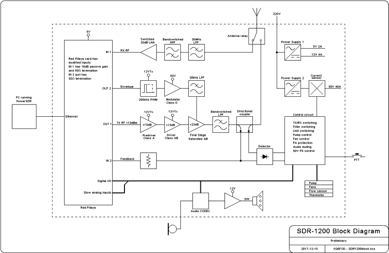
These days I have been in a mood to make handsome drawings, so I
drew a basic block diagram of my intended transceiver too, as things
stand right now. A lot of this remains to be defined, changed,
experimented, dropped, replaced, given up, reinstated, and so on.
Even so, this block diagram might be useful to make clear what I'm trying to develop...
Trying other pulse width modulators (2018-3-10)
I'm not completely satisfied with the performance I'm getting from my
pulse width modulator. So I tested some options. Below are a few
oscillograms that allow comparing the linearity of different
approaches. You can click these oscillograms to get larger and more
detailed versions. Each of these was done by applying a 100Hz triangle
wave, adjusted to slightly saturate the PWM, so that the flat extremes
of the curves represent zero and 100% pulse widths. Then I adjusted the
scope to make best use of its screen.
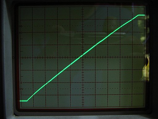
I was given two samples of the LTC6992-1. That's a tiny 6-pin SMD that
implements a complete, full range pulse width modulator, requiring only
an extremely simple external circuit, and accepting a 0-1V input range.
At first sight it seems ideally suited to the task of turning the RP's
analog envelope signal into a PWM signal.
I made a basic test circuit configuring the IC's oscillator for 200kHz,
its internal frequency divider to 1, and passing the PWM output through
a 2-pole RC lowpass filter with a cutoff frequency of around 20kHz.
Unfortunately the catch lies in the poor linearity this IC has. The
oscillogram shows a very clear bow in the overall curve, deviating up
to about 4% from the straight line. Also the line is somewhat wavy
instead of straight, as if the PWM function was implemented in many
small sections spliced together.
The upper end of the response shows a clean transition to 100% pulse
width, with is excellent, but the lower end shows a slight step
response - the IC cannot produce arbitrarily short pulses, dropping
instead to zero pulse width below a certain threshold.
Looking at the output pulses one can see a severe frequency pulling
effect during modulation, which might be involved in the overall bowing
of the tranfer function.
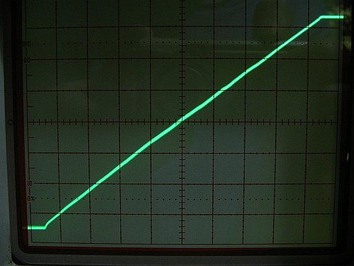
There are two ways to run this IC at 200kHz. The one recommended in the
datasheet, for reasons of lower power consumption, is the one measured
above. The alternative is to configure the oscillator for 800kHz, and
set the frequency divider to 4. This is what I did next.
Interestingly the overall linearity is much better in this
configuration, with the overall distortion being only about half as
much. But the waviness of the response remains, perhaps even stronger
than before, the distortion at the low end increases, and some
distortion appears also at the high end.
I cannot blame this IC, which was never intended for high quality, low
distortion pulse width modulation, but for simple non-demanding
application such as display backlight control... It has a linearity
specification of 4.5%, and it does meet it. But this just isn't
good enough for the task at hand. And that's a pity, because it looked
sooooo attractive, with its extremely simple application circuit!
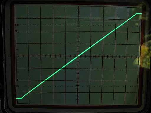
So I'm back to the circuit shown a bit up in this page, built around
two LT1713 comparators and an LM4562 op amp. This oscillogram shows its
output, using the same 2-pole RC filter used for the oscillograms
above. But it's powered from 5V, instead of the 8V shown in the
diagram, which puts the LM4562 in a rather compromised situation, given
that it's not a rail-to-rail opamp, and not even a single-supply op amp.
Still the overall linearity of this circuits is very much better than
that of the LTC6992, appearing to be essentially a perfect straight
line from about 3% to 96% pulse width. But the ends of the range do
show distortion. Closer inspection with the scope shows this to come in
part from the switching transients of the second comparator causing
interference to the op amp and first comparator, while another thing
contributing to distortion is the lack of speed of the LM4562. That''s
a pretty fast and very good op amp, but to make a really clean 200kHz
triangle wave, even higher speed would be better. So I have ordered a
few LT1809, which are very fast rail-to-rail op amps. In about 4
months, the time typically taken by the Chilean postal service to
deliver a parcel, I hope to be able to continue improving my PWM...
The ridiculous slowness of the Chilean postal service is a disgrace.
They claim it's the customs processing that causes these delays, but a
simple letter sent to me by priority airmail from Germany took the same
4 months to arrive, and I don't suppose that letters are subject to
customs processing...
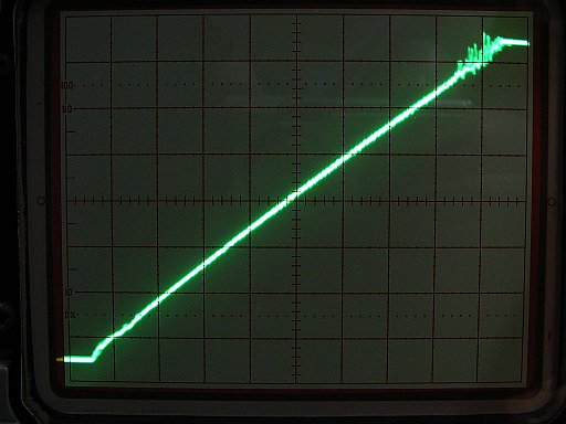
This shows the output of the power stage shown in the diagram above,
using an IRS2110 driver IC, two IRF530 MOSFETs, the 4-pole LC low-pass
filter, and a 10Ω load resistor. The power supply was 13V with somewhat
weak stiffness (long cable), and the PWM circuit is the one of the
previous oscillogram.
The first obvious feature is quite some interference from the power
switching into the PWM. I have to say at this place that the circuit is
still built on a solderless protoboard, so this kind of problem is to
be expected! It should largely go away when making a good PCB.
However the poor construction on a protoboard is a great tool to
uncover other problems! The large switching chaos in the upper 10% of
the range is caused by shoot-through in the power MOSFETs, causing
intense current pulses of a few nanoseconds duration, that cause
increased interference to the PWM.
The IRS2110 has pretty good pulse width fidelity when the pulses aren't
too short. But when input pulses get narrow, or near 100% wide, this IC
increasingly alters their widths - and when driving the two inputs with
exactly complementary signals, as my LT1713 is doing, the IRS2110
actually drives both MOSFETs on at the same time, for brief moments!
So it would have to be used with a deadtime circuit. That circuit is
shown in the diagram up this page, but was NOT in place when taking
this oscillogram.
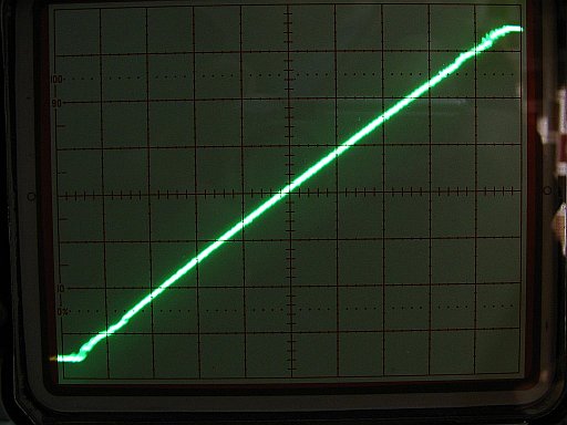
Instead of inserting that deadtime circuit, I replaced that chip by an
IR2110. The IRS2110 and the IR2110 are extremely similar and
pin-compatible, but the version without the "S" has a
significantly longer delay for switch-on than for switch-off of each
driver output. As a result it provides a deadtime by its own, when both
inputs are driven with exactly complementary waveforms.
The effect of the change is obvious: The interference to the PWM
circuit is much reduced, because the large shoot-through pulses are
gone.
Unfortunately there is some waviness in the response, affecting roughly
the first and last 15% of the range. Some of this is caused by the
construction on a protoboard, but also some is caused by the driver
chip proper, which does change the pulse widths to different extents
depending on the input pulse width. Also the deadtime it enforces tends
to be a little too long, like 40ns, and class D amplifiers depend on
near-zero deadtime to maintain a linear response.
What I take away from these tests is:
- The PWM circuit with fast comparators and op amps is best;
- A faster op amp there should help, specially a rail-to-rail one that allows a larger signal swing;
- Good layout on a PCB should contribute to making that PWM circuit plenty good enough;
- The LTC6992 instead is unfit for this application, and so are the
other ICs I tried before (power supply and motor controllers);
- A faster/better driver with the best possible pulse width fidelity is needed in the power stage;
- PCB layout of the power section must be top notch, when the circuit will handle 50V 40A instead of the experimental 13V 1.5A.
More news related to the above
Pavel might program a pulse width modulator into the RP's FPGA. This
would delete the necessity for a hardware PWM. But he sees trouble in
achieving a high enough PWM frequency along with sufficient resolution.
He mentioned using sigma-delta modulation instead of PWM, which he says
is easier to implement with the required quality. The problem I see
with that is decreased modulator efficiency, due to the higher number
of switching transitions per unit of time, causing higher switching
loss. Maybe it would be best to use a sigma-delta system with the data
stream processed in such a way that pulses are transposed and joined,
aways keeping the number of transitions per time unit below a certain
limit.
A nice byproduct of using delta-sigma modulation would be that the
humps of spurious signals 200kHz away from the main signal should go
away, replaced by more broadband, lower level artifacts, which are less
likely to be detectable.
I'm wide open to experiment, and finally use what works best.
After a long time, some life signs... (2021-1-5)
It's almost 3 years since I last updated this page! And that's because
really not very much has happened. Given the current state of ham
radio, with very little interesting (to me) activity on the bands, my
motivation level has been low, and so I have built several other
projects, rather than spending a lot of time on my SDR project.
So, here are the news of what little this project has advanced in these 3 years.
The (hopefully) definitive modulator:
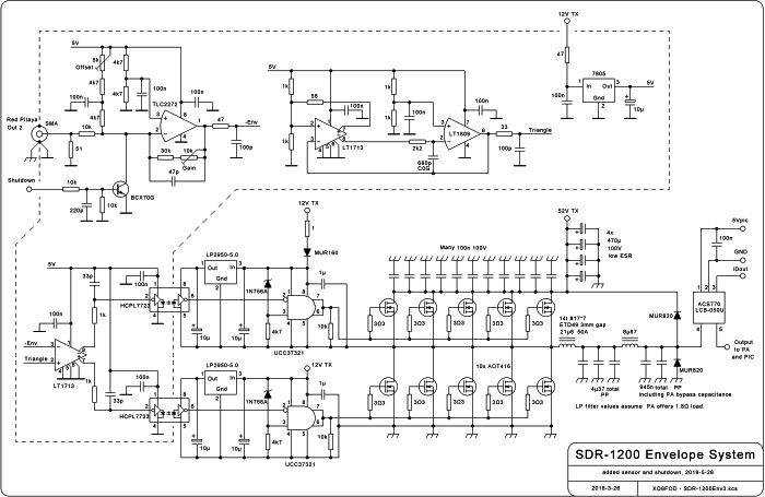 The
input section, using one side of a TLS2272 op amp simply because I have
a bag of them in SMD format, takes the 0-1V envelope signal from the
Red Pitaya, and amplifies it with adjustable gain and offset to the
level required by the pulse width modulator. A transistor is used to
shut down the modulator by pulling down the input signal, for example
when high SWR is detected.
The
input section, using one side of a TLS2272 op amp simply because I have
a bag of them in SMD format, takes the 0-1V envelope signal from the
Red Pitaya, and amplifies it with adjustable gain and offset to the
level required by the pulse width modulator. A transistor is used to
shut down the modulator by pulling down the input signal, for example
when high SWR is detected.
The triangle-wave oscillator uses the same design as already shown
above, based on an LT1713 comparator but using an LT1809 op amp, as
suggested in the comparator's datasheet. It has a cleaner performance.
The pulse width modulator is simply another LT1713 in the most basic
configuration possible, but the deadtime control has been done in an
elegant and hidden way: The HCPL7723 optocouplers have TTL-compatible
inputs, so their threshold is around 1.4V or so, while the comparator
outputs switch between 0 and 5V. Using a simple RC delay network
between each comparator output and its optocoupler input, this
asymmetry makes the delay of the upgoing transition shorter than that
of the downgoing one. And since these optocouplers have inverting
inputs, logic 1 means optocoupler is off, MOSFET is off, and as a
result there is a small deadtime, controllable by the values of the 1kΩ
and 33pF components. The high-side and low-side switches could even use
different delay values, if this was required to equalize the dead times.
Instead of the IR2110 of the test circuit, I used optoinsulated
signal coupling, followed by high-current MOSFET driver chips. This
results in very much more precise and well-aligned switching
transitions, also faster switching, lower loss, and ultimately lower
distortion of the modulator's output. I chose the UCC37321
drivers because they have an enable input, which comes in very handy to
implement an undervoltage shutdown, required to prevent MOSFET failure
in the event of a brown-out of the 12V supply while the 50V supply
still works. The whole driver circuit is made even more complex by the
optocouplers' need for a regulated 5V supply, while the drivers run
from 12V to produce appropriate MOSFET gate drive. This required adding
a micropower 5V regulator in each driver block.
Despite the fact that the input circuitry and the power stage are
referenced to the same ground, the physical construction should have
the whole low power circuitry on a separate ground island, joined to
the main ground only at the input connector. This eliminates ground
loop trouble. The 12V input to the regulator powering the small-signal
circuitry goes through a resistor, for the same reason. It keeps the
small-signal ground free from noise generated by the power section. The
dashed line in the schematic envolves all the parts that end up on the
single-point-grounded island.
Using an optocoupler not only for the high side, but also for the low
side, was necessary not only for this ground loop prevention,
but also to keep the two drive signals well aligned in time. The
selected optocouplers have very tight timing tolerances.
The resulting total drive circuit is far more complex than using an IR2110, but its performance is also very much better.
The high-side driver is powered from a bootstrap system. For this
reason the modulator cannot be used at 100% duty cycle for transmitting
a long carrier. But the 10µF capacitors allow enough autonomy to
get over SSB peaks, so it is possible to get 100% duty cycle in
SSB. On the other hand, this should be avoided in the interest of
linearity, since the system becomes non-linear in the last few percent
of its range. It's better to choose the supply voltage high enough, a
few volt higher than what the RF power amplifier needs, and align the
input signal conditioner so as to limit the duty cycle and thus the
peak output voltage to the desired values.
The power stage uses 5 MOSFETs in parallel in each block. The low side
is identical to the high side, despite running at much lower average
current. I would like to stress that using 5 transistors in parallel
was not done to handle the
current, but to get low enough lead inductance and thus achieve
clean-enough switching! And the peak current that has to be switched is
exactly the same for the high side and low side, which explains using
the same number of transistors in both blocks.
Since this modulator uses no negative feedback, it is essential to
achieve clean switching, sharp turn-on and turn-off, absolutely minimal
deadtime, and good saturation, if we want to get a low-distortion
envelope signal!
The AOT416 MOSFETs used in this design are fast, have a low gate
charge, have enough headroom for significantly higher supply voltage
than 50V, and are also inexpensive.
The output low-pass filter is a 4-pole Chebyshev design, optimized for
the load resistance offered by an RF power amplifer using 1:9 impedance
matching. The capacitors are low-loss polypropylene types, while the
inductors were wound on airgapped ferrite E cores with round center
legs. Most or all of the output capacitance of this filter is actually
the RF bypass capacitance in the RF power amplifier.
Two fast rectifier diodes are included to clip any overshoot or
understood of the output. Also a fast-responding Hall effect current
sensor is included on the board,
which can be used both for monitoring, protection and control purposes.
I built the circuit with a combination of protoboard and dead-bug
style, to test it. It seems fine, and should get better when cleanly
built on a PCB.
I started designing a two-layer PCB for this circuit, fitting on an
Eurocard, but repeatedly ran into trouble trying to achieve an optimal
design with low trace inductances where it matters, adequate thermal
layout, and without having to use any ugly jumpers. Maybe I set the bar
too high, but in several attempts I never finished that design. I
ordered all the missing parts from China, because it's the only country
from which sellers can still ship at a reasonable charge, but I got
some counterfeit parts along with some good ones. For example the
current sensor I got is an older, much worse, ±50A model, with its
printing sanded off and replaced by the printing of the part I
wanted... Such events don't help improve my already low
motivation to work on this project.
At least during these 3 years my understanding of RF power amplifiers
has kept improving. The bad news about this is that I have learned that
the saturated class AB stage, in other words a voltage-switching class
D stage, is impossible to achieve with LDMOSFETs running from 50V at
the kilowatt level over the whole HF spectrum. Very simply, existing
magnetic materials aren't good enough to implement the required drain
feed transformer (aka bifiliar choke) in such a small size that its
leakage inductance becomes sufficiently low. It can be done easily on
160 and 80m, it still works OK on 40m, it might be just acceptable on
20m, but definitely no higher. This forces a change in the
approach, toward a current-switching class D amplifier, because such a
circuit doesn't need a drain feed transformer. But the
current-switching class D amplifier needs a square wave drive signal,
that turns one transistor on before
turning the other off. More importantly, the resulting heavy cross
conduction (aka infinite idling current) that would result if there is
supply voltage while there is no drive signal would require designing
the modulator as a current source rather than a voltage source! And
this renders my modulator design obsolete before I even finished
designing a PCB for it...
So that's the state at the beginning of 2021: The modulator circuit
design is
done, the PCB design is only half done, and might need to be done
totally anew, parts have arrived but some are fakes and need to be
ordered again, and anyway the whole modulator concept might need to be
changed to current-mode. The 50V server power supply I bought ended up
being unusable for this project, because it has an incredibly noisy
fan, won't run without feedback from that fan, consumes about 200W when
idling (!), generates severe RF noise, and starts too slowly to be
switched off during RX. I need a better suited one, or build one.
Other hams have expressed very limited enthusiasm for
my project. It's actually hard to find any ham who even understands
its basic concepts! A larger number of hams tell me that I'm crazy (maybe they are right..), that it makes no
sense to design high-efficiency transmitting systems for hams, that
energy is cheap enough to waste some, and so on...
You might understand why my
motivation is a bit down, to put it mildly.
So I have instead built a drone. Also a conventional small 50W amplifier for the Red Pitaya,
to enjoy it on the air in some way at least. And several other small
projects not yet documented on my web site. In addition I have done some ferrite science,
and I'm currently writing a comprehensive article about RF power
amplifier design, but the EER project has been mostly resting,
waiting for a big injection of motivation.
Comments and questions are welcome. And any ideas to solve the problems
exposed here are particularly welcome! Collaboration is
invited.
You can contact me at  .
.
Back to homo ludens electronicus.


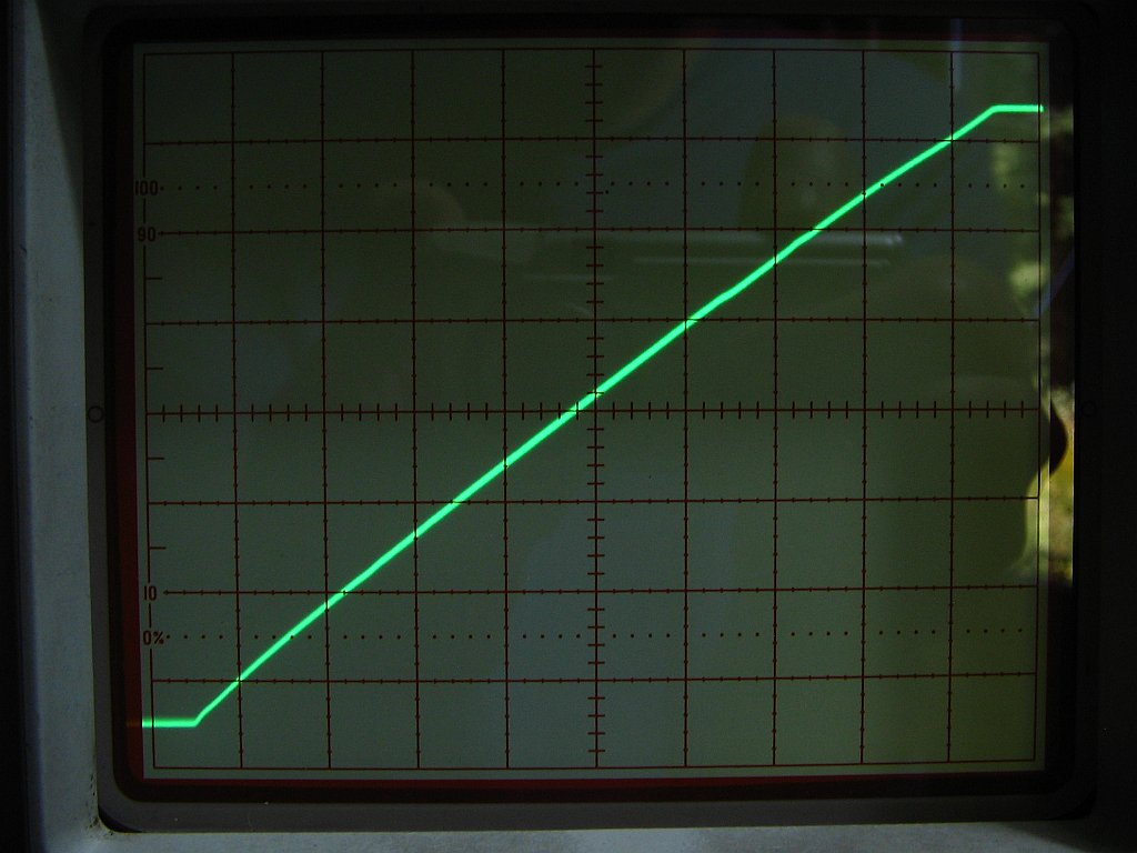


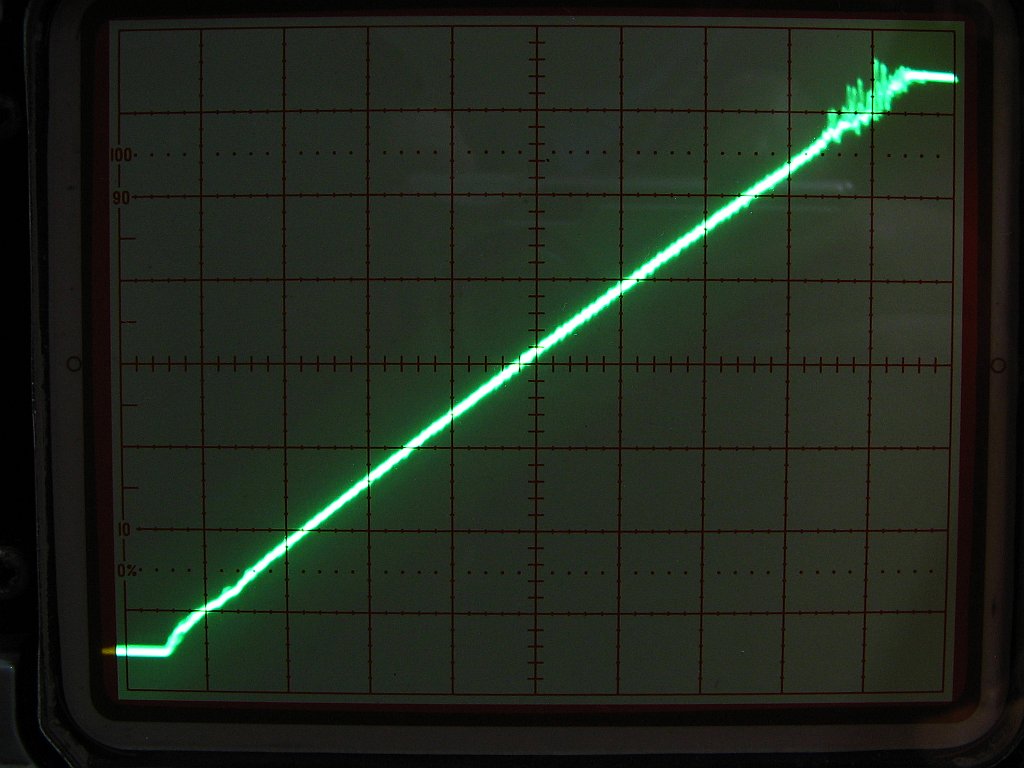

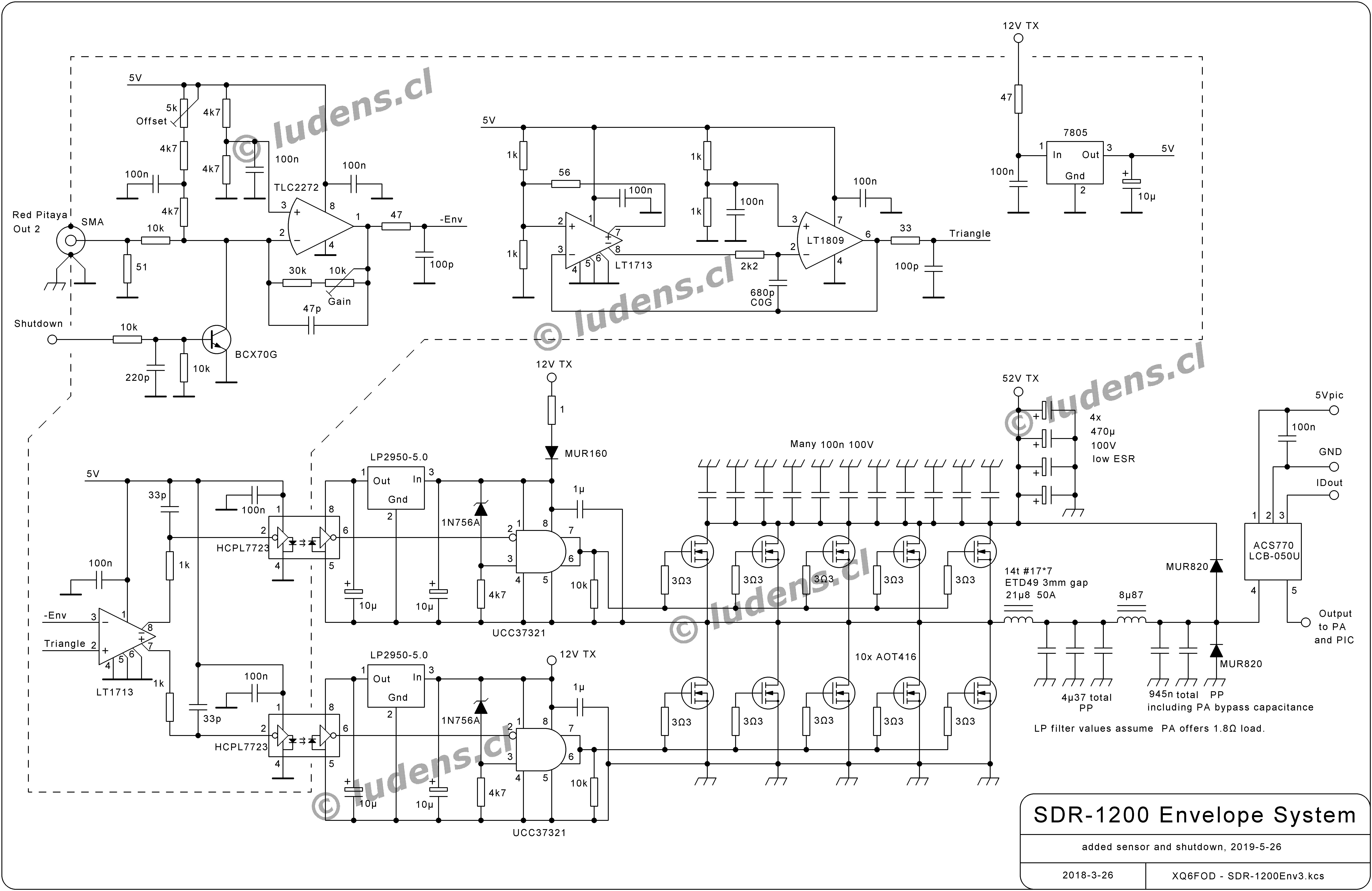 The
input section, using one side of a TLS2272 op amp simply because I have
a bag of them in SMD format, takes the 0-1V envelope signal from the
Red Pitaya, and amplifies it with adjustable gain and offset to the
level required by the pulse width modulator. A transistor is used to
shut down the modulator by pulling down the input signal, for example
when high SWR is detected.
The
input section, using one side of a TLS2272 op amp simply because I have
a bag of them in SMD format, takes the 0-1V envelope signal from the
Red Pitaya, and amplifies it with adjustable gain and offset to the
level required by the pulse width modulator. A transistor is used to
shut down the modulator by pulling down the input signal, for example
when high SWR is detected.