The antenna controller
In principle it would be perfectly possible to use this antenna simply
by installing a breakout box equipped to feed 6 Volt DC onto the coax cable,
with selectable polarity, and route this to some "Up" and "Down" manual
tuning buttons. These could then be used to manually tune the antenna from
inside the car, while watching a SWR meter, or even while listening. But
this is of course inconvenient, and even dangerous if done while driving.
So I built a fully automatic controller for my antenna.
Click on the schematic, or this link, to get it in full
resolution for printing.
The brain of this circuit is U3, a Basic Stamp II microcontroller. It
interfaces to the transceiver, getting commands and returning the proper
replies. It receives forward and reflected voltage samples, and has full
control over the DC-DC converter that powers the servo. It also gets input
from the motor current sensor.
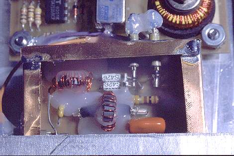
 The circuit inside the shield is the SWR sensor. T1 is a current mode transformer.
On its secondary side there is a sample of the current present on the coax
line, which is 1/22 of the line current. This current is applied to R1,
so that a voltage appears on it, which has a magnitude of 4.545 Volt for
each Ampere on the line.
The circuit inside the shield is the SWR sensor. T1 is a current mode transformer.
On its secondary side there is a sample of the current present on the coax
line, which is 1/22 of the line current. This current is applied to R1,
so that a voltage appears on it, which has a magnitude of 4.545 Volt for
each Ampere on the line.
T2 serves a double duty: One is feeding the switched 6VDC from the DC-DC
converter into the coax line. The other is providing two samples of the
voltage on the line, each of which is 1/11 of the line voltage, which also
is 4.545 Volt for the 50 Volt that should be on a 50 Ohm line when the
SWR is low and 1 Ampere of current is circulating. The two voltage samples
are combined with the current sample in such a way that one adds and the
other subtracts. The two combined samples are rectified by D3 and D4, and
RF-filtered, providing DC voltages proportional to forward and reflected
voltages on the line. This simple SWR sensor is quite accurate for
the frequency range needed here, provides sufficiently large sample voltages
for the 10 Watt power level used by most radios for tuning, and can pass
100 Watt of RF with only 0.5% loss, thus staying cool.
A reactance sensor would in principle be more useful than a SWR sensor,
since it could tell unambiguously to which side the antenna has to be tuned.
But such a sensor would have to be installed inside the antenna, because
of the impedance transformations performed by the impedance matching coil
and the unknown length of coax cable between the antenna and the controller.
That would require more wires running between the controller and the antenna.
For that reason I chose the SWR sensor, which works through any length
of coax. I solved the direction ambiguity problem in software.
The dual operational amplifier U1 is used to interface these sample
voltages to the Basic Stamp, which has no analog inputs. This is accomplished
by converting voltage to time: With an input voltage of 0 to 5 Volt to
R2, the transistor Q1 will conduct a controlled current of 0 to roughly
0.1mA. During rest time, C9 is kept discharged (both sides at 5 Volt) by
the Basic Stamp. To acquire the data, the Stamp switches the pin to input
mode, and starts counting the time. C9 charges at a rate determined by
the current flowing through Q1, taking a certain time to reach the threshold
voltage at which the Stamp senses the change of state and stops counting.
This implements a linear analog to digital converter with minimal complexity.
The circuit is duplicated for the reflected signal. The diodes D5 and
D6 protect the IC during full-power transmissions, when the SWR sensor
may produce relatively high voltages in case of a sudden mismatch, which
can happen for example when driving through an underpass.
U2 is the core of a DC-DC converter which takes the car's 14 Volt and
converts to regulated +6 and -6 Volt outputs. A powdered iron toroid with
trifiliar winding is used, while the uA74S40 provides most of the circuitry,
including the power transistor. The output current is actively limited
by the converter, eliminating risk of any damage caused by shorting the
antenna connector. The outputs are rectified by Schottky diodes, but given
the low demands imposed on them, non-Schottky fast diodes could be used
without significant disadvantages. The converter is started and stopped
by the Stamp, by influencing the feedback circuit. In fact, the Stamp could
even control the voltage (and thus motor speed) by applying a variable
duty cycle rectangle wave here, but this possibility is not exploited by
the software.
A small encapsulated reed relay is used to select either the positive
or negative output to be applied to the coax cable. This relay is always
switched cold, by shutting down the converter and waiting for the filter
capacitors to discharge before changing the relay's state. This allows
using a very small relay. When applying 5V to the coil, the relay I found
in my junk box drew slightly more current than the Basic Stamp's safe output
limit, having a coil resistance of only 120 Ohm, but it switched reliably
even at only 1.5 Volt! So I added R26 in series, limiting the current to
23mA, which works fine. If you find a 5 Volt reed relay that has at least
200 Ohm coil resistance, then you can omit R26. Such relays are quite common.
The circuitry around and including Q4 is a current sensor that will
pull port 15 of the Stamp high whenever the DC-DC converter is drawing
more than roughly 30mA. This serves two purposes: One is that the Stamp
can quickly detect when the antenna is not installed. As there would be
no servo to draw current, the current sensor would not activate, and the
Stamp would send an error code to the radio, alerting the operator that
he forgot to mount the antenna before tuning it... The other purpose is
detecting that the tuning mechanism ran against a limit, as in this case
a limit switch will interrupt servo current. This is used in the tuning
algorithm.
Q3 provides an open-collector output to drive the data receive line
of the TS-50 transceiver. Many other radios are compatible with this circuit,
but the connector style and the software would require modification.
A DB9 connector is also provided, which allows connecting a PC, both
for programming the Basic Stamp, and for reading status messages during
the testing phase of the antenna. This connector is not needed once the
unit is ready, and could well be fitted in a temporary fashion.
The circuit of the antenna proper is on the top right of the drawing.
This is a simple base-loaded vertical whip, with an added impedance matching
coil (L2). This coil is necessary because short base-loaded antennas like
this present a very low feedpoint impedance, as low as 12 Ohm on 40 meters,
the exact value depending on ground loss, which is not precisely predictable.
Without that coil, the best SWR at resonance would be as high as 4:1! Many
mobile antennas, both commercial and homemade, exhibit this problem. Some
manufacturers have chosen to provide very lossy loading coils. Since the
coil loss resistance adds to the total feedpoint resistance, a good match
can be obtained by this method, at the cost of dismal performance. It's
really a lot better to employ a matching coil! It works on the very simple
principle of an L matching section: An inductance across the feeding line,
and a capacitance in series. But this capacitance does not need to exist
physically, since the loading coil anyway has such high inductance that
by removing just a little bit of it, the result is the same than having
the full coil with a little capacitance in series.
As the operating frequency rises, the feedpoint resistance of the antenna
whip rises too, reaching about 30 Ohm on 10 meters. This requires a reactance
of the matching coil that also varies, increasing with frequency. A very
nice coincidence is that a fixed inductance provides just this frequency-proportional
rise in reactance! The end effect is that a fixed inductor will match the
antenna impedance very well to 50 Ohm over the entire range! The
worst SWR I have seen in this antenna has been 1.3:1, and it is below 1.2:1
over almost the full range, with a spot-on 1:1 throughout 40, 20 and 10
meters! This was measured with a digital Daiwa SWR meter and confirmed
with a high precision homemade bridge. With both meters the reflected power
was below detection threshold!
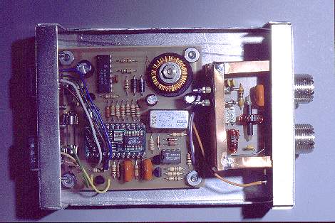
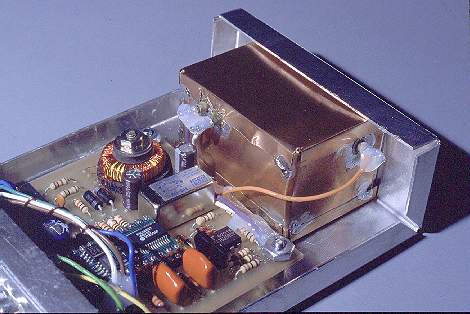
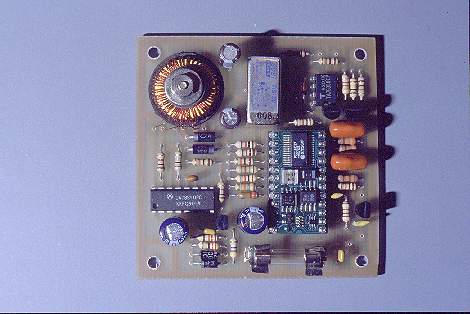 The controller
was assembled on two single-sided glass epoxy printed circuit boards. One
holds all the low frequency parts, while the other holds the SWR sensor
and is installed in a shielded enclosure. Here is the copper
pattern for both boards, and here is a simple component
placement diagram, which should help you to populate the boards, together
with the photos.
The controller
was assembled on two single-sided glass epoxy printed circuit boards. One
holds all the low frequency parts, while the other holds the SWR sensor
and is installed in a shielded enclosure. Here is the copper
pattern for both boards, and here is a simple component
placement diagram, which should help you to populate the boards, together
with the photos.
Note that C9 and C10 are relatively large. These capacitors need to
have reasonable temperature stability, so I used plastic caps.
The pin layout of the relay will not necessarily match that of the relay
you may find. In such a case, you will need to modify the board, or use
some wires to connect it.
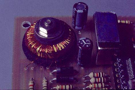 The toroid
for the DC-DC converter was mounted using a bolt, and foam rubber washers.
This is quite elegant, but you could as well use hot melt glue to hold
it onto the board!
The toroid
for the DC-DC converter was mounted using a bolt, and foam rubber washers.
This is quite elegant, but you could as well use hot melt glue to hold
it onto the board!
This transformer is wound with thin magnet wire, the exact diameter
being uncritical. I used a wire about 0.25mm thick.
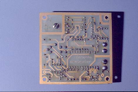 The solder side
of the board shows that this is easy to assemble. Nothing fancy here!
The solder side
of the board shows that this is easy to assemble. Nothing fancy here!
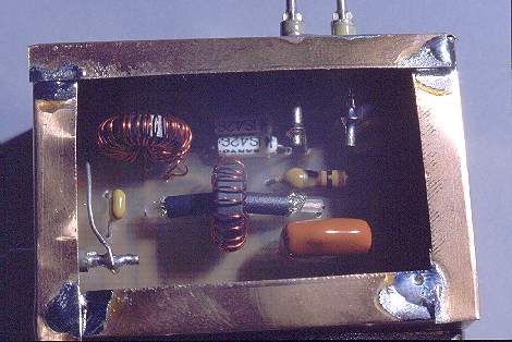 The SWR sensor
was enclosed in a shield made in cheap, quick and dirty fashion from some
0.1mm copper sheet. Feedthrough capacitors are used for the three DC leads
entering the shield. The value of these feedthrough caps is uncritical.
Mine were unmarked junkbox parts, probably around 1nF.
The SWR sensor
was enclosed in a shield made in cheap, quick and dirty fashion from some
0.1mm copper sheet. Feedthrough capacitors are used for the three DC leads
entering the shield. The value of these feedthrough caps is uncritical.
Mine were unmarked junkbox parts, probably around 1nF.
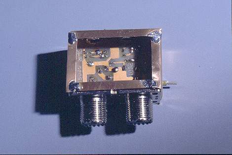 The coaxial connectors
were first bolted to the external case and the open shield. Then the PCB
was soldered to the center pins, followed by assembling and soldering the
shield. The entire sensor can be removed from the external case without
removing the connectors.
The coaxial connectors
were first bolted to the external case and the open shield. Then the PCB
was soldered to the center pins, followed by assembling and soldering the
shield. The entire sensor can be removed from the external case without
removing the connectors.
 The case was built
from two pieces of 1mm aluminum sheet. The SWR sensor is held in place
just by the coax connectors and the soldered shield, while the main board
is mounted with four screws and spacers.
The case was built
from two pieces of 1mm aluminum sheet. The SWR sensor is held in place
just by the coax connectors and the soldered shield, while the main board
is mounted with four screws and spacers.
 After testing
and before closing the controller, liberal amounts of hot melt glue were
used to immobilize anything that could otherwise shake and become loose.
After all, I'm using this controller in a 4WD vehicle which I drive over
all kinds of terrain, so some considerable mechanical stress is unavoidable.
And it's no fun to disassemble half of the car to dig out a failing controller,
only to find a broken wire or solder joint! Prevention is the best remedy.
After testing
and before closing the controller, liberal amounts of hot melt glue were
used to immobilize anything that could otherwise shake and become loose.
After all, I'm using this controller in a 4WD vehicle which I drive over
all kinds of terrain, so some considerable mechanical stress is unavoidable.
And it's no fun to disassemble half of the car to dig out a failing controller,
only to find a broken wire or solder joint! Prevention is the best remedy.
 The shield of
the SWR sensor is completed by top and bottom covers soldered in place
at only a few spots. These are easy to remove, should that ever become
necessary.
The shield of
the SWR sensor is completed by top and bottom covers soldered in place
at only a few spots. These are easy to remove, should that ever become
necessary.
I used this kind of extensive shielding in order to prevent any noise
from the Basic Stamp or the DC-DC converter oscillator getting into the
receiver. I did not try without the shield, but maybe such care is not
even necessary! Still, it's cheap insurance against noise problems.
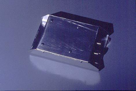 This is the completed
controller. One side carries the coax connectors, while the other has the
power/data connector and the programming connector. The cover of the box
is shaped such that it can be used to mount the controller to the car,
using sheet metal screws, with ample freedom of where to drill the holes
for them.
This is the completed
controller. One side carries the coax connectors, while the other has the
power/data connector and the programming connector. The cover of the box
is shaped such that it can be used to mount the controller to the car,
using sheet metal screws, with ample freedom of where to drill the holes
for them.
I did not apply any finish to the case. This was unnecessary, since
the location chosen for the controller is well protected from water, abrasion,
and completely out of view.
The software:
The nicest thing about the Basic Stamp, and which offsets its relatively
high cost, is the ease and speed of programming it. Here is the program
that has to be loaded into the Stamp. It can be read and modified by any
text editor, such as Windows' Notepad, but for loading it into the Basic
Stamp you need the proper software, which is available free of charge from
Parallax,
the manufacturer of the Stamp.
The flow diagram of the software is the following: After powering up,
the controller waits for the radio to prompt for any connected tuners,
and replies to it just like an AT-50 tuner would do. This will light the
"AT" indication on the radio's display, and allow further commanding the
controller. It will then wait for such further commands.
When a command arrives, the controller will acknowledge and then execute
it. The important commands are the "start tune" and the "bandset" ones.
There is also the "enable tuner" command, which is interpreted just
like the "start tune" one, and the "stop tuner" command, which is acknowledged
but otherwise quietly ignored, since the tuning portion in this antenna
cannot be switched off!
When a tune command is received, the controller first looks at the included
band information. If the radio is asking to tune on a band below 40 meters,
the controller answers with an error code, since these bands are not supported.
If the band is 40 meters or higher, then the controller checks whether
the SWR is totally sky-high, or if something close to a resonance can be
seen. If the antenna is close to resonance, the controller immediately
starts the fine tuning algorithm. Otherwise, the coarse tuning, or "search
mode" is started.
In search mode, the controller first tries to determine if the coil
tap must be moved up or down. If the antenna had already been tuned before,
without shutting off the radio in between, the previous band will have
been stored in memory, and the controller will compare this to the present
band, thus easily determining if it has to tune up or down. But if the
previous band is unknown, the controller will apply a best guess: If the
band is 40 meters, it will tune down, and if the band is any other, it
will tune up. This provides the shortest tuning time expectancy, since
the 40 meter resonance is achieved with the tap very close to the bottom,
while all other bands need the tap located somewhere in the upper half
of the coil.
The coarse tuning will run the servo at full speed, while continuously
measuring SWR, until it drops below a value of about 5:1. In fact, the
internal SWR measuring routine does not calculate the actual SWR, but simply
a relative resonance value: 10 means no resonance at all (infinite SWR),
and the higher values are better. Typical values for the fully tuned antenna
are between 20 and 50. The value at which the coarse tuning will end can
be preconfigured in the constants declaration section at the start of the
program.
If the controller had guessed the wrong direction of tuning, which would
happen for example when you had the antenna tuned on 12 meters, then switch
off, the next day switch on, change to 17 and then hit the AT TUNE button,
then the servo will drive the tap right to the end of the coil without
the controller finding a resonance. As soon as the limit switch stops the
servo, the controller will sense the current drop, and start the servo
in the opposite direction, quickly finding resonance. But if changing servo
direction does not make the current restart, the controller will assume
that there is a problem, and send an error message to the radio, which
will then emit its characteristic error beeping. This situation happens
when the antenna was not installed, or when it cannot be tuned, such as
if the car was parked with the antenna touching a wet tree!
When the resonance has been detected, fine tuning starts. This consists
in moving the servo in small steps by controlling the runtime, and measuring
the resonance level between steps. The controller tries to find and overshoot
the best possible value by stepping until the resonance starts going down,
then changes direction and repeats this. After this step, it is known on
which side of perfect resonance the tap is. The controller now moves the
servo in very small steps in the correct direction, until hitting precisely
the optimal setting. Then it sends a code back to the transceiver, telling
that the tuning procedure is complete.
If at any time during the tuning process the radio drops out of TX mode,
or otherwise the RF power becomes too low or too high for tuning,
the controller will stop the process and send an error code to the radio.
The time taken for fine tuning is just about 5 seconds, and the worst-case
resonance search still completes in well under one minute. Average band
changing time is 15 seconds. While this is slower than some autotuners,
it's still quite fast compared with some commercial antennas, and a huge
lot faster than getting out of the car, changing resonators and fine-tuning
a whip!
The software has enough comments to allow understanding it. When adapting
it to different radios, it may be necessary to change not only the commands
and answers, but maybe also the serial port parameters. If you will do
any modification to the program, I suggest you download the Basic Stamp
II manual from the Parallax site. The hardest part about adapting the controller
to another radio is finding out exactly what commands the radio sends,
and what answers it expects!
Installation in the car:
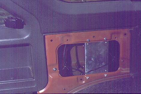 This is where the
controller was installed. My Nissan has lots of unused room between the
external skin and the internal plastic sheating. So I removed a plastic
cover close to the rear seat, and installed the controller there, using
four sheet metal screws. Then the plastic cover was reinstalled, completely
hiding the controller. All cables were routed under the plastic covers,
making a neat and clean installation. It should also be noted that both
antennas (HF and VHF) were installed at those two spots of the roof below
which the cabin lights are. This allows easy access by removing the lights,
and after reinstalling them the antenna installation is invisible from
the inside.
This is where the
controller was installed. My Nissan has lots of unused room between the
external skin and the internal plastic sheating. So I removed a plastic
cover close to the rear seat, and installed the controller there, using
four sheet metal screws. Then the plastic cover was reinstalled, completely
hiding the controller. All cables were routed under the plastic covers,
making a neat and clean installation. It should also be noted that both
antennas (HF and VHF) were installed at those two spots of the roof below
which the cabin lights are. This allows easy access by removing the lights,
and after reinstalling them the antenna installation is invisible from
the inside.
By the way, do you know how to drill a hole into the roof of a new car?
Here is the recipe: First mark the spot where you need to drill, and check
several times that it is correct. After drilling you cannot go back. Then
install a sheet metal drill bit of the proper size (12mm for this antenna)
in your electric drill. Place the drill against the roof. Firmly shut your
eyes. Collect all your courage, clench together your teeth, and press the
trigger. It will be over very quickly, so it won't hurt for long! Soon
the antenna will close the two wounds: The one in the car's roof, and the
other one in your heart!
Joking aside, I would like to stress that really the best way to install
a mobile antenna, specially an HF one, is through a hole in the car roof.
I have done this on all my cars, and never had any trouble from it. When
reselling a car, I simply close the hole with some properly sized cover
of discrete appearance, and even while I have pointed out the existence
of the hole to prospective buyers, I have never come across one who would
see the hole as a problem.
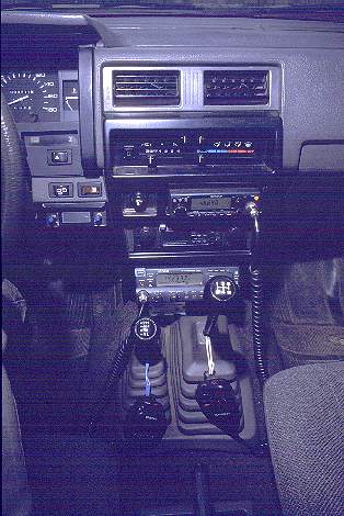 The
TS-50 was installed under the center console. For this to be possible,
I had to remove and discard a plastic cover (I stored it for the day I
resell the car), and I made new covers from vinyl-sheeted aluminum, to
close the areas not used by the radio. Two steel bars holding the console
had to be slightly bent outwards, and spacers had to be installed, to allow
the radio to be pushed in deep enough for a neat installation.
The
TS-50 was installed under the center console. For this to be possible,
I had to remove and discard a plastic cover (I stored it for the day I
resell the car), and I made new covers from vinyl-sheeted aluminum, to
close the areas not used by the radio. Two steel bars holding the console
had to be slightly bent outwards, and spacers had to be installed, to allow
the radio to be pushed in deep enough for a neat installation.
A ClearSpeech DSP filter was installed under the TS-50 using double
sided foam tape. While such a filter cannot make signals audible that are
deeply buried in noise, it really helps a great deal in making HF mobile
operation less tiring, by removing almost all noise. Without the filter,
when you drive under power lines there will be deafening noise. With the
filter, the only thing that happens is that the signal fades out while
you are under the lines, but no loud noise shows up. Comparing with earlier
filterless times, I found that the DSP filter caused me to do about three
times as much mobile operating as I would have done without it!
Speaking about noise, my car is quite RF-clean. It uses a carburetor,
has no electronic engine management systems, and the only electronics in
it are the voltage regulator, and a few simple circuits such as the rear
wiper controller. This helps a lot in obtaining low RF noise! The ignition
system is almost noise-free as it comes, so there was no need for improvement.
My main noise source when traveling are roadside powerlines, which unfortunately
are very common, and escape from my control!
The VHF transceiver, a TM-241, fits nicely into the hole left after
removing the ash tray. I'm a nonsmoking ham, and have a lot more use for
a radio than an ash tray!!!
I do not use the internal speakers of the radios. Instead, I use the
existing car speakers by wiring up a 4-pole relay in such a way that when
either of (or both) the TS-50 and the TM-241 are switched on, the relay
connects the left front speaker to the TM-241 and the right front speaker
to the TS-50 (via the DSP filter), while the two rear speakers remain connected
to the car radio. When both transceivers are off, all four speakers are
connected to the car radio, for good music reproduction.
The power for the two transceivers is brought through the firewall by
a pair of heavy wires, connected to the battery and properly fused there.
These wires split to carry the power connectors for both radios and some
additional outlets for a GPS receiver, altimeter, notebook computer and
diverse other playthings.
The two microphones are hooked to two wires shaped into mike holders
and engaged to the gear lever and the transfer lever. They are always within
easy reach. The mike of the TS-50 has four programmable buttons. I programmed
two of them to step the bands up and down, and another for activating the
AT TUNE function. The modus operandi is simple: I take the mike, switch
to the desired band, use the up/down buttons to tune to a clear frequency
close to the one I need, and press the "AT TUNE" button. My antenna will
tune to the exact frequency, and when it has arrived there, the radio beeps
shortly and drops back into RX. Then I go to the exact frequency, and make
the contact. As simple as that! And on all bands from 40 to 10 meters!
Performance
Some of you may ask why I didn't include coverage of 80 and 160 meters
in this design. The reason is one of performance. In any antenna, the radiation
efficiency is given by the ratio between the radiation resistance and the
total loss resistance. In physically short antennas the radiation resistance
is low, and becomes very low when the antenna is really short.
Loss resistance, on the other hand, is given mostly by ground loss and
the equivalent series resistance of the loading coil. Let's see what happens
on different bands:
On 10 meters, this antenna has a radiation resistance of about 20 Ohm.
The coil resistance is negligible, and ground loss is probably less than
3 Ohm, because most ground current is captured by the car, which is large
enough on this wavelength to effectively shield the antenna from the ground.
Thus, the efficiency on 10 meters will be around 85%, which will be indistinguishable
from a "perfect" antenna.
If we double the wavelength to 20 meters, the radiation resistance drops
to around 5 Ohm. The loading coil will need to be tuned to a reactance
of roughly 500 Ohm. Given a Q factor of 250 (not higher, because part of
the coil is shorted!), this would cause about 2 Ohm of coil loss. The ground
resistance may be around 5 Ohm, placing the total efficiency of the antenna
at somewhat above 40%. This is about 4dB down from a perfect antenna. The
loss can be noticed, but not too much.
On 40 meters the situation changes a lot: The radiation resistance is
down to only 1 Ohm! The loading coil needs to provide a reactance of roughly
1400 Ohm. The Q is better here, because almost no turns are shorted, approaching
350. Thus we get a coil loss of 4 Ohm. The ground loss is higher
on this band, because so much more ground current returns via the soil.
It will probably be around 6 to 8 Ohm, depending on terrain. The result
is that the efficiency of the antenna on 40 meters is less than 10%! This
represents a loss of 10dB compared to a perfect antenna. Such a loss is
easily noticeable, and you will get lower reports than from the home station,
but definitely a lot of contacts can still be done.
But on 80 meters the situation turns dramatic: A whip this size would
have a radiation resistance of only 0.2 Ohm! Coil loss would be around
10 Ohm, even for a very large coil, and ground loss should be expected
at about 15 Ohm. The resulting less than 1% antenna efficiency represents
a loss of more than 20dB. On the generally noisy 80 meter band, this is
such a severe handicap that I decided to stay out altogether.
On 160 meters of course the situation is much worse: Radiation resistance
would be only about 0.07 Ohm, coil loss at least 20 Ohm, ground loss no
less than 30 Ohm, and the total antenna "gain" would be close to -30dB!
I doubt if any useful work could be done down there. Operating the very
low bands from a car requires different approaches, either using oversize
whips with top loading, or using loops made from very large copper tubing.
Both are mechanically cumbersome.
Comparing this antenna side by side to several commercial ones, installed
on other ham's cars, the performance turned out to be equal to the best
antennas of comparable length, and surpassing many of the cheaper models
available. But at the same time this antenna is lighter, and easier to
dismount and store, than any comparable commercial antenna I saw! The convenience
of automatic tuning to any frequency is matched only by a few commercial
antennas. The tuning speed was surpassed by one, but that antenna used
a fairly large tuner box, and was expensive.
Many commercial antennas were very heavy, and being bumper-mounted,
had problems of detuning while swaying. My antenna is essentially free
of of detuning, even if the thin whip sways widely! The reason is simply
the roof-mounting: The whip can sway a lot without getting significantly
closer to the car or the ground.
You will have noticed that no spring is used to mount this antenna.
In fact, the driver needs to be careful not to hit any hard object with
the loading coil, as this would cause damage. But the highly flexible whip
is very resistant to impact! I have caressed trees at highway speeds, and
a few times I forgot to take off the antenna before driving into a garage.
In all cases the whip flexed out of harm's way.
During a long trip to remote places in southern Chile during december
2001 and january 2002 I thoroughly tested this antenna. It got heavy rain,
high speed driving, lots of abuse on overgrown forest tracks, while providing
many contacts on all bands. The excellent results obtained prompted me
to make the design available to the ham community.
The End
Previous page
Back to Homo Ludens Electronicus.
 The circuit inside the shield is the SWR sensor. T1 is a current mode transformer.
On its secondary side there is a sample of the current present on the coax
line, which is 1/22 of the line current. This current is applied to R1,
so that a voltage appears on it, which has a magnitude of 4.545 Volt for
each Ampere on the line.
The circuit inside the shield is the SWR sensor. T1 is a current mode transformer.
On its secondary side there is a sample of the current present on the coax
line, which is 1/22 of the line current. This current is applied to R1,
so that a voltage appears on it, which has a magnitude of 4.545 Volt for
each Ampere on the line.