Voltage regulator for synchronous
generator
Most present-day synchronous generators come with a built-in voltage
regulator, fancily called automatic
voltage regulator,
or AVR. But that wasn't true many years ago. Very old machines from the
day before cheap electronics typically had an excitation scheme that
used a rheostat-adjusted voltage excitation, in addition to a
load-dependent component derived from a current transformer that sensed the load current. The user
had to crank the rheostat up and down as needed.
Years ago I built a small secondary microhydro system, using a plastic turbine,
and I got an old generator for free from a friend, to couple to my
turbine. This old generator came from an Honda E1000E gasoline-powered
genset, apparently made around 1970, whose engine had worn out beyond
reasonable repair. I got the bare generator, without any of the
external circuitry. So I had to make an AVR for it.
This generator has a main winding for 220 V, 1000 W, without any taps,
in addition to a tapped low voltage winding good for charging 6 V or
12 V batteries at several amperes, and it also has a 2×55 V
center-tapped winding, intended to provide excitation power. The field
winding, connected through slip rings and carbon brushes, has a
resistance of 15 Ω, and an inductance of very nearly 10 H.
The combination of a low resistance field winding with that relatively
high voltage excitation winding proved to be a problem. My first AVR for this
generator rectified and filtered the 55 V, obtaining roughly 70 VDC,
and applied this to the field winding through a typical AVR circuit,
using a bipolar Darlington power transistor in a self-oscillating zener-regulated
circuit. It sort of worked, but had a stupid problem: When the
generator was spinning too slow to achieve nominal output, the
regulator would apply full drive to the field coil, which at 70 V is
327 W, and that's rather hefty for a 1000 W generator! And it's totally
useless, because at about 20 V applied to the field, the generator's
iron totally saturates, and any further excitation doesn't increase the
output! But the 327 W excitation, plus losses in the totally
oversaturated iron, put such a hefty load on the turbine, that when the water supply was scarce it
failed to get up to the nominal running speed.
I tried powering the AVR from the 12 V winding instead, but that proved
to be too little. It maintained regulation only up to about 500 W load, and
beyond that the voltage would sag.
I tried adding the 12 VAC to 5 VAC obtained from an external
transformer, but it added only 1 V! This is because this generator,
like many, has the auxiliary windings installed 90 degrees out of phase
to the main winding, and so my 5 V transformer, powered from the
220 V output, was at 90 degrees with the 12 V winding.
The solution was to use the 12 V winding in combination with a voltage
doubler. That provides enough excitation even for full load, and at the
same time limits the excitation at undervoltage conditions to a
reasonable value, about 60 W. The cost is larger filter capacitors.
But I wonder why Honda put a 55 V excitation winding on that machine,
combined with such a low voltage field winding!
Another problem was lack of self-starting. Modern generators almost
always are made from materials that hold enough remanent magnetism to
allow the generator to self-excite when starting up.
Some
even include a small permanent magnet to assure quick self-starting. But not
this one!!! It has no magnet, and almost no remanence. When spinning it
up to full speed, the main winding generates less than one volt on
remanence, and the auxiliary winding can't overcome a diode drop!
Honda solved that problem nicely by providing external excitation to
the generator, taken from the engine's magneto. But my hydro turbine
doesn't have a magneto... So I had to add a small rechargeable battery
to my AVR, to provide start-up excitation! That works fine, but it
looks a bit odd to have batteries inside a generator!
And the third problem was an encounter with a counterfeit transistor. I
used a TIP142 in my first-generation AVR, and it died a very early
death. That was very
strange, because that transistor is enormous compared to the current,
voltage and power it had to master in this circuit! There is no chance
for the operation point to come anywhere close to the safe operation
area limits for that transistor.
Since I had bought several of those, very cheaply, in a local
electronic parts store, I took another, mounted it on a hefty heat
sink, and applied some controlled voltage and current to it. When I
made it conduct just slightly over 2 A, in saturation, with less than
3W dissipation, it shorted out! Definitely this was not
a
genuine TIP142. I don't know who faked them, and what type
they really are, but
certainly they are not usable in place of a real TIP142! The values of
the internal resistors also measured totally different from what the
TIP142 datasheet says.
Let this be a warning to my dear readers. Get your parts from reliable,
trustworthy distributors, not from any unknown eBay vendor,
and
not even from a small local parts store. The world has been swamped
with counterfeit parts, that simply don't perform anywhere close to the
datasheet specs. I have essentially stopped buying parts in local stores, for this reason.
Not having any other bipolar Darlington power transistor at hand, I
used a MOSFET instead, of which I had many. And that's how the final
AVR circuit for this Honda generator came to be.
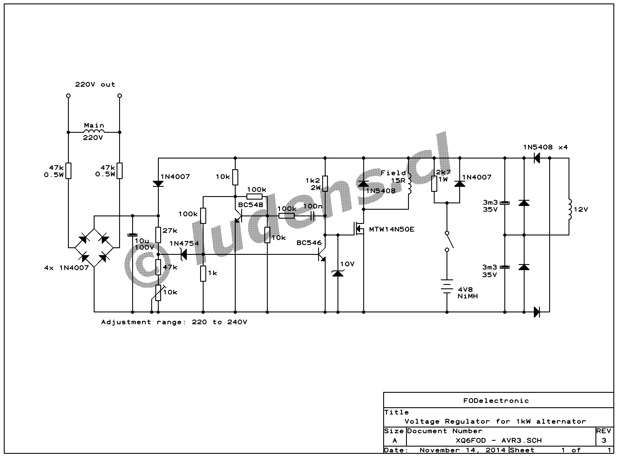
And now, finally,
you get to see
the schematic! And if you want to see it larger, or print it, just
click on it to get the big version.
If you have seen other AVR schematics, you will notice that this one is
quite similar in its fundamental operation. But there are some
differences to the most typical designs. For example, I placed the
10µF capacitor, which filters the voltage sample, behind a large portion
of the total resistance in the divider, unlike most designs that place
it pretty much at the input, without the 47k resistors in front of the
bridge rectifier. My approach is neither better nor worse than the
standard one. It's simply different. The standard design will tend to
regulate the peak voltage, while mine will tend to regulate the average
voltage. The former is best for powering electronic equipment, while the latter is best for avoiding light flickering.
The 12 V winding feeds a voltage doubler, that's made with 4 diodes,
rather than the more usual 2-diode design. The additional diodes
basically provide protection against reverse polarity on the filter
caps, in the event of any weird phenomenom occuring in the generator's
stator, caused by loads with poor power factors. Most likely these
extra diodes aren't really required, but they are cheap protection. And if
you want me to be honest to the bones, I have to confess that mainly I
have them in the circuit because I was too lazy to remove them, when I
changed the rectifier configuration from a bridge to a voltage doubler!
The 1N4007 feeding supply voltage into the 10µF capacitor is another
useless remnant. In my original AVR, powered by the 55V winding, this
diode would become forward biased when the generator is
loaded by
a very crooked load (low power factor), that drives up the 55V and down
the 220V. This diode would then make the AVR regulate the
55 V
winding rather than the depressed main one, providing protection against burning
out the AVR from excessive supply voltage. Now, with the
AVR powered from about 25V, there is no risk of this, and at the same
time this diode will never be forward biased, and is thus exemplarily
useless! I didn't remove it because of sheer laziness (did I mention
already that I have been becoming lazy lately?), but you might want to
use this idea if you will adapt this AVR to some generator that does
need a higher excitation supply voltage than mine.
The most special part in this AVR is the battery pack, which consists
of four AA-size NiMH cells. It's provided with a switch, so the
battery can be disconnected when the generator is not in use. When the
switch is on, the battery powers the circuit through the diode,
providing enough voltage to turn the MOSFET on, and puts enough current
through the field winding to make the generator start up at once, when
it begins rotating. During normal operation, the battery is
trickle-charged through the 2k7 resistor. If you are making an AVR for
a generator that has enough remanence to self-excite, then of course
you don't need to include the battery circuit! But with such a
generator you might want either a bipolar transistor, or a MOSFET or
IGBT with a very low threshold voltage, instead of the standard MOSFET
I used. Because that generator might generate enough voltage on
remanence to overcome the rectifier diodes' drop, but not enough to
bias a normal MOSFET into conduction!
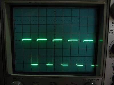 The
two small transistors and the power MOSFET constitute a pulse width
modulation cell, that modulates cleanly all the way from zero to 100% duty cycle.
The scope screenshot shows the waveform at the MOSFET. The
frequency is low, around 100 Hz, leading to high switching efficiency
despite the large gate resistor. A higher frequency isn't needed,
because of the very high inductance of the field winding, which holds
the field current highly constant while the field voltage switches
between zero and about 25V at 100Hz.
The
two small transistors and the power MOSFET constitute a pulse width
modulation cell, that modulates cleanly all the way from zero to 100% duty cycle.
The scope screenshot shows the waveform at the MOSFET. The
frequency is low, around 100 Hz, leading to high switching efficiency
despite the large gate resistor. A higher frequency isn't needed,
because of the very high inductance of the field winding, which holds
the field current highly constant while the field voltage switches
between zero and about 25V at 100Hz.
The control loop response is that of a simple proportional function
with a narrow action range (high gain). It holds the
voltage
"stable as a plank" during speed and load variations, at least when
looking at it on my analog panel voltmeter! Actually the output voltage
fluctuates by about 1% when the load changes from zero tu full, but
that's pretty acceptable. The good thing is that such a simple, slow,
proportional controller is unconditionally stable.
The component values were chosen so that with the trimpot at the center
of its range, the output voltage is regulated to 230 V, with the
components I got. The range of the trimpot should be enough to
compensate for the normal tolerance of the parts. The zener diode is
used at pretty low current, though, so it might happen that
you
get one that has a significantly different zener voltage than mine, at
that current. In that case feel free to change the value of the 47k
resistor in series with the pot, as needed to get the proper output voltage
while the pot is in a reasonable position.
The MOSFET I used is brutally oversized for the task. I used it because
I was given a large bag full of them. Feel free to use a different one.
There isn't much more to say, really. It's a simple circuit.

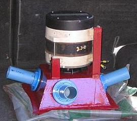
I built this AVR in the "printed-circuit-boards-are-for-sissies" style.
Anyway it would have been hard to make a board that fits
under the
back cover of this generator with the big parts on it - and instead my
antique-radio-reminiscent construction fits very well!
I bolted the MOSFET to a convenient hole in the generator's housing,
which is made from thick cast aluminium, and makes a marvelous
heatsink. Normally a heatsink isn't even necessary in this circuit, but
if the oscillation should stop for any reason, and the MOSFET goes into linear mode,
the heatsink will save its life.
Then I mounted the switch on a simple bracket, tied down the battery
pack and some other large parts with double-sided foam tape "for heavy
object mounting" and cable ties, bolted three terminal strips to
additional threaded holes in the casting (thanks, Honda, for all those
convenient holes!), and soldered the other parts and the wires to them.
Ready. It works perfectly, and after closing the cover it even starts to look
good!
 With
a generator driven from a combustion engine, this construction
style might not be entirely optimal, as some long-legged parts might
enter resonance and end up fatiguing and breaking their legs. But I'm
running the generator from
a water turbine, which is basically vibration-free, so it has worked
fine for several years. Once a year I check the brushes, and clean the
carbon dust from the circuit, using a paintbrush and a vacuum cleaner.
With
a generator driven from a combustion engine, this construction
style might not be entirely optimal, as some long-legged parts might
enter resonance and end up fatiguing and breaking their legs. But I'm
running the generator from
a water turbine, which is basically vibration-free, so it has worked
fine for several years. Once a year I check the brushes, and clean the
carbon dust from the circuit, using a paintbrush and a vacuum cleaner.
Okay. If you need an AVR, you might go into all the trouble to build
your own, adapting my circuit to the needs of your generator, or using
another standard design, or designing your own from scratch. I hope my
circuit gives you some useful ideas in that case. Or you can go to eBay
and buy a ready-made Chinese AVR for surprisingly little money. They
are available in many models, for many generators, and most of them do indeed work -
at least for some time. The problem with many of them is that they are
built to the absolute minimum expression, they have no heatsink, have
very tiny electrolytic caps, and so on. For a generator used a few
times per year during power outages or camping trips, they might be all
you need, but for a generator that will run 24/7 for many years, you
need something designed with a bit more headroom, specially to make the
electrolytic capacitors last. For such applications, a homemade AVR is a good idea.
It's also educational and fun to build your own.
Back to homo ludens electronicus.